Let me know if you need anything. By the end of this, I will have a near complete clutch assembly that I would be willing to part with for a fair price.
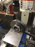
Mine was noisy as well. I tried to find an off the shelf replacement, but I was unable to track one down for a reasonable price. I disassembled the bearing, cleaned and re-greased. It’s not perfect, but it seems to be doing okay so far. If I had problems with it, I was planning to try out a sleeve bearing in its place made from nylatron or oilite. I should have asked clausing if a replacement was available when I had them on the phone.
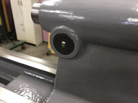
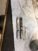
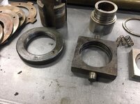
On my machine it helped greatly to align the clutch assembly using the u bolt and set screw shown. When it was out of alignment I was getting odd feedback, high engagement pressures and noises. Took me a few tries and a bit of trial and error, but it worked out in the end. Initially I left the adjustment where it was when I received the machine, but it was way off.

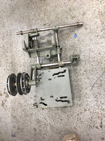
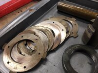
It also helped greatly to file smooth and polish these faces. You can’t remove too much material and you want the geometry on both fingers to stay pretty close to the same, but it allowed the clutch to fall into place instead of catching and binding like it was before.

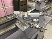
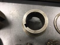
I think I understand this correctly. By over center I assume you are talking about the position of the clutch lever. This can be changed by using this arm. There is a pinch bolt that will allow you to move the clutch arm to where you want it, and lock it in place. I will also note that when the fingers are fully engaged into the slots in the clutch slide, the tension on them is allowed to repeat. That way it’s not left up to the operator on how hard he or she decides to lean on the lever. It has a positive location where the tension stays the same once in position. I hope that makes sense. Hard for me to explain.

The best advice I can offer is to keep it oiled and clean. Before I had heat, every time I got a few minutes, I would wipe the machine down with a coat of oil. This did well, but it wasn’t perfect. A little flash rust may get through here and there, but as long as I caught it fast, it wasn’t much of a problem. I know you don’t want to, but on handwheels, dials, and non precision surfaces I would use rust oleum crystal clear enamel in a rattle can after a quick wire wheel or polish. This works very well and keeps them looking new. I’ve also used 2 parts boiled linseed oil mixed mixed with 1 part mineral spirits to coat non precision surfaces. It takes a while to dry, but it is easy to apply and re-apply with a rag.
Sent from my iPhone using Tapatalk