To avoid these ads, REGISTER NOW!

Convert 3.5" round workbox to outlet

aragno

Active member
Joined
Oct 31, 2021
Messages
28
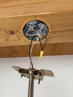
I have a porcelain light bulb holder in my garage ceiling.
I wish to plug in 2 LED lights (65 watts each).
This light is on a single switch.
I want to plug in the 2 x LED lights I have and I'm happy to install an outlet for the sole purpose of these 2 lights.

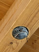
I have taken this photo inside the workbox but unsure how to tackle this one.
As the box is shallow, I feel I should remove the workbox and install a new one that is deeper.
What workbox should I use?
What outlet and adapter plates/covers?
Any specific outlet I should select?
I am unsure of what to do with the 3 sets of wires + ground.
1 x red
2 x white (together on the light)
2 x black (capped together)
2 x ground

I'd like to the option to install the porcelain light when/if we move.
IMG_0750.jpeg

Once I have this wired in, can I install a GFCI switch like this next to the existing wall switch?
1788197884106.png
If so, i'll separately post about how to correctly wire this next to the switch.
 
To avoid these ads, REGISTER NOW!

dscheidt

Well-known member
Joined
Apr 26, 2017
Messages
2,964
You can get a listed receptacle and plate combination for a 4" box. (There are also covers available without the receptacle, but they're not code compliant, because code requires at least two screws. The listed assemblies use a rivet.) Either replace the box with a proper one, or get a round back 1900 extension box, depending on your tolerance for things looking like they're done by a hack, and put your receptacle in that.

You can use a dead front gfci like you show, but you'd have to make sure the neutral is in the switch box.
 

rust in the eye

Well-known member
Joined
Oct 2, 2017
Messages
2,903
Location
Chicagoland
Why a GFCI for a ceiling mounted fixture?
A lamp holder with a receptacle show in post #2 seems a fine choice from here. Good ones will come from an electrical supply house, the ones at big orange etc. are garbage. I'd imagine the ones you can't lay a hand on until you own them from the jungle to be as bad or worse.
 
OP
A

aragno

Active member
Joined
Oct 31, 2021
Messages
28
I managed to install this in similar fashion as the light was wired (2 white on one side, red on another, and connected the ground wires (previously not in use with the light bulb holder).
The switch is working and the outlets are now working.
my round box was a 4" and I was able to accommodate this. I will add a 1/2" space ring to give a little more space, but for now, it's functional.


1788278353489.png
This circuit/breaker provides power to this former garage ceiling light, and 2 ceiling lights in nearby rooms.
This garage light was operated by a switch on the wall. Next I would like to install a GFCI near the switch in the garage since code requires a GFCI to be on the outlet circuits in a garage, regardless of location/position.
 

dscheidt

Well-known member
Joined
Apr 26, 2017
Messages
2,964
I may be missing something here but it seems like the key piece that's needed is a 3-1/2 inch round fixture cover punched for a duplex receptacle.
They don't exist. a 3.5 box isn't big enough, a 4" is. As I noted earlier, most of the outlet covers available are not code compliant, as code now requires the receptacle to be held by two screws. There are listed assemblies of a cover and an outlet.
 
OP
A

aragno

Active member
Joined
Oct 31, 2021
Messages
28
Because NEC 210.8(A)(2) says that all receptacles in a garage are to be GFCI protected. There is no exception for ceilings.
Can I install a blank-face GFCI next to the switch that controls that former light, which is now a switched outlet?
 

Shiftless

Well-known member
Joined
Mar 9, 2014
Messages
14,882
Location
East Bay SFO
Would it be kosher to use the existing screw holes to screw on a 4 inch square box? After that was up there, you could pull a Black, White, and Ground wire out through the middle punch out hole of the 4 inch box and from there wire in one or even two duplex receptacles.
Wire in a dead front GFCI in your switch box or even a GFCI duplex receptacle in that box. Then you’ll be good to go.
 
OP
A

aragno

Active member
Joined
Oct 31, 2021
Messages
28
Would it be kosher to use the existing screw holes to screw on a 4 inch square box? After that was up there, you could pull a Black, White, and Ground wire out through the middle punch out hole of the 4 inch box and from there wire in one or even two duplex receptacles.
Wire in a dead front GFCI in your switch box or even a GFCI duplex receptacle in that box. Then you’ll be good to go.
I think the GFCI test and reset have to be accessible from the floor and no equipment requires to access it. That’s why I was thinking to install it next to the switch.

Based on the comment from @dscheidt it seems I need to open the switch and see if a neutral is present. I’m unsure what I’m looking for but I will snap a photo and see what I can learn.
 

sparky 1971

Well-known member
Joined
Oct 9, 2018
Messages
8,136
Location
Central Iowa
Can I install a blank-face GFCI next to the switch that controls that former light, which is now a switched outlet?
Yes, it's already been stated that a neutral is required. Cut it out to a two gang box, if it's already a two gand, make it a three gang and so forth.
I think the GFCI test and reset have to be accessible from the floor and no equipment requires to access it. That’s why I was thinking to install it next to the switch.
Correct.
Based on the comment from @dscheidt it seems I need to open the switch and see if a neutral is present. I’m unsure what I’m looking for but I will snap a photo and see what I can learn.
you are looking for two or more white wires connected together and not to anything else in the box.
 

cybrdyke

Well-known member
Joined
Sep 9, 2014
Messages
3,470
Location
USA
I may be missing something here but it seems like the key piece that's needed is a 3-1/2 inch round fixture cover punched for a duplex receptacle.
I dont believe a receptacle will mount into that box so there might not be a cover either. Correct me if I'm wrong, but I recently tried to find one and failed.
CD
 
To avoid these ads, REGISTER NOW!
OP
A

aragno

Active member
Joined
Oct 31, 2021
Messages
28
Yes, it's already been stated that a neutral is required. Cut it out to a two gang box, if it's already a two gand, make it a three gang and so forth.

Correct.

you are looking for two or more white wires connected together and not to anything else in the box.
I've removed the cover and it is a two (2) gang box with a second switch operating an outdoor light.
The switch on the left (red and black wires) is the switch controlling this new outlet. This is what I want to protect with a dead-face GFCI.
Inside I find 3 white wires all connected together with a wire nut. Is this what I am looking for and which ones of the three (3) do we need to use? The box is a cramped mess but I can look in and figure out which white wire is in the same bundle/romex, etc.
Let me know and I'll get on with it and post an update.

IMG_0771.jpeg

IMG_0774.jpeg

This is the wiring I found in the ceiling. The ground is now connected to the outlet I installed. I attached the red to the "brass" and the white to the silver screws on the other side of the outlet (one wire per screw) and left the "jumper plate/tab" in place.
IMG_0750.jpeg

I may have missed it, but just put a gfci breaker on the garage light circuit.
That's where I'm headed but I need to figure out which wires and if I have everything I need to make this work like it should.
 
Last edited:

dave*99

Well-known member
Joined
May 5, 2009
Messages
4,380
Location
Coastal NJ
This will be easier to diagram if we know whether the power from the circuit breaker enters the box with 2 switches (and continues to the ceiling light) OR does the power enter the ceiling light from the circuit breaker first and then continue to the switch box.

It appears BOTH the ceiling light and switch boxes are in the middle of things. Unswitched power continues on to another device somewhere. Making this work right will require the load side of the new GFCI be connected to all loads downstream of the GFCI. Point being the neutral on the load side can only be connected to loads supplied by the load side of the GFCI.

Thinking like this:

Breaker---------Switches------------ceiling light----------another unswitched load

OR

Breaker------ceiling light----------Switches------------another unswitched load

It's common to conserve wire, so I'll ask: Which is closer to the breaker? The ceiling light or switch? It's a possible clue. A test light and some troubleshooting is the best way to know.
 
OP
A

aragno

Active member
Joined
Oct 31, 2021
Messages
28
This will be easier to diagram if we know whether the power from the circuit breaker enters the box with 2 switches (and continues to the ceiling light) OR does the power enter the ceiling light from the circuit breaker first and then continue to the switch box.

It appears BOTH the ceiling light and switch boxes are in the middle of things. Unswitched power continues on to another device somewhere. Making this work right will require the load side of the new GFCI be connected to all loads downstream of the GFCI. Point being the neutral on the load side can only be connected to loads supplied by the load side of the GFCI.

Thinking like this:

Breaker---------Switches------------ceiling light----------another unswitched load

OR

Breaker------ceiling light----------Switches------------another unswitched load

It's common to conserve wire, so I'll ask: Which is closer to the breaker? The ceiling light or switch? It's a possible clue. A test light and some troubleshooting is the best way to know.
They are both fairly far away from the breaker box and the outlet in the ceiling is fairly close to the wall switch. The breaker box is on the other side of the house.

That breaker for the garage ceiling light/outlet also serves as the breaker for the utility room light and a dining room light.

How should I go about testing things? I have a Fluke multimeter if I’m told what to touch to test.
 

dave*99

Well-known member
Joined
May 5, 2009
Messages
4,380
Location
Coastal NJ
Start by turning both light switches and the breaker off. Go to the ceiling fixture and disconnect the 2 black wires under the wire nut.
Turn breaker on.

Lets call black #1 the black wire that resides in the same jacket as the red wire.
Black #2 is in the other cable with only white and ground.

Measure AC volts between black #1 and neutral.
And then black #2 and neutral.

Tell us the result.
 
OP
A

aragno

Active member
Joined
Oct 31, 2021
Messages
28
Start by turning both light switches and the breaker off. Go to the ceiling fixture and disconnect the 2 black wires under the wire nut.
Turn breaker on.

Lets call black #1 the black wire that resides in the same jacket as the red wire.
Black #2 is in the other cable with only white and ground.

Measure AC volts between black #1 and neutral.
And then black #2 and neutral.

Tell us the result.
While doing this, do you want me to test anything at the switch, or not yet?
After the kids go to bed, I'll head out to the garage to report back.
I made this quick PDF of the wiring.

Reference to "Jacket 1" in each diagram should not imply they are connected together, since we don't yet know that.
 

Attachments

  • Electrical Box Wiring Diagrams.pdf
    583.1 KB · Views: 9

dave*99

Well-known member
Joined
May 5, 2009
Messages
4,380
Location
Coastal NJ
While doing this, do you want me to test anything at the switch, or not yet?
After the kids go to bed, I'll head out to the garage to report back.
I made this quick PDF of the wiring.

Reference to "Jacket 1" in each diagram should not imply they are connected together, since we don't yet know that.
I’m hopeful the measurements I described gets us to understand which end the power enters from.

Your diagram would then expand to show whatever is downstream of these 2 boxes.

While you have the 2 blacks disconnected on the ceiling box and the breaker is on, see what else is dead. Other lights or receptacles in the area etc.
 
OP
A

aragno

Active member
Joined
Oct 31, 2021
Messages
28
Start by turning both light switches and the breaker off. Go to the ceiling fixture and disconnect the 2 black wires under the wire nut.
Turn breaker on.

Lets call black #1 the black wire that resides in the same jacket as the red wire.
Black #2 is in the other cable with only white and ground.

Measure AC volts between black #1 and neutral.
And then black #2 and neutral.

Tell us the result.
Okay... finally got to this!

in the ceiling junction box (where the outlet is installed)
Black #1 with red wire to white/neutral = 120v
Black #2 without red wire to white/neutral = 0v
** voltage is the same when the wall switch is "off" or "on"

While the black wires are disconnected from each other in the ceiling junction box, the outdoor light does not work and is on the same breaker as the garage ceiling and 2 other rooms. Those other 2 rooms are working as normal with the black wires separated.
 

dave*99

Well-known member
Joined
May 5, 2009
Messages
4,380
Location
Coastal NJ
Sounds like the breaker feeds the ceiling light first. Power enters on black 2 and leaves on black 1. Black 1 feeds both switches and the switches feed outdoor light and ceiling light.

I’m thinking you would need another neutral from switch box to ceiling light to make a GFCI work at the location of the switch box.

A GFCI breaker may be the only option.

@mm08822 or @wyliesdiesels may be able to confirm this or have another suggestion.
 

mm08822

Well-known member
Joined
Jan 13, 2012
Messages
6,284
Location
NJ
Power could be coming into the ceiling box from either cable. Unsplice both blacks in the ceiling outlet. Leave neutrals spliced. Which cable brings constant 120 into the box? (measure from black to neutral on both cables) It could be from either one. (red is usually switched, but it doesn't have to be) The 3 wire cable connects to the switch box. Switched power is probably on the red. Check it by flipping the switch to each position and measure red - neutral.

Answer these q's first so we don't have to discuss write a bunch of needless scenarios.
 

dave*99

Well-known member
Joined
May 5, 2009
Messages
4,380
Location
Coastal NJ
Power could be coming into the ceiling box from either cable. Unsplice both blacks in the ceiling outlet. Leave neutrals spliced. Which cable brings constant 120 into the box? (measure from black to neutral on both cables) It could be from either one. (red is usually switched, but it doesn't have to be) The 3 wire cable connects to the switch box. Switched power is probably on the red. Check it by flipping the switch to each position and measure red - neutral.

Answer these q's first so we don't have to discuss write a bunch of needless scenarios.
Start at post 21. These steps have been completed. Me thinks.
 

mm08822

Well-known member
Joined
Jan 13, 2012
Messages
6,284
Location
NJ
Start at post 21. These steps have been completed. Me thinks.
Ok, didn't see that as I was only responding to where your ping led me to. Ok, so post 21 is pretty close to what I suggested in post 28.

Always good to have a roadmap.

So it looks like power comes into the 2g box on jacket #2 or #3.
I don't think jacket #2 in the switch box is the same as the dwg indicates as jacket #2 in the ceiling outlet. Lets rename jacket #2 in the ceiling outlet as jacket #4. Jacket #4 goes to the floodlight.
Jacket #1 brings 2 switched legs into the ceiling outlet box along with a neutral.

Either jacket #2 or #3 provides power into the 2g box. Whichever one isn't the cable from the panel is bringing 120v out of the 2g box to other stuff. It's just daisy-chained in the 2g box.

If you want to gfci protect the ceiling recept (and floodlight) from the 2g location with a gfci dead front or gfci recept, you have to install it upstream of wirenut #2. Both switch's power has to come from the load side of the gfci. The neutral for jacket #1 has to go onto the load side of the gfci.

Either bust out the 2g box and put in a 3g or change the 2 single pole switches to a tandem switch device to make room the gfci device.

Or just change the cb to gfci version and cover the entire circuit without changing anything in the 2g box..
 

dave*99

Well-known member
Joined
May 5, 2009
Messages
4,380
Location
Coastal NJ
Ok, didn't see that as I was only responding to where your ping led me to. Ok, so post 21 is pretty close to what I suggested in post 28.

Always good to have a roadmap.

So it looks like power comes into the 2g box on jacket #2 or #3.
I don't think jacket #2 in the switch box is the same as the dwg indicates as jacket #2 in the ceiling outlet. Lets rename jacket #2 in the ceiling outlet as jacket #4. Jacket #4 goes to the floodlight.
Jacket #1 brings 2 switched legs into the ceiling outlet box along with a neutral.

Either jacket #2 or #3 provides power into the 2g box. Whichever one isn't the cable from the panel is bringing 120v out of the 2g box to other stuff. It's just daisy-chained in the 2g box.

If you want to gfci protect the ceiling recept (and floodlight) from the 2g location with a gfci dead front or gfci recept, you have to install it upstream of wirenut #2. Both switch's power has to come from the load side of the gfci. The neutral for jacket #1 has to go onto the load side of the gfci.

Either bust out the 2g box and put in a 3g or change the 2 single pole switches to a tandem switch device to make room the gfci device.

Or just change the cb to gfci version and cover the entire circuit without changing anything in the 2g box..
His tests lead me to believe the ceiling box is fed from the breaker. He needs a line and load neutral if he puts a GFCI in the 2g location. He has one neutral between the ceiling box and 2g switch box.
Yes? No?

When he opened up the ceiling wire nut the only black with 120 was the 14/2. Not the 14/3.
 

mm08822

Well-known member
Joined
Jan 13, 2012
Messages
6,284
Location
NJ
His tests lead me to believe the ceiling box is fed from the breaker. He needs a line and load neutral if he puts a GFCI in the 2g location. He has one neutral between the ceiling box and 2g switch box.
Yes? No?

When he opened up the ceiling wire nut the only black with 120 was the 14/2. Not the 14/3.
If that's the case, then the sketch is incomplete or wrong in other ways. Needs another cable in the ceiling outlet to run over to the flood.

His sketch makes more sense with the 2g box receiving power first instead of running two cables between the same two box locations.

PICS of each box clearly showing the cables and conductors in each. Also switches how connected.
 

4xdog

Well-known member
Joined
Aug 18, 2012
Messages
5,670
Location
Santa Fe, NM
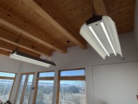
I converted two hard-wired pendant fixtures to outlets in my library/studio earlier this year. The previous owners used the pendant spotlights when it was a painting studio. I needed to use two ancient 48" fixtures I converted to LED. I wanted to keep plug-in rather than hard wire them, so there's what I did.

It took some hunting to find outlet plates that would fit on the ears of an octagonal or circular box. The shallow box took a 4" diameter/1/2" thick spacer to give enough volume in the recessed shallow box to mount the outlets.

i-P28dCVN-X5.jpg
i-HdB6RMt-X5.jpg
i-2FK9xdS-X5.jpg
i-wnz7XQ2-X5.jpg
i-zb3Smsc-X5.jpg

81iUjQL7YPL._AC_SL1500_.jpg
 
Last edited:

dave*99

Well-known member
Joined
May 5, 2009
Messages
4,380
Location
Coastal NJ
If that's the case, then the sketch is incomplete or wrong in other ways. Needs another cable in the ceiling outlet to run over to the flood.

His sketch makes more sense with the 2g box receiving power first instead of running two cables between the same two box locations.

PICS of each box clearly showing the cables and conductors in each. Also switches how connected.
I’m trusting his tests results more than his diagrams. Your comments are sensible. Hopefully he can make sense of the discussion and enlighten us.
 
OP
A

aragno

Active member
Joined
Oct 31, 2021
Messages
28
I really appreciate the feedback and apologies for the slow response- 3 kids keep us busy.
Power could be coming into the ceiling box from either cable. Unsplice both blacks in the ceiling outlet. Leave neutrals spliced. Which cable brings constant 120 into the box? (measure from black to neutral on both cables) It could be from either one. (red is usually switched, but it doesn't have to be) The 3 wire cable connects to the switch box. Switched power is probably on the red. Check it by flipping the switch to each position and measure red - neutral.

Answer these q's first so we don't have to discuss write a bunch of needless scenarios.
I have measured voltage on both black wires. 120v on one, 0v on the other.
Red is switched in the ceiling from the switch on the wall (2g box)
See updated graphic below with "test" results.
Ok, didn't see that as I was only responding to where your ping led me to. Ok, so post 21 is pretty close to what I suggested in post 28.

Always good to have a roadmap.

So it looks like power comes into the 2g box on jacket #2 or #3.
I don't think jacket #2 in the switch box is the same as the dwg indicates as jacket #2 in the ceiling outlet. Lets rename jacket #2 in the ceiling outlet as jacket #4. Jacket #4 goes to the floodlight.
Jacket #1 brings 2 switched legs into the ceiling outlet box along with a neutral.

Either jacket #2 or #3 provides power into the 2g box. Whichever one isn't the cable from the panel is bringing 120v out of the 2g box to other stuff. It's just daisy-chained in the 2g box.

If you want to gfci protect the ceiling recept (and floodlight) from the 2g location with a gfci dead front or gfci recept, you have to install it upstream of wirenut #2. Both switch's power has to come from the load side of the gfci. The neutral for jacket #1 has to go onto the load side of the gfci.

Either bust out the 2g box and put in a 3g or change the 2 single pole switches to a tandem switch device to make room the gfci device.

Or just change the cb to gfci version and cover the entire circuit without changing anything in the 2g box..
I've renamed the Jacket #2 in the ceiling to Jacket #4 and the other one to Jacket #5.
See updated graphic below with "test" results.

If that's the case, then the sketch is incomplete or wrong in other ways. Needs another cable in the ceiling outlet to run over to the flood.

His sketch makes more sense with the 2g box receiving power first instead of running two cables between the same two box locations.

PICS of each box clearly showing the cables and conductors in each. Also switches how connected.
I reviewed my sketch and it appears accurate. I went wire by wire to confirm.
Getting clear photos is not going well due to limited space and lighting... it's so confined it looks like a rat's nest when I take a photo.


garage-wiring-findings-infographic-final (2).jpg
 

dave*99

Well-known member
Joined
May 5, 2009
Messages
4,380
Location
Coastal NJ
I’m thinking I misread post 26. It does look like power hits switch box first. So a GFCI there can work.
 

dscheidt

Well-known member
Joined
Apr 26, 2017
Messages
2,964
I really appreciate the feedback and apologies for the slow response- 3 kids keep us busy.

I have measured voltage on both black wires. 120v on one, 0v on the other.
Red is switched in the ceiling from the switch on the wall (2g box)
See updated graphic below with "test" results.

I've renamed the Jacket #2 in the ceiling to Jacket #4 and the other one to Jacket #5.
See updated graphic below with "test" results.


I reviewed my sketch and it appears accurate. I went wire by wire to confirm.
Getting clear photos is not going well due to limited space and lighting... it's so confined it looks like a rat's nest when I take a photo.


garage-wiring-findings-infographic-final (2).jpg
If I follow the drawings correctly, power enters the ceiling box on the 14/2, the neutrals are spliced together using the device (sigh), the black from the 14/2 and 14/3 are spliced, and the receptacle is fed by the red from the 14/3.

So, you can't put a GFCI in the wall with the switch, because the neutral on the receptacle is ahead of the GFCI, and it would trip every time there was a load on the receptacle. So the only reasonable way to protect the receptacle is with a GFCI breaker. To do otherwise, you'd need to run another piece of romex from the receptacle outlet to the switch. (This is why people advocate for conduit, you'd just run another conductor in the existing pipe, ´and be done.)
 
To avoid these ads, REGISTER NOW!
Top Bottom