To avoid these ads, REGISTER NOW!

Craftsman Drill Press

OP
F

FrankLee

Well-known member
Joined
Sep 13, 2010
Messages
3,555
Location
seMI, 48317
Powr-Kraft Motor 84 DP 4551 - cont'd

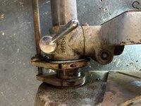
Because of how this motor was assembled, the switch-side end cap was much more difficult.

I could not push the rotor through the bearing on the switch side, so I had to loosen the end cap to see what was going on.

IMG_6217.JPG IMG_6219.JPG

This is very different than anything I've ever seen before.
IMG_6221.JPG IMG_6222.JPG

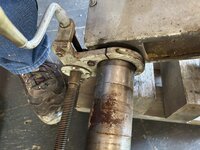
I had to start removing parts with very little space...
IMG_6224.JPG IMG_6225.JPG IMG_6227.JPG IMG_6229.JPG

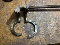
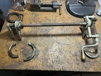
and discovered that the bearing was secured to the end cap with screws and washers. But why didn't the rotor shaft press out of the bearing?
IMG_6231.JPG
 
Last edited:
To avoid these ads, REGISTER NOW!
OP
F

FrankLee

Well-known member
Joined
Sep 13, 2010
Messages
3,555
Location
seMI, 48317
Powr-Kraft Motor 84 DP 4551 - cont'd

I was able to remove one screw, but the other screw slot got messed up. This was the last screw to remove, so I had nothing to lose by forcing the bearing past the screw.
IMG_6235.JPG IMG_6239.JPG
Now that all major components were separated, it was time to pull the bearings off the rotor. A sleeve was installed on the outboard side of both bearings. It seemed like it took every bit of my 10 ton Proto puller to remove the bearing and sleeve on the governor side of the rotor.

IMG_6240.JPG IMG_6241.JPG
The bearing on the fan side would not budge even after Liquid Wrench and plenty of heat. The outer race eventually shattered and pieces flew across the shop.

IMG_6244.JPG IMG_6245.JPG IMG_6246.JPG

I had to cut slits in the sleeve with a Dremel and use a nut splitter to crack it loose. The bearing seemed to be a slip fit.

IMG_6255.JPG

I don't know what they used to install those sleeves, but I think they were pressed on tightly. I'm also not sure what purpose they served since the outer races of both bearings were fully seated in their bores in the end caps
 
Last edited:
OP
F

FrankLee

Well-known member
Joined
Sep 13, 2010
Messages
3,555
Location
seMI, 48317
Powr-Kraft Motor 84 DP 4551 - cont'd

The bearings are off. These are part number 88013, 13mm x 32mm x 0.394mm with an extended inner race on each side. I ordered them from Accurate for a decent price, but ugh, that was not a good experience.

IMG_6252.JPG


Here is the switch-side end cap. It is quite full.
IMG_6470.JPG

There are two 70-95 mfd capacitors wired in parallel. These capacitors are quite small; 1.125" diameter by 2.625" long. I could not find exact replacements, so anything new would have to be installed externally.
IMG_6248.JPG

The F/R switch is a Cutler-Hammer part, but no specs printed on it. It is pre-wired with eight terminals and four wire leads. I could not find a replacement for this either. The toggle is bent a bit, but it still works fine.
IMG_6467.JPG

The terminal board has two switch contact points. The thermal switch is integrated onto the board.
IMG_6472.JPG IMG_6461.JPG

This stamped metal piece has the matching contact points and rocks on the board to open and close the capacitor circuit. More on that later.
IMG_6222.JPG


So, the new bearings arrived... finally, and I reassembled the motor. It looks and runs great, except...
IMG_6675.JPG
 
Last edited:
OP
F

FrankLee

Well-known member
Joined
Sep 13, 2010
Messages
3,555
Location
seMI, 48317
Powr-Kraft Motor 84 DP 4551 - cont'd

After assembling the motor, I installed it onto a Craftsman 100 drill press. I switched it on and off several times, forward and reverse. All is good.

I switched it on once more and nothing... no start. ****! I turned the rotor by hand and it came to life. This is exactly what the seller described.

I mulled this over for a few days trying to figure out how I'm going to install a new capacitor.


Back to diagnosis... Those two switch contacts on the board are accessible from the outside.
IMG_6744.JPG

I checked continuity and got a good reading.
IMG_6746.JPG

But when I rotated the shaft, the circuit would open on every rotation. I'm onto something.

I cracked open the motor again and inserted the rotor into the end cap.
IMG_6748.JPG

The photo below shows how the governor and switch interact with each other.

A felt disk with centrifugal weight (red arrow) is attached to the rotor with a spring and pin. It rides on the cone of the stamped metal switch lever.

With power off, the felt disk is at the top of the cone pressing down the contacts (orange arrows) closing the cap circuit. At this point, the contacts act as fulcrum points and the spring on the bolt at the far right is compressed.

When power is switched on, the weight is flung out off the cone. The spring under the small screw at the right lifts the switch lever off the contacts and opens the cap circuit. The small divots (green arrows) now act as fulcrum points.

When power is switched off, the felt disk is pushed sideways against the cone and lowers the cone which closes the cap circuit for the next start.
Powr-Kraft motor cent switch c.jpg


Below is a video showing this in action.

In my case, the switch lever mechanism undulates as the rotor turns. Somehow, the cent circuit opens for a short duration on every rotation. Each time the motor did not start, the felt disk landed on that open-circuit spot from previous stop. To fix this, I simply bent the cone up slightly. So simple.

The real key to solving this was to insert the rotor into the end cap and observe how it operates.

IMG_6748.JPG
 
Last edited:
OP
F

FrankLee

Well-known member
Joined
Sep 13, 2010
Messages
3,555
Location
seMI, 48317
Powr-Kraft Motor 84 DP 4551 - cont'd

I don't know who manufactured Powr-Kraft motors, but they are among the nicest looking of the era. Those beauty rings serve no other purpose than aesthetics. Other models have nice details also. Despite their appearance, I am not a fan of that goofy centrifugal switch design.

IMG_6718.JPG
 
Last edited:
OP
F

FrankLee

Well-known member
Joined
Sep 13, 2010
Messages
3,555
Location
seMI, 48317
So, these 115.7575 1/2 hp cast iron grinders came equipped with rather nice Vimco gooseneck lamps. The shades are bakelite and some of the lamp socket housing and fittings are solid brass. Below is the Vimco lamp from my 115.7575#3. They clean up very nicely and rival the Delta machine lamps.
IMG_0374.JPG

These lamps are somewhat difficult to thoroughly polish because the brass components of the assembly cannot be disassembled.

However, with 115.7575#4, I discovered that some of the brass parts are both threaded together and soldered. Apparently, the solder failed on this one; likely from the PO turning the shade too much.
IMG_6488.JPG IMG_6828.JPG


This prompted me to take a closer look at the assembly on 115.7575#5. I used a torch to dismantle these.

IMG_6827.JPG IMG_6825.JPG IMG_6826.JPG


This made it much easier to buff and polish all brass parts.
IMG_6829.JPG IMG_6830.JPG IMG_6831.JPG IMG_6833.JPG


I'm not sure whether I'll re-solder them back together or just use a thread locker.


Now, if I could only find someone to 3D print a couple shades.
IMG_6679.JPG
 
Last edited:
OP
F

FrankLee

Well-known member
Joined
Sep 13, 2010
Messages
3,555
Location
seMI, 48317
I really like these 90-degree Vimco lamp sockets. They adjust and swivel very easily and the light from a PAR16 led bulb targets the tool rests perfectly.

I swapped out my Woodward gooseneck lamp with this Vimco gooseneck lamp. Because the bakelite shades were fubar, I just painted the back of the LED bulb.
IMG_5446c.JPG IMG_6934.JPG IMG_6935.JPG
 
Last edited:
OP
F

FrankLee

Well-known member
Joined
Sep 13, 2010
Messages
3,555
Location
seMI, 48317
I picked up this drill press yesterday, DP#147. I knew there were missing parts and, because of his $30 asking price, there must be more issues.
471981251_465954406549384_201471791706074377_n.jpg

I wasn't wrong, but it's a very interesting case study.

It's a model 103.24501 from the early '60s. It was repainted twice.
There is an asset tag on the front edge of the table from H.I.I., a U.S. defense contractor/ship builder.

The motor is not original to the machine; its date code is 6 56. It's a model 115.19801, 1/2 hp, 3450 rpm which is inappropriate for a drill press. It runs decently, but is typically dirty, loud and needs a new cord. I do believe it will clean-up nicely.

IMG_0023.JPG


missing oem parts:
  • feed stop rod and rapid-adjust collar
  • feed return spring
  • motor mount stud and clip parts
  • one feed handle rod/knob
  • knurled pin for the spring/pinion/hub
  • quill lock assembly
  • chuck key
  • rubber and steel spindle washers
    IMG_0131.JPG


fubar/modified/wtf parts:
  • Because the oem spring was missing, a custom spring-return system was added.
    The feed stop bracket was repurposed as an anchor on the quill for a long extension spring. The other end of the spring was attached to a steel plate resting inside top of the head casting.
    IMG_0028.JPG IMG_0029.JPG IMG_0031.JPG
    IMG_0030.JPG IMG_0032.JPG

  • Also because the oem spring was missing, a groove was cut into the pinion shaft and a hole was drilled/tapped on the right side of the head casting for a dog-point set screw... very similar to the earlier drill presses.
    IMG_0068.JPG IMG_0069.JPG

  • Both holes in the hub for the spring/pinion pin are cracked and a large crack from the pinion shaft. A worm clamp held it together.
    IMG_0092.JPG IMG_0180.JPG

  • The gear end of the pinion shaft was tapped and some kind of plug inserted. I'm not sure what was intended here. I tried to remove it, but it wouldn't budge.
    IMG_0094.JPG

  • Both spindle pulley retaining screws were bent/damaged. I don't understand how this could happen on a 150 with the snap ring on the lower quill. One screw head slot was damaged and the remaining portion of the screw is still stuck in the head casting.
    IMG_0058.JPG IMG_0081.JPG

  • The head trim panel is scraped and worn.
    IMG_0089.JPG IMG_0086.JPG IMG_0085.JPG

  • The chuck jaws were difficult to extend and remove. I believe the nose of the chuck body is mushroomed inward.
    IMG_0112.JPG


good parts:
  • There are lots of extra holes in the head casting, but there are no cracks.
  • There are lots of intended and unintended holes in the table, but it is still good.
  • The base and column are very rusty, but usable.
  • head and table lock assemblies
  • feed stop bracket
  • two feed handles/knobs
  • quill
  • spindle (runout is 0.005", but I'm confident I can improve that)
  • spindle pulley
    IMG_0116.JPG IMG_0117.JPG IMG_0122.JPG


bonus parts:
  • a heavy-duty Allen Bradly On/Off switch was included
  • a Cutler-Hammer keyed On/Off switch with a Briggs & Stratton key was included
    IMG_0035.JPG IMG_0125.JPG IMG_0127.JPG
 
Last edited:
OP
F

FrankLee

Well-known member
Joined
Sep 13, 2010
Messages
3,555
Location
seMI, 48317
So this machine is just nasty. It looks like the base spent some time under water.

471981251_465954406549384_201471791706074377_n.jpg IMG_0146.JPGIMG_0148.JPG


I wasn't so sure it could be extracted, but here's how I got the column out of the base.

I have a few Proto pullers that are all threaded 9/16-12. I used a 36", 9/16" threaded rod through the column, a couple of old column collars and large washers to force the base UP the column. It worked rather well. It also works on a floor-standing drill press using a second 36", 9/16" all-thread and a coupling nut.

IMG_0151.JPG IMG_0149.JPG IMG_0152.JPG IMG_0153.JPG


A wider collar for part two.

IMG_0156.JPG IMG_0157.JPG

After the base is far enough "up" the column, the rustiest stuff was cleaned off and the base could be removed "down" and off the column.

IMG_0162.JPG


This will sit until spring when I can use electrolysis to remove the rust. I think this is too badly rusted for citric acid.

IMG_0168.JPG
 
Last edited:
OP
F

FrankLee

Well-known member
Joined
Sep 13, 2010
Messages
3,555
Location
seMI, 48317
I also dismantled, cleaned, lubed and reassembled the chuck. It didn't work any better and is beyond saving.

IMG_0169.JPG


I was able to reduce run-out on the spindle taper from ~0.005" ...


... to under 0.001".


I cleaned the spindle, but I've never seen splines worn so badly. The splines in the spindle pulley do not have any obvious wear. :dunno:

IMG_0175.JPG IMG_0122.JPG

:dunno:
 
Last edited:

y'sguy

Well-known member
Joined
May 1, 2010
Messages
1,308
Location
Tulsa, Oklahoma
Nice work, Frank. It makes one appreciate the good ones that still may be around. There is a floor model DP for sale on MP about 50 miles from me. Asking 200 and it is sitting outside at a flea market-type place. For some reason, I still think I want a floor model. My table model looks and works fine for all I do. The floor model even at 100 would be questionable to me at this point.
 

Outlawmws

Well-known member
Joined
Aug 9, 2011
Messages
39,128
Location
The Badlands
Nice work, Frank. It makes one appreciate the good ones that still may be around. There is a floor model DP for sale on MP about 50 miles from me. Asking 200 and it is sitting outside at a flea market-type place. For some reason, I still think I want a floor model. My table model looks and works fine for all I do. The floor model even at 100 would be questionable to me at this point.
5-6 ft of the right size tubing and you have a floor model from your bench model...
 
OP
F

FrankLee

Well-known member
Joined
Sep 13, 2010
Messages
3,555
Location
seMI, 48317
Frank, that wear is epic. Any indication during use?
I'll have it ready to test later this afternoon.

The wear begins near 3" from the spindle collar, so into the deeper feed range.
IMG_0182.JPG
I drilled a 1" hole through a piece of 3/4" plywood with a spade bit. There were no issues with the worn spindle.

I did have an issue with the feed return spring and the pinion retaining screw. I had this issue a while back and described the problem and solution in the link below. My resolution on this dp was slightly different, but the gist was the same.
https://www.garagejournal.com/forum/threads/craftsman-drill-press.227480/page-131#post-10427994
 
Last edited:
To avoid these ads, REGISTER NOW!
OP
F

FrankLee

Well-known member
Joined
Sep 13, 2010
Messages
3,555
Location
seMI, 48317
A Better(?) Way to Tension the Feed Return Spring

I did have an issue with the feed return spring and the pinion retaining screw. I had this issue a while back and described the problem and solution in the link below. My resolution on this dp was slightly different, but the gist was the same.

So, I installed the spindle pulley assembly and the quill/spindle assembly from DP#147 into DP#146.

As I mentioned above, after tensioning the spring, the feed return was sluggish. The quill would return halfway up and then stop. Increasing the tension did not help feed return. I also had this issue on DP#137, a 12-1/4" Dunlap and figured out why it happened. However, the solution I used on DP#137 would not work on an 80, 100 or 150.


This morning, I was able to recreate the sluggish feed return on DP#146.

I released the tension and re-tensioned the spring without making any adjustments. Notice how far to the left the spring sits.
IMG_0256.JPG IMG_0257.JPG

This video shows the problem. The spring is pressing the pinion so tightly against the pinion retaining screw that the quill gets "stuck".


How I fixed it:
  1. I released the tension on the spring and removed the tension knob.
  2. I grabbed the tang of the spring with needle-nose pliers and stretched the spring out about 1/2".
    IMG_0260.JPG

  3. I inserted a thin piece of metal strap into the spring to prevent it from retracting.
    IMG_0261.JPG

  4. I re-inserted the knob and turned it CCW about a half turn and locked the knob. Notice that the spring is now bottomed-out into the prongs.
    IMG_0262.JPG IMG_0263.JPG

  5. I removed the metal strap and continued to tension the spring.
    IMG_0264.JPG IMG_0265.JPG

This video shows the much improved feed return.


This technique will work on all 12-1/4", 13-1/2" and 15-1/2" drill presses with the external spring tension knob. I'll be using this spring tension method on all future machines.

I used this piece of ~0.018" ss strapping, but a feeler gauge, a 6" machinist rule, a hack saw blade or something of similar thickness will work well.
IMG_0267.JPG
 
Last edited:
OP
F

FrankLee

Well-known member
Joined
Sep 13, 2010
Messages
3,555
Location
seMI, 48317
HEADS-UP!

I wish I had the energy (or help) to get this one with a table lift and several extra goodies. Someone should grab it.

473218448_1096036155593284_3935395656065502305_n.jpg

Well, I tried, but I couldn't resist.

DP#148 is a Craftsman-branded Atlas machine in rough shape. The model number is 101.24830. The motor is a 115.6962 with date code J1 47.

Besides the H&TL(#10) and the alfa-class belt cover, it came with an MSA, a Dunlap vise, a mortise hold-down, a column collar and a generic 4-step cone pulley.


1/21/2025

I have the head cleaned and reassembled.
IMG_0354.JPG IMG_0355.JPG IMG_0357.JPG

The MSA is sale pending.
IMG_0339.JPG

The H&TL came apart nicely.
IMG_0364.JPG IMG_0365.JPG IMG_0366.JPG IMG_0367.JPG

I think I'm going to re-paint the H&TL and swap it onto my keeper drill press.
 
Last edited:
OP
F

FrankLee

Well-known member
Joined
Sep 13, 2010
Messages
3,555
Location
seMI, 48317
DP#148 came with the very common Packard 115.6962 motor. It has a date code of J1 47.
IMG_0372.JPG

This morning, I dismantled the motor. I gotta say that this is the strangest 6962 motor I've ever seen.

The bottom cover is gray. The bearing felt covers and the switch shield are painted black... a combination I've never seen.
IMG_0402.JPG

All eight bearing cover machine screws have round heads instead of fillister heads. I've never seen that before.
IMG_0411.JPG

There were four shim/spacer washers on the switch side of the rotor shaft
IMG_0407.JPG

There's no evidence to believe that these parts did not come like this from the factory.


There were two spring washers on the fan end. I presume they were misaligned and got deformed when the bearing cover was installed. They were stuck together as shown when I pulled them off the shaft.
IMG_0408.JPG IMG_0410.JPG
The bearing shield and felt cover on the switch side were deformed and bulging out. I have seen this before, but not to this degree.
IMG_0403.JPG IMG_0405.JPG IMG_0406.JPG

The bearing was protruding from the end cap and seized in that position. The shaft slid out of the bearing before the bearing was removed.
IMG_0380.JPG

Just when you think you've seen it all, you haven't.
 
OP
F

FrankLee

Well-known member
Joined
Sep 13, 2010
Messages
3,555
Location
seMI, 48317
I gotta say that this is the strangest 6962 motor I've ever seen.
I got the motor straightened out and back together with good parts. It runs great!

IMG_0460.JPG IMG_0461.JPG


The MSA is sold which recouped my entire investment in the rest of the drill press and accessories.


The table lift is coming along nicely.

IMG_0303.JPG IMG_0421.JPG
IMG_0437.JPG IMG_0451.JPG
IMG_0366.JPG IMG_0436.JPG


The Dunlap vise and mortise hold-down/fence are cleaned.

IMG_0281.JPG IMG_0463[1].JPG IMG_0462[1].JPG
 
Last edited:
OP
F

FrankLee

Well-known member
Joined
Sep 13, 2010
Messages
3,555
Location
seMI, 48317
No more progress on the lift this week... still too cold to paint.

I installed the motor on the head assembly. It tested great.

I also got the column done; extracted, de-greased, de-rusted and polished. The column extraction from the base was the typical pita on these Atlas machines. There are some areas of pitting near the bottom, but it cleaned up well otherwise.

I'll need my angle grinder with a stripping disk to clean the base for painting... another outdoor project delayed by weather.

IMG_0494.JPG IMG_0495.JPG IMG_0496.JPG IMG_0497.JPG

after 24 hr citric acid bath
IMG_0498.JPG IMG_0502.JPG

sanding/polishing on the lathe
IMG_0508.JPG IMG_0510.JPG IMG_0511.JPG

IMG_0514.JPG


It's not directly related to DP#148, but this week I bought a new single shelf from FB for my parts rack. It was getting out of hand and needed some reorganization.

IMG_0516.JPG
 
Last edited:

RHJO51

Well-known member
Joined
Feb 27, 2015
Messages
242
Location
Red Hook, NY 12571
Hi Folks, I posted this over on OWWM but thought I'd share here too.

I needed another Craftsman drill Press like I need another hole in my head, but I saw an ad for a Craftsman 100 series bench top drill press which included a interesting table lift. $50. There are 3 two piece collars and a retainer that is attached to the table. The top collar assembly was attached to the head by two bolts. The unit seemed to work fine but I didn't want to move it much as the works was pretty gunked up. No markings that I can see. I thought it was an after market item but now thinking custom made? It's very nicely made. If custom someone put a lot of work into this one. There was also a safety collar thats the same two piece set up, Brass or bronze lift handle. Thoughts? Thanks!
 

Attachments

  • IMG_1483.JPG
    IMG_1483.JPG
    703.7 KB · Views: 18
  • IMG_1485.JPG
    IMG_1485.JPG
    678.5 KB · Views: 17
  • IMG_1486.JPG
    IMG_1486.JPG
    748.9 KB · Views: 14
  • IMG_1487.JPG
    IMG_1487.JPG
    807.9 KB · Views: 14
  • IMG_1488.JPG
    IMG_1488.JPG
    789.1 KB · Views: 19
OP
F

FrankLee

Well-known member
Joined
Sep 13, 2010
Messages
3,555
Location
seMI, 48317
Hi Folks, I posted this over on OWWM but thought I'd share here too.

I needed another Craftsman drill Press like I need another hole in my head, but I saw an ad for a Craftsman 100 series bench top drill press which included a interesting table lift. $50. There are 3 two piece collars and a retainer that is attached to the table. The top collar assembly was attached to the head by two bolts. The unit seemed to work fine but I didn't want to move it much as the works was pretty gunked up. No markings that I can see. I thought it was an after market item but now thinking custom made? It's very nicely made. If custom someone put a lot of work into this one. There was also a safety collar thats the same two piece set up, Brass or bronze lift handle. Thoughts? Thanks!
I saw it over there. My swaq is also a one-off custom home/shop-made piece.

IMO, it's somewhat crude for a mass-produced piece, but was well made.
Reasons I think it's a custom piece:
  • the crank/pinion shaft supports are bolted on
  • parts are bolted to the head casting and the table support
  • the flanges are screwed to the column clamps
On the other hand, this is a rather sophisticated feature. It allows the table to turn from side-to-side.
IMG_1488.JPG

Did the seller offer any history of the machine?

What's with that lever handle on the right side of the head casting?
 
Last edited:

RHJO51

Well-known member
Joined
Feb 27, 2015
Messages
242
Location
Red Hook, NY 12571
Hi, thanks for the response. Unfortunately the PO didn’t have any history, I believe he got th DP as part of a clean out. That odd lever on the side of the head was used for tightening the motor mount. The DP is missing the original mount and the PO has the motor mounted on some kind of plate - not sure why. I need to take a better look. When is saw the DP for sale I thought I could put this lift on a nice 150 I refurbished several years ago. I’m not as young as I used to be and I thought having the lift would be helpful. I had purchased another 150 that had a very nice Atlas lift but it turned out to have a trashed zamac gear in the housing so that lift is on the shelf… I need to think if it makes sense to try and fit this new lift on the 150 or just refurb this nice 100 and move it on.
 
OP
F

FrankLee

Well-known member
Joined
Sep 13, 2010
Messages
3,555
Location
seMI, 48317
This morning, I went to check out this 150 at an estate sale. It was marked $150 on the first day of the sale, not terrible, but the feed stop assembly was missing, the motor was not original and the original chuck was replaced with an import keyless. I didn't buy it.

1740246095621.jpeg 1740246033033.jpeg

I found the original chuck elsewhere, but could not find the feed stop assembly.

I did hit the estate sale lottery and found a new, unopened can of Johnson Paste Wax (bottom photo) for $4. LoL!

Capture.JPG 1740497051050.png


1740246214300.jpeg
 

Attachments

  • 1740497028811.png
    1740497028811.png
    1 MB · Views: 9
Last edited:

Gimourisgod

Member
Joined
Oct 13, 2020
Messages
8
Location
Brother's Barn
Looking for the quill return spring for a Craftsman Model #103.23640, 13.5" press. Found a guy on Ebay who has what looks like the same spring, listed as part #22623 in the original exploded parts diagram, but he's not sure it will fit in my press. The existing one looks just like the diagram, with a loop at one end and a flat leg at the other that gets engaged by the return spring tension knob. Anybody got a lead on where I could find one?
k0D5AhQ.jpg

Yiq3Hjs.jpg
 
OP
F

FrankLee

Well-known member
Joined
Sep 13, 2010
Messages
3,555
Location
seMI, 48317
Looking for the quill return spring for a Craftsman Model #103.23640, 13.5" press. Found a guy on Ebay who has what looks like the same spring, listed as part #22623 in the original exploded parts diagram, but he's not sure it will fit in my press. The existing one looks just like the diagram, with a loop at one end and a flat leg at the other that gets engaged by the return spring tension knob. Anybody got a lead on where I could find one?

The 12-1/4", 13-1/2" and early 15-1/2" drill presses all use the loop and tang spring. The 12-1/4" and the 15-1/2" drill presses use the identical spring. The oem spring for the 13-1/2" drill press is longer and less common.

However, the 13-1/2" drill press can be slightly modified to accept the shorter spring. See my quote below.

I do have a shorter loop & tang spring available.


QUOTE="FrankLee"

02/02/2021


Feed Return Springs

If you've been following along, you know that these classic Craftsman drill presses use a coil torsion spring for feed return. The smaller 12-1/4" drill press and the larger 15-1/2" drill press both use the same 4" spring. The mid-size 13-1/2" drill presses use a 5" spring.

I believe that many more 15-1/2" drill presses were sold than the 13-1/2" models. That means that fewer good used parts are available and therefore, more difficult to come by for the mid-size machines.

I received a question overnight asking whether a 4" spring will fit in a 13-1/2" machine. The technical answer is no, but it is not difficult at all to make it work.

Below is a picture of a pinion assembly from a 12-1/4" machine. The spring loop is held in place with a 3/16" x 1-1/4" long spring pin. The spring pin hole is 4-3/16" from the end of the pinion shaft.


1741040290512.png

The pinion assembly from a 13-1/2" machine is at the bottom of the picture below. The spring loop is held in place with a loose fitting solid pin through the small portion of the end knob. The pin is held captive in the knob when the knob is inserted into the end of the pinion shaft.

1741040407332.png

It's a simple process to drill a new 3/16" hole for a spring pin through the pinion shaft of a Craftsman 13-1/2" drill press. Moving the pin and using the shorter spring has no effect on the feed handle rod.

1741040517583.png
The 4" spring will work just fine on a Craftsman 80 and may be easier to find.

1741040608147.png
 
Last edited:

Hoorn

Well-known member
Joined
May 19, 2020
Messages
1,140
Location
Glendora, CA
Deals can still be had. I am second in line and don't believe first in line will pass this one up. This 100 literally has the trifecta of accessories.

It appears the vari-slo may have some issues, particularly with the "screw" handle, and the manner in which the lift is mounted makes me wonder if the gears have disintegrated, but at that price I would take a chance, no brainer.

The XY table looks very complete.

Screenshot_20250315-123819~2.png

Screenshot_20250315-123831~2.png

Screenshot_20250315-123836~2.png

Screenshot_20250315-123842~2.png
 
OP
F

FrankLee

Well-known member
Joined
Sep 13, 2010
Messages
3,555
Location
seMI, 48317
Deals can still be had. I am second in line and don't believe first in line will pass this one up. This 100 literally has the trifecta of accessories.

It appears the vari-slo may have some issues, particularly with the "screw" handle, and the manner in which the lift is mounted makes me wonder if the gears have disintegrated, but at that price I would take a chance, no brainer.

The XY table looks very complete.
Wow!

It looks like the clamping pad is missing from the V-S. The head lock cylinders were swapped with the table lock. The screw cover may be missing from the X-Y. Lift is unknown. Not the best repaint. Nice vise on the X-Y. Yep, worth the risk.
 
To avoid these ads, REGISTER NOW!
Top Bottom