To avoid these ads, REGISTER NOW!

Craftsman Drill Press

endangeredspecies

Well-known member
Joined
Apr 11, 2022
Messages
264
Location
SF Bay Area
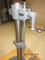
Finally back working in the shed. I've started building my press-adjacent workbench, which got me looking at the press.
The Headstock Lock Handle was mounted on the wrong side, causing interference between it, the feed handles, and an add-on power switch.

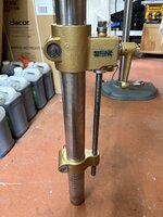
One of the quill / feed handles was perfect. One was very slightly bent. One was bent to the point where I could barely get it out. I polished up the two decent ones.
I'm afraid the really bent one suffered from inadequate heat or excessive force (or both) in the straightening exercise.
So, now I'm out a 27618 Feed Handle.

I have reached out to oldironowner to see if he's still doing them, but it doesn't look like he's posted about it since 2022.

Failing that - anybody else have a line on a supplier single, replacement, 3/8" thread, feed handle?
I was able to remove the black (18916) knob without any damage, so just need the single handle.
But willing to buy a set of 3 complete ones, if that's what it takes to get up-and-running.

cA3AXZ9.jpg

POBWrUk.jpg
 
To avoid these ads, REGISTER NOW!
OP
F

FrankLee

Well-known member
Joined
Sep 13, 2010
Messages
3,555
Location
seMI, 48317
Can you drill/tap the main bar, and install a stud?
I had a friend fix one for me a while back.
IMG_0552.JPG IMG_0553.JPG IMG_0554.JPG

@endangeredspecies, You might also consider converting to the later hub and handles with 1/2-13 threads. These parts show up on ebay regularly.


BTW, you really need to fully seat your feed stop bracket onto the quill. As it is now, the spindle pulley is getting bumped by the spindle collar. The quill bumper is not contacting the head casting as it should and the thrust collar is not visible at all.
cA3AXZ9.jpg
Check this post:
https://www.garagejournal.com/forum/threads/craftsman-drill-press.227480/page-84#post-8421465
 
Last edited:

endangeredspecies

Well-known member
Joined
Apr 11, 2022
Messages
264
Location
SF Bay Area
Thanks so much, guys!

Thanks for the picture, FrankLee. I just couldn’t envision what outlawmws was suggesting.

Outlawmws, I don’t have a lathe. The only other tool I own which could possibly help me drill and tap that handle is this drill press, which I’m still rebuilding.
Now you’ve got me thinking about how I could even fab up a jig that would get me that kind of precision. For the materials needed, time it would take, and fact that it would probably take me 2 tries (and I have only 1 broken handle), I think I’ll be better off buying the set from oldironowner. Who did respond to my inquiry.
 
Last edited:

endangeredspecies

Well-known member
Joined
Apr 11, 2022
Messages
264
Location
SF Bay Area
I had a friend fix one for me a while back.
IMG_0552.JPG IMG_0553.JPG IMG_0554.JPG

@endangeredspecies, You might also consider converting to the later hub and handles with 1/2-13 threads. These parts show up on ebay regularly.


BTW, you really need to fully seat your feed stop bracket onto the quill. As it is now, the spindle pulley is getting bumped by the spindle collar. The quill bumper is not contacting the head casting as it should and the thrust collar is not visible at all.
cA3AXZ9.jpg
Check this post:
https://www.garagejournal.com/forum/threads/craftsman-drill-press.227480/page-84#

I had a friend fix one for me a while back.
IMG_0552.JPG IMG_0553.JPG IMG_0554.JPG

@endangeredspecies, You might also consider converting to the later hub and handles with 1/2-13 threads. These parts show up on ebay regularly.


BTW, you really need to fully seat your feed stop bracket onto the quill. As it is now, the spindle pulley is getting bumped by the spindle collar. The quill bumper is not contacting the head casting as it should and the thrust collar is not visible at all.
cA3AXZ9.jpg
Check this post:
https://www.garagejournal.com/forum/threads/craftsman-drill-press.227480/page-84#post-8421465

Wow. What a level of detail and concern.
The rebuild is just barely started. I’ll definitely check the link and make sure I get this right.
Thanks again!
 
OP
F

FrankLee

Well-known member
Joined
Sep 13, 2010
Messages
3,555
Location
seMI, 48317
About 115.6962 motor re-assembly for drill presses...

Because of how the "ON/OFF" switch plate was printed, there really is only one way to install it and the switch; "ON" to the left and "OFF" to the right.
IMG_0138.JPG

The switch plate could be rotated or flipped upside down, but it wouldn't look correct. The switch plate could also be replaced with a generic version that can be oriented either way.
IMG_4151.JPG

In the factory configuration, with the motor installed on a drill press with the switch on the right and "OFF" facing down, the terminal end would be up. However, I don't recall ever seeing factory-set motor rotation direction specified anywhere.
Screenshot 2025-04-09 103235.jpg

I see motors on drill presses all the time with the fan side up AND switch on the left side with the "OFF" position facing up. That just not not seem natural to me; "OFF" should be down. It is likely is due to how the rotation was set at the factory. Buyers likely installed the motor using the factory rotation setting without really thinking about it or realizing rotation could be reversed by swapping the two wires on the terminal board.

I always(?) install these motors on a drill press with the terminal end down. I re-orient the base so the switch is on the right so the OFF position of the switch is down. Being right-handed, the switch on the right side is my preference.
IMG_0771.JPG

This sometimes requires reversing motor rotation. I orient the center band so the badge is facing the switch. So, when the motor is sitting on the bench, OFF is pointing to the right and the terminal side is to the right of the switch.


There are a few advantages to rotating the motor base:
1) With an MSA or Vari-Slo and the pulley inverted, the terminal cover interferes with the inverted pulley. With fan side up, the pulley sits as low as possible (my preference).
IMG_0878.JPG IMG_0883.JPG

2) With an MSA or Vari-Slo, the pulley would also cover the thermal switch. It would be a pita to have to remove the pulley to reset the thermal switch. Yeah, a rare occurrence, but still...
IMG_0879.JPG IMG_0880.JPG

3) I prefer it that way for looks.

I have messed up at times when reassembling a motor, but then I use a foot switch and leave the motor switch in the ON position:
52082646471_9d0fef548d_k.jpg


It's interesting to note that the 1948-1950 catalogs show the motor oriented such that the switch is on the right side and presumably OFF is pointing down. Subsequent catalogs are not clear, but the bottom edge of the badge is visible, but no toggle switch. The image below is from the 1948 catalog.
1756478185849.png
 
Last edited:

Modagger

Well-known member
Joined
Aug 11, 2021
Messages
111
Location
Hamden, Conn.
About motor assembly...

Because of how the "ON/OFF" switch plate was printed, there really is only one way to install it and the switch; "ON" to the left and "OFF" to the right.
IMG_0138.JPG
The switch plate could be rotated or flipped upside down, but it wouldn't look correct. The switch plate could also be replaced with a generic version that can be oriented either way.
IMG_4151.JPG
In the factory configuration, with the motor installed on a drill press with the switch on the right and "OFF" facing down, the terminal end would be up.
Screenshot 2025-04-09 103235.jpg

I see motors on drill presses all the time with the fan side up AND switch on the left side with the "OFF" position facing up. That just not not seem natural to me; "OFF" should be down. It is likely is due to how the rotation was set at the factory. Buyers likely installed the motor using the factory rotation setting without really thinking about it or realizing rotation could be reversed by swapping the two wires on the terminal board.

I always(?) install these motors on a drill press with the terminal end down. I re-orient the base so the OFF position of the switch is down.
IMG_0771.JPG
This sometimes requires reversing motor rotation. I orient the center band so the badge is facing the switch. So, when the motor is sitting on the bench, OFF is pointing to the right and the terminal side is to the right of the switch.


There are a few advantages to rotating the motor base:
1) With an MSA and the pulley inverted, the terminal cover interferes with the inverted pulley. With fan side up, the pulley sits as low as possible (my preference).
IMG_0878.JPG IMG_0883.JPG

2) With an MSA, the pulley would also cover the thermal switch. It would be a pita to have to remove the pulley to reset the thermal switch. Yeah, a rare occurrence, but still...
IMG_0879.JPG IMG_0880.JPG

3) I prefer it that way for looks.

I have messed up at times, but then I use a foot switch and leave the motor switch in the ON position:
52082646471_9d0fef548d_k.jpg
Another nugget to bookmark! Thanks FrankLee
 
OP
F

FrankLee

Well-known member
Joined
Sep 13, 2010
Messages
3,555
Location
seMI, 48317
Classic Sears Packard Electric Cast Iron Motors (and grinders)
Companion, Craftsman, Dunlap and Kenmore

There are many different models of these old Packard motors with many different features... H.P., RPM, split phase vs. capacitor, ball-bearing vs. sleeve, single shaft vs. double, 1/2" shaft vs. 5/8", etc., etc.


Below is an exploded illustration of a Packard ball bearing motor from the 115.6962 owners manual. This is very typical of these cast iron motors.
115.6962 illustration.png


Below is a cutaway illustration from the 1936 catalog.
Screenshot 2025-04-16 161358.jpg


Below is a cutaway model of a Packard Craftsman 1/3 hp, 1750 rpm, ball-bearing motor, model 115.6275. It came equipped with a start capacitor and thermal switch. It is very typical of many other Packard motors and grinders. All electrical components were removed in the cutaway. Unlike the illustrations above, this cutaway demonstrates how the mechanical components actually interact with each other.

Relative spacing between each component is critical. All components must be installed correctly to ensure proper operation.

From the factory, the end frames are attached to the stator assembly with four thru-bolts. The bearing bores are a fixed distance from each other.

From the factory, extended inner race ball bearings are a press fit onto the rotor assembly shaft and fully seated to shoulders on the shaft. The bearings are a fixed distance from each other.


IMG_1004.JPG IMG_0993.JPG IMG_1003.JPG
IMG_0994.JPG


The outer races of the bearings are a slip-fit in the end frames. For lack of a better term, the rotor assembly with bearings "floats" in the end-frames/stator assembly. With the rotor installed, the spring washer on the fan end presses the outer race of the bearing and applies preload to the bearings.

1745573215630.jpeg

The spring washer also pushes the entire rotor assembly toward the switch end. The bearing on the switch end abuts the bearing plate end cap.
1745573872528.jpeg

This positions the governor sliding sleeve correctly relative to the switch assembly. Sometimes, there are shim washers between the bearing inner race and the shoulder of the rotor shaft to fine tune spacing of the governor to the switch.

At rest, the switch is closed. This adds the capacitor and the start windings to the start-up circuit.

IMG_0980b.JPG


Below is a video of the centrifugal switch in action. The governor side springs were removed to allow the switch to open at a lower speed for the demo. The compression spring for the governor sliding sleeve was enough to operate the sliding sleeve.

 
Last edited:

endangeredspecies

Well-known member
Joined
Apr 11, 2022
Messages
264
Location
SF Bay Area
Perfect timing. I had a couple hours to disassemble my "new" 115.7448 1/3hp split-phase motor.
Was just starting to look for replacement bearings (one makes the occasional grinding noise), when I read my past posts and see that I had already bought them!
Unavailable next 3 weekends, so it'll probably be a while before I button it all back up. But I'm glad I already made it easy on myself.

Filthy inside!
GUNK electric motor contact cleaner is doing a great job so far.


Last edited:
OP
F

FrankLee

Well-known member
Joined
Sep 13, 2010
Messages
3,555
Location
seMI, 48317
That's a really good idea for keeping parts straight between dis- and reassembly!
I've done many dozens of motors and still use that box. I actually have two boxes for when I have two motors apart.

The biggest difference in parts is the length and styles of the 8-32 screws.

Sometimes there are multiple shim washers on one or both sides on the inboard sides of the bearings. The organizer box makes r&r a breeze.
 
Last edited:
OP
F

FrankLee

Well-known member
Joined
Sep 13, 2010
Messages
3,555
Location
seMI, 48317
More lift progress.

Ready for masking and final prep for paint.

IMG_0464.JPG IMG_0475.JPG
IMG_0465.JPG IMG_0476.JPG
IMG_0479.JPG IMG_0483.JPG IMG_0484.JPG IMG_0486.JPG
IMG_0487.JPG IMG_0488.JPG

The weather has been cooperating somewhat lately, so I finished up six spray-painting projects. I'm finally getting back to working on this lift that's been sitting since January.

Yesterday, I masked the cast iron parts for painting.
IMG_1153.JPG IMG_1155.JPG
 
OP
F

FrankLee

Well-known member
Joined
Sep 13, 2010
Messages
3,555
Location
seMI, 48317
5/3/2025

Too many reasons and excuses why I didn't get the lift painted this week.


Regardless, below are the upgrades I like to implement during a lift refurb.
  • A roll pin replaces the solid grooved taper pin for the crank handle. It was a direct replacement.
    I did not have to drill out the handle/gear shaft. I'm not a fan of those grooved taper pins for most applications. Generally, they have to be removed and reinstalled from one direction.
    IMG_1156.JPG

  • Socket set screws replace the slotted set screws.
    I'm not a fan of slotted set screws.
    IMG_1158.JPG

  • Two 4-40 button-head machine screws replace the panel screws.
    I did have to tap the gear housing. I'm not a fan of panels screws in most applications on any machine or motor.
    IMG_1161.JPG

  • I usually replace the upper jam nut with an acorn nut just because I like it.
    IMG_1164.JPG
 
Last edited:
OP
F

FrankLee

Well-known member
Joined
Sep 13, 2010
Messages
3,555
Location
seMI, 48317
I recently mentioned this 115.6962 motor on my keeper machine. It was in such beautiful original condition when I got it, all I did was install a new cord and oiled the bearings. And I think that was something like ten years ago.
1746547291011.jpeg


I had never completely refurbished it until now.

The inside wasn't in terrible condition... just a bit of sawdust
IMG_1175.JPG IMG_1176.JPG IMG_1190.JPG IMG_1191.JPG


The bearings were still smooth with the oil I added years ago, but I cleaned and repacked them.
IMG_1188.JPG IMG_1215.JPG


I reassembled the motor with the base and band in the "correct" orientation. LoL!
IMG_1249.JPG
IMG_1261.JPG

The original bearing covers were painted gray, but i thought these were nicer.
IMG_1256.JPG
 
Last edited:
To avoid these ads, REGISTER NOW!
OP
F

FrankLee

Well-known member
Joined
Sep 13, 2010
Messages
3,555
Location
seMI, 48317
Yeah.

And that ON/OFF switch looks... interesting.

Is the for-sale ad still available? I'd love to see more photos.
 
Last edited:

DDOPWD23

Well-known member
Joined
Jul 8, 2024
Messages
147
Location
Glen Rock, NJ
I’m not sure if this was discussed but were there two different acme threaded rods used for the atlas head and table lift? I know it’s been brought up if you want to mount the trust bearing outside the gear box. That way it’s better suited for just lower and raising the table. My issue is that the slot on this rod does not going into the acme thread as others have shown. I can not slide the key way down any more and it’s impossible to get the bearing mounted to the outside of the gear box. Some machine work would have to be done to allow this to work.
 

Attachments

  • IMG_4788.jpeg
    IMG_4788.jpeg
    877.5 KB · Views: 45

Hoorn

Well-known member
Joined
May 19, 2020
Messages
1,140
Location
Glendora, CA
@DDOPWD23
Here is a picture of the gearbox with the thrust bearing mounted on top and within.

thumbnail - 2022-04-23T081953.993 (1).jpg

It does appear that my keyway goes slightly farther down into the threads. In this picture the lower gear bushing is riding just above where my threads end, similar to your keyway. Seems odd but we've all found so many anomalies with these old machines that the key way would not go down farther.

90989.jpg
 

Attachments

  • 90989.jpg
    90989.jpg
    290.5 KB · Views: 15
Last edited:

DDOPWD23

Well-known member
Joined
Jul 8, 2024
Messages
147
Location
Glen Rock, NJ
@DDOPWD23
Here is a picture of the gearbox with the thrust bearing mounted on top and within.

thumbnail - 2022-04-23T081953.993 (1).jpg

It does appear that my keyway goes slightly farther down into the threads. In this picture the lower gear bushing is riding just above where my threads end, similar to your keyway. Seems odd but we've all found so many anomalies with these old machines that the key way would not go down farther.

90989.jpg
Thank you, I figured that was the case. I followed your side by side picture in Jeff’s video that you did on YouTube. That’s where I had to scratch my head and see what the issue was. That’s where I notice the key way slot did not go into the treads as much as yours. I thought there was another machining process you were all leaving out. Luckily I was able to extend the slot with what I had on hand and it’s assembled the way on the left now. My issue now is the locking cylinders for the column. I had to bang them to get them out and now they do not want to go back in. I’ll have to take a little material off. They must be out of round. Thanks again for the help and keeping the info flowing.
 
OP
F

FrankLee

Well-known member
Joined
Sep 13, 2010
Messages
3,555
Location
seMI, 48317
I’m not sure if this was discussed but were there two different acme threaded rods used for the atlas head and table lift? I know it’s been brought up if you want to mount the trust bearing outside the gear box. That way it’s better suited for just lower and raising the table. My issue is that the slot on this rod does not going into the acme thread as others have shown. I can not slide the key way down any more and it’s impossible to get the bearing mounted to the outside of the gear box. Some machine work would have to be done to allow this to work.
@DDOPWD23
Here is a picture of the gearbox with the thrust bearing mounted on top and within.

It does appear that my keyway goes slightly farther down into the threads. In this picture the lower gear bushing is riding just above where my threads end, similar to your keyway. Seems odd but we've all found so many anomalies with these old machines that the key way would not go down farther.

Wow, that is very interesting.

Afaik, there has never been an owners manual for the lift. It seems to me that the slot was engineered to position the bearing in either location. I'm thinking your main screw may be a very early version or a one-off mistake. I don't think the pool of lifts with the bearing moved is large enough to draw a conclusion.


@DDOPWD23
What is the length of that slot?
How far down do the threads start?

It should be easy enough to extend that slot with a dremel.

Here's the main screw from the lift I'm working on now.

IMG_1277[1].JPG
 

DDOPWD23

Well-known member
Joined
Jul 8, 2024
Messages
147
Location
Glen Rock, NJ
Wow, that is very interesting.

Afaik, there has never been an owners manual for the lift. It seems to me that the slot was engineered to position the bearing in either location. I'm thinking your main screw may be a very early version or a one-off mistake. I don't think the pool of lifts with the bearing moved is large enough to draw a conclusion.


@DDOPWD23
What is the length of that slot?
How far down do the threads start?

It should be easy enough to extend that slot with a dremel.

Here's the main screw from the lift I'm working on now.

IMG_1277[1].JPG
I can go back and measure where it originally stopped. I think you are right and it is an early version. I see all the other ones on here have hex half nuts. Mine has the older square nuts. I also pulled it off of an atlas made craftsman. I don’t know the date of it since it had a 60s Dayton motor on it. It could be unrelated since it could have been done at any time by the table on the drill press had 10/8/42 stamped into it.

I was able to extend the slot for the key way to slide down into it works good now with the trust bearing outside the gear box.

FrankLee I’ll get those measurements a little later today.
 
OP
F

FrankLee

Well-known member
Joined
Sep 13, 2010
Messages
3,555
Location
seMI, 48317
My issue now is the locking cylinders for the column. I had to bang them to get them out and now they do not want to go back in. I’ll have to take a little material off. They must be out of round.
That is very common with those relatively softer zamac cylinders. Out-of-round happens after years of over-tightening the locks.

I've often had to sand/grind the outside of those zamac cylinders on both sides of the bevel. I roll them along the width of the belt sander. It works quite well.

Occasionally, I've had to run a 1/2" bit through the bores to clean those up too. I usually will chamfer the ends of the bores with a countersink bit.

I swapped out all of those zamac cylinders with steel versions on my keeper machines.

IMG_1278.JPG IMG_1279.JPG
 
Last edited:

DDOPWD23

Well-known member
Joined
Jul 8, 2024
Messages
147
Location
Glen Rock, NJ
Wow, that is very interesting.

Afaik, there has never been an owners manual for the lift. It seems to me that the slot was engineered to position the bearing in either location. I'm thinking your main screw may be a very early version or a one-off mistake. I don't think the pool of lifts with the bearing moved is large enough to draw a conclusion.


@DDOPWD23
What is the length of that slot?
How far down do the threads start?

It should be easy enough to extend that slot with a dremel.

Here's the main screw from the lift I'm working on now.

IMG_1277[1].JPG
I measured from the same location and the slot ends right at 3”. You can see where it starts to taper off at 2-7/8”. I took it to 3-1/4” and it fit perfectly. I did not have this picture to go by earlier when I did it but measured best I could. I’m not a machinist and no where near my profession. I mounted my dermal to one of those old school portable drill press for an electric drill. Then mounted a cross slide vise to in and used a carbide de-burr that worked.
 

DDOPWD23

Well-known member
Joined
Jul 8, 2024
Messages
147
Location
Glen Rock, NJ
That is very common with those relatively softer zamac cylinders. Out-of-round happens after years of over-tightening the locks.

I've often had to sand/grind the outside of those zamac cylinders on both sides of the bevel. I roll them along the width of the belt sander. It works quite well.

Occasionally, I've had to run a 1/2" bit through the bores to clean those up too. I usually will chamfer the ends of the bores with a countersink bit.

I swapped out all of those zamac cylinders with steel versions on my keeper machines.

IMG_1278.JPG IMG_1279.JPG
I put them on a long piece of round stock I had and just let them spin while applying pressure on the belt sander. Worked good, just slowly took off a little at a time till they slipped right in.
 

Attachments

  • IMG_4807.jpeg
    IMG_4807.jpeg
    573.5 KB · Views: 19
  • IMG_4808.jpeg
    IMG_4808.jpeg
    613.7 KB · Views: 24
OP
F

FrankLee

Well-known member
Joined
Sep 13, 2010
Messages
3,555
Location
seMI, 48317
Until today, I had never heard of Zamak. Thanks for the education, Frank.
Those zamac lock cylinders were standard on the Atlas-made drill presses and the early King-Seeley drill presses.

King-Seeley started phasing out zamac over several years in the early 1950's. Below is an owners manual from that era. The red text really indicates that the lock cylinders may be zamac or steel.

locks.JPG
The photo below includes all the locks from the same machine, DP#56, I had several years ago. The date code on the motor from that DP was L2 51. These cylinders are a mix of zamac and steel.

IMG_5788.JPG


The table lock cylinders below are from my DP#51, an Atlas drill press. These were the worst I've ever seen. When lock cylinders deform, they cause the head, table and quill to stick.

IMG_3828.JPG IMG_3830.JPG
 
Last edited:

drs3317

Well-known member
Joined
Jan 31, 2016
Messages
124
Location
Western Maryland
  1. Remove both pulley set screws completely.
  2. Reinsert the spindle with chuck.
  3. Insert and tighten the short arm of an allen wrench in the chuck.
  4. Partially insert a long 5/16-18 bolt in one of the set screw holes on the pulley.
  5. Twist the two against each other to loosen the pulley.
  6. It should then pull off.
  7. A few seconds of a torch in the top of the pulley shaft may help.
IMG_2507.JPG IMG_2512.JPG IMG_2516.JPG IMG_2518.JPG IMG_2527.JPG

If that doesn't work, it's likely that the set screws loosened long ago and scored the pulley shaft all the way around and burred the shaft. In that case, a dowel may be necessary to tap the shaft down through the bushing. HOWEVER, that may/will damage the bushing.
It's best to remove the pulley first. Then address any issues on the shaft before pushing it through the bushing.
I'm working on the same model and have it completely torn down to the bare head casting but have not yet removed the bronze spindle bushing. I would like to replace it due to excessive ware that could be felt before removing the pulley and spindle. @FrankLee , or anyone who may know, is there instructions or measurements as to setting the depth of the bushing? Also are they available or will I have to turn one on the lathe? Thanks all.
 
OP
F

FrankLee

Well-known member
Joined
Sep 13, 2010
Messages
3,555
Location
seMI, 48317
I'm working on the same model and have it completely torn down to the bare head casting but have not yet removed the bronze spindle bushing. I would like to replace it due to excessive ware that could be felt before removing the pulley and spindle. @FrankLee , or anyone who may know, is there instructions or measurements as to setting the depth of the bushing?
Afaik, there are no instructions on how to set the bushing in the head casting.

There is a hardened washer peened into pulley that must ride on the top edge of the bushing. Therefore, the bushing must extend above the casting, by my estimation, 3/32" to 1/8".
1748515469411.jpeg 1748515532637.jpeg

Also are they available or will I have to turn one on the lathe?
I believe the bushings are standard and available. I don't recall where I found these Oilites; McMaster, Grainger, Motion, but they are different by hundredths/thousandths of an inch. The bushing needs to be tight in the head casting. In my limited experience of installing bushings, the ID will compress when they are pressed in.
1748516490918.jpeg

My whole intent on buying one of those models once was to gain experience on choosing and replacing the bushings. However, once I examined them, I determined that the bushings did not need replacement, i.e., if it ain't broke...

IIRC, I was going to go middle-of-the-road with the Oilite AA1207-04, but honestly, I dunno.


drs3317

Well-known member
Joined
Jan 31, 2016
Messages
124
Location
Western Maryland
Afaik, there are no instructions on how to set the bushing in the head casting.

There is a hardened washer peened into pulley that must ride on the top edge of the bushing. Therefore, the bushing must extend above the casting, by my estimation, 3/32" to 1/8".
1748515469411.jpeg 1748515532637.jpeg


I believe the bushings are standard and available. I don't recall where I found these Oilites; McMaster, Grainger, Motion, but they are different by hundredths/thousandths of an inch. The bushing needs to be tight in the head casting. In my limited experience of installing bushings, the ID will compress when they are pressed in.
1748516490918.jpeg

My whole intent on buying one of those models once was to gain experience on choosing and replacing the bushings. However, once I examined them, I determined that the bushings did not need replacement, i.e., if it ain't broke...

IIRC, I was going to go middle-of-the-road with the Oilite AA1207-04, but honestly, I dunno.

Thanks Frank. After reading this long thread I was kind of thinking I may be on my own. However, the information you provided is a very good starting point for me. Looks like a little more research and study for me and then I'll be off to the races. Thanks again so much.
 

drs3317

Well-known member
Joined
Jan 31, 2016
Messages
124
Location
Western Maryland
Okay, I have two issues with the top spindle bushing. First is is worn where the play is about .0085" which is way too much. I will replace it.
IMG_5657.jpgIMG_5656.jpg

Second is the placement. I left my measurement in the shop but you can tell by the photos it is much more than the 3/32"- 1/8" which Frank suggested. The strange thing is this drill run just fine before taking it apart for the cleanup and rebuild. In the top photo you can see how far the bushing is raised and from the bottom photo it appears it can easily pressed down into a second holding area.
The last photo shows the pulley resting on the bushing and you can see the belt would still be below the casting.IMG_5659.jpg
I guess my concern is if pressing the new bushing lower, will I have restricted spindle movement? I forgot to study the the spindle and shaft before leaving the shop.
Also I am now wondering if the raised bushing may have caused excess ware because I bought this drill press from an old fellow who claimed to be the original owner. He said he used it off and on but it set sometimes for years between uses.
 
To avoid these ads, REGISTER NOW!
Top Bottom