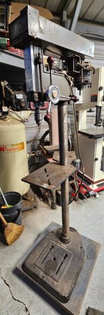
PSA: Check your feed stop bracket
About a year after I completed the refurb on my keeper machine, dp#15, I discovered that the feed stop bracket had started sliding down the quill. Shortly after that, I swapped out the quill with one that had the snap ring.
If its been a while since you refurbished your early Craftsman 100, it may be time to check your feed stop bracket to verify that it's still fully seated. A fully seated bracket should be about 3/32" below the bottom edge of the quill.

There are several clues that will help identify an out-of-position bracket.
Your bracket may be sliding off the quill if:
- you can see the pulley lift up at the end of a feed return
- you can hear the spindle collar bumping up against the spindle pulley shaft on a feed return
- you can feel the spindle collar bumping up against the spindle pulley shaft on a feed return
- you cannot see the entire thrust collar below the bracket

- you can see too much spindle sticking up above the pulley

The bracket on one of my recent machines was badly worn when it made contact with the chuck collar.

Check
this post for the consequences of the feed stop bracket sliding off the quill.
I now normally use a green bearing retainer on feed stop brackets/quills when assembling these drill presses.

.

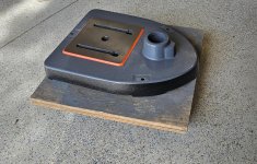
 They are spacers to make room for the pillow-block bearings.