To avoid these ads, REGISTER NOW!

Dream Lathe: 1943 Sidney

ClappedOutBport

Well-known member
Joined
Mar 30, 2016
Messages
998
Disaster Lathe: 1943 Sidney

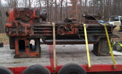
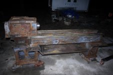
Well after seeing 86turbodsl getting his awesome American Pacemaker (and me wanting a lathe of that quality for a long time), I just couldn't take it anymore and dad and I picked up this 1943 Sidney 16x54. This lathe is of about the same quality and design as a Monarch. Built in the same town, and designed by the same guy, so I've been told.

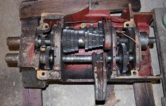
It swings 18.5 inches and has somewhere around 54" between centers. The tailstock is an MT4 and the head stock is a D1-6. It has 16 speeds and the headstock is jam-packed full of these beautiful herringbone gears. Some more info here. http://www.lathes.co.uk/sidney/

I inspected it under power, though I didn't do a hugely wonderful job inspecting it, I forgot to look at a lot of things. It's got busted up handles, the feed clutches don't hold, the cross slide leadscrew bracket is busted and there is quite a knocking from the QCGB at higher speeds. It's got a decent amount of wear and damage, but I'm confident we will be making good parts before spring.

I know you guys aren't as interested in videos as I am from my last restoration so I'll try post more photos.

attachment.php
 

Attachments

  • sidney.jpg
    sidney.jpg
    142.2 KB · Views: 1,972
Last edited:
To avoid these ads, REGISTER NOW!
OP
C

ClappedOutBport

Well-known member
Joined
Mar 30, 2016
Messages
998
Day Zero:

The lathe was about 150 miles away, but the seller had it totally ready to go and already rigged when we got there. He had it between a two post car lift with two arms under the headstock casting in the access panel holes, one arm under the chip pan, and the other pulling on a chain rapped under the chip pan. I know you aren't supposed to lift by that, but thankfully these old lathes aren't Chinese pot metal and it didn't bend at all. He had about 30 feet in front of his shop door, and the truck and trailer were about 40 ft long, but I got super lucky and backed it right under first try. From the initial lift to setting down on the trailer was 15 minutes, tops. That was pretty awesome, lifting these can be stressful. Dad's poor dying Isuzu NPR is very short on power for such a journey, I was flat out for a considerable portion of the journey, but we made it home with no issues.
 
OP
C

ClappedOutBport

Well-known member
Joined
Mar 30, 2016
Messages
998
Day One:

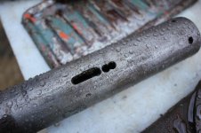
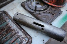
Dad started off with the pressure washer and removing weight (and things that need work) while I started prepping the unloading area. The more we dug the more damage we found. Nothing to cause any regrets yet, but it will certainly need some work. The pressure washer reveled a large crack in tailstock housing where the spindle is. It's all the way deep (about 5/8") and 3-4" long. That will be tig or gas brazed. The wingies on the cross slide bracket will be cut off and new steel ones brazed on. The tailstock spindle has been butchered with a drill. Someone made their own ejection slot and drilled some other holes for good measure. I hope the taper is ok. The included 12" 4 jaw is entirely clapped out. It might function but I don't know how well. Jaws are very wiggly. Dad had a fantastic identical replacement a few years ago, but sold it as we didn't have a machine for it. Oh well, there are more out there.

Lots of machine work too. The bushings for the carriage rods will need to be remade. Same for the leadscrew bushings. Tailstock nut is missing half it's threads, so there is another thing to do. It did not come with a motor, and the original motor pulley is something like 1 3/8 with a very well made (almost invisible) reducer down to some ******* size. I will need to press it out and make a new one. I guess it's finally time to get some keyway broaches and make my new keyways. Dad just got a 5 ton Dake arbor press so that should go well.

The original motor was an 1140 RPM 3 phase Westinghouse, we will be replacing it with a period correct 5hp 1750RPM repulsion-induction single-phase motor as that is what we have on hand. That will give us a nice little speed increase up to around 830 RPM in high gear.

This was originally supposed to be just a refubish, but now it looks like we will be working on everything but the motor, and paiting is as well since there is almost nothing left. So I'll call this a simi-restoration.

No new photos yet as the light was very low today, but I promise there will be some to come. :)
 

DocsMachine

Well-known member
Joined
Sep 16, 2006
Messages
1,869
The pressure washer reveled a large crack in tailstock housing where the spindle is. It's all the way deep (about 5/8") and 3-4" long. That will be tig or gas brazed.

-Try Muggy Weld. It's a stick-weld rod that is designed to work specifically on cast iron, and if your iron is clean, it "butters" on almost as well as 6011 does on mild steel. On many pieces, I never even bothered with pre or post heat- inlike high nickel rod, this stuff is slightly softer than the surrounding iron, and like brass/braze, will deform to take up any distortion.

The bushings for the carriage rods will need to be remade.

-That is a very interesting uppermost rod. Kind sticking out in the breeze, as far as a general wear-and-tear placement goes. I assume that's the leadscrew reverse rod, or something similar- I have a similar one on my Springfield, except it's second from the bottom, above the clutch rod.

That will give us a nice little speed increase up to around 830 RPM in high gear.

-I assume it has pressurized lube? Or is it just splash oiled? If it's just splash oiled, you might want to watch out for that, you could theoretically overspeed the bearings a bit- at least, run them faster than they can be oiled.

That would mainly be a worry for the input shaft, of course, since you may not be running it at top speed all the time. I've been kind of worrying about that myself, as my lathe originally came with an 1140, too, and was replaced long before I got it with a more modern 1725. That bumps my top speed up to a whopping 900, and I do have pressurized lube, but I do NOT want to have to dismantle the head and replace any of those giant bearings. :D

This was originally supposed to be just a refubish, but now it looks like we will be working on everything but the motor, and painting is as well since there is almost nothing left. So I'll call this a semi-restoration.

-It's actually fairly easy if you just break it down into subassemblies. I dismantled mine pretty much completely (I didn't break down the headstock) and simply cleaned, repaired and painted each part as I put it back on.

Doc.
 
OP
C

ClappedOutBport

Well-known member
Joined
Mar 30, 2016
Messages
998
-Try Muggy Weld. It's a stick-weld rod that is designed to work specifically on cast iron, and if your iron is clean, it "butters" on almost as well as 6011 does on mild steel. On many pieces, I never even bothered with pre or post heat- inlike high nickel rod, this stuff is slightly softer than the surrounding iron, and like brass/braze, will deform to take up any distortion.


-That is a very interesting uppermost rod. Kind sticking out in the breeze, as far as a general wear-and-tear placement goes. I assume that's the leadscrew reverse rod, or something similar- I have a similar one on my Springfield, except it's second from the bottom, above the clutch rod.


-I assume it has pressurized lube? Or is it just splash oiled? If it's just splash oiled, you might want to watch out for that, you could theoretically overspeed the bearings a bit- at least, run them faster than they can be oiled.

That would mainly be a worry for the input shaft, of course, since you may not be running it at top speed all the time. I've been kind of worrying about that myself, as my lathe originally came with an 1140, too, and was replaced long before I got it with a more modern 1725. That bumps my top speed up to a whopping 900, and I do have pressurized lube, but I do NOT want to have to dismantle the head and replace any of those giant bearings. :D


-It's actually fairly easy if you just break it down into subassemblies. I dismantled mine pretty much completely (I didn't break down the headstock) and simply cleaned, repaired and painted each part as I put it back on.

Doc.

Unlikely. I am very much not a fan of welding cast iron even with the fancy magic rods. Some people swear by them, I swear at them.

Yes, leadscrew reverse. Somehow mostly undamaged.

It has a pump and sprays or at least dribbles oil out. I assume the bearings get at least positive flow, though I don't know if it is under pressure. They are tapered rollers, 830 RPM ought to be fine. Especially since the factory high speed version did 1000. :)

We've already removed a lot of components. The issues is that the shop is way too small for this thing and once it's shoehorned against the wall there will be no getting the motor in or out, no painting on the rear or sides, etc. So a lot will have to be done outside.
 
Last edited:

Earp69

Well-known member
Joined
Sep 20, 2016
Messages
859
What do you figure that sucker weighs and how did you get her unloaded? Looks like a good project and a nice machine once you get it all back together
 

DocsMachine

Well-known member
Joined
Sep 16, 2006
Messages
1,869
Unlikely. I am very much not a fan of welding cast iron even with the fancy magic rods. Some people swear by them, I swear at them.

-I understand. But these might be worth a closer look. They're not on the same level as those snake-oil "solder aluminum" things you get at the state fairs. I've used Muggy to fix my 1909 'camelback' drill, my Arboga gearhead drill, the base casting of the Springfield (which had previously been welded with what appeared to be 6011) both the QCGB levers on the same machine, and about a dozen smaller bits like handwheels, bases and exhaust manifolds.

Yes, leadscrew reverse. Somehow mostly undamaged.

-Interesting that you got both LSR and a threading dial. When I was researching mine, I was given to understand that a lot of similar vintage machines with that feature didn't include a dial, since the LSR made it basically irrelevant.

(That said, I'm used to threading with a dial, and have been looking to either find one that fits, or maybe even make one. Best of both worlds, and all that. :D )

It has a pump and sprays or at least dribbles oil out.

-Mine has external piping, since the 'sump' is separate from the head, in the base casting. When I got it, it had a long chunk of badly installed soft copper line, that had been badly bashed in places. Luckily, it still flowed at least some oil, but replacing the old line with never, better stuff turned it from a dribbler to a gusher.

Of course, the pump is run off the input countershaft, which, as noted, is being run 30% faster than usual.

Look for a filter or a strainer or even a check valve, and see if it's dirty or clogged. (And of course flush out the old and put new in at some point during the rebuild. :D )

What do you figure that sucker weighs[?]

-My Springfield is close to the same size (16" x 56", actual swing about 18") and might only be a little beefier, and we figure it weighs between 5,500 and 6,000 lb.

Doc.
 
OP
C

ClappedOutBport

Well-known member
Joined
Mar 30, 2016
Messages
998
-I understand. But these might be worth a closer look. They're not on the same level as those snake-oil "solder aluminum" things you get at the state fairs. I've used Muggy to fix my 1909 'camelback' drill, my Arboga gearhead drill, the base casting of the Springfield (which had previously been welded with what appeared to be 6011) both the QCGB levers on the same machine, and about a dozen smaller bits like handwheels, bases and exhaust manifolds.

I hear ya Doc. I appreciate you bringing in some experience and giving a recommendation. But here is the issue. Dad is chief financial officer of this and all projects as I am a college student with negative money. I already spend plenty of his money (so he tells me). Trying to convince the old man buy $160 a lb welding rods that I don't believe in myself will be neigh impossible. I'd need the whole 1/2 lb just to practice and get the tailstock welded. Or, I can use the silicon bronze I familiar with, is $12 a lb, it almost certainly won't crack, it adheres very well, and is at least as strong as the cast. The choice seems pretty clear to me. I'd love to try that stuff someday, but unless the alloying elements in it are very expensive, I think they are charging criminal amounts for the stuff.

-Interesting that you got both LSR and a threading dial. When I was researching mine, I was given to understand that a lot of similar vintage machines with that feature didn't include a dial, since the LSR made it basically irrelevant.

This is a very nice operators lathe. It may not be as beefy as a pacemaker or you springfield but the controls are excellent. Definitely a good lathe to run 10 hours a day.

Look for a filter or a strainer or even a check valve, and see if it's dirty or clogged. (And of course flush out the old and put new in at some point during the rebuild. :D )

The guy showed us the strainer before we left. He said it was leaking and gooped it with silicon. We will most likely remove it and gasket it.

What do you figure that sucker weighs and how did you get her unloaded?

Book weight is around 4700lbs. We have not unloaded it yet, we are still preparing things. That will be the most treacherous part, and hopefully we won't end up with a parts lathe over on its side. All our previous machines were under 2500lbs and so our backhoe could lift them. Now we've gone over, and significantly so. We've got some plans, we'll get creative, take it slow and I think all will go well.
 

86turbodsl

Well-known member
Joined
Jul 1, 2005
Messages
6,558
Location
Michigan
Subscribed. Looking forward to this one. I have tig brazed and like it, but I think you would need a really big tig for that crack. Muggy weld you could get away with a smaller welder.

Sent from my LG-TP450 using Tapatalk
 

rsanter

Well-known member
Joined
Dec 22, 2007
Messages
18,521
Location
visalia ca
Stay with the 3ph motor and get a VFD
It’s a better setup and gives you RPM adjustment between the gears
 
OP
C

ClappedOutBport

Well-known member
Joined
Mar 30, 2016
Messages
998
Subscribed. Looking forward to this one. I have tig brazed and like it, but I think you would need a really big tig for that crack. Muggy weld you could get away with a smaller welder.

Sent from my LG-TP450 using Tapatalk

330A/BP with a water cooled torch ought to laugh at it.

Stay with the 3ph motor and get a VFD
It’s a better setup and gives you RPM adjustment between the gears

You offering? :p That was the plan, but it's not in the budget. It has 16 speeds, that's plenty for me.
 

DocsMachine

Well-known member
Joined
Sep 16, 2006
Messages
1,869
Stay with the 3ph motor and get a VFD
It’s a better setup and gives you RPM adjustment between the gears

-While I agree with this, the bigger VFDs can get pretty expensive. He didn't say how big the existing 1140 RPM motor is, but my Springfield came with a 10HP, and a VFD for something that size cost me over $1,200, and another couple hundred in shipping- it weighs close to 80 lb.

Personally, yes, I'd spring for a VFD if for no other reason than the "soft start", but even a 5HP one is going to cost quite a bit.

I would recommend not getting rid of the original motor, though, it can always be reinstalled later, as needs and funds allow.

Doc.
 
OP
C

ClappedOutBport

Well-known member
Joined
Mar 30, 2016
Messages
998
No motor. The PO removed the 3 phase it came with and installed a single phase which he kept. Original was a 5hp westinghouse 1140, though the gears and clutch are very beefy and could probably handle much more. We have a "5hp" chinese vfd that could be installed, but only 3450 rpm 5 horse 3 phase motors or a 3hp 1750. Single phase is fine on a clutch lathe.
 

86turbodsl

Well-known member
Joined
Jul 1, 2005
Messages
6,558
Location
Michigan
You can make any change you need with pullies. I'd be on an rpc at that power level. Mines 7.5 and it's probably a bit underpowered. I'd want no less on a 16in lathe. Low rpm means higher torque. Original 1140 7.5 means the torque of a 10hp. I'd do a 20hp rpc and a 10hp 3ph motor. I got my 20hp weg brand new at an auction for 38 bucks. Don't know where your at, but hgr in Cleveland has big motors fairly cheap. Or I can keep an eye out for you. 3ph motors are cheap if bought right.

Sent from my LG-TP450 using Tapatalk
 

DocsMachine

Well-known member
Joined
Sep 16, 2006
Messages
1,869
No motor. The PO removed the 3 phase it came with and installed a single phase which he kept.

-Ah. Then definitely, go with what you have. :D

I would, however, keep in mind the idea of an eventual conversion to 3-phase, with or without a VFD. They're smoother, you get more torque, etc. And at least on my smaller lathes, I love the ability to dial a speed up or down to help eliminate chatter.

Original was a 5hp westinghouse 1140, though the gears and clutch are very beefy and could probably handle much more.

-As noted, my Springfield, which I suspect is built similarly, has a 10HP, although I have to admit I don't have any idea what it was stock. I suspect about the same. Similarly sized Pacemakers can have 10HP to 20HP. The big 17x56 Colchesters (80s models) that my local college had, were 7.5HP.

But the thing is, you and I- and most people here- aren't going to be making cuts where we measure chip removal in pounds per hour. :D I toyed with the idea of switching my 10HP over to a 5HP I had- not only to save on day-to-day electrical costs, but it'd drop the cost of the VFD I needed from $1,200 to something like $600.

And I suspect that in low gear (like 80 RPM) I'd still have more power than I knew what to do with- like making 1/2" deep cuts in mild steel at 10 thou a rev. :D

I may still, have have a selection of 3HP and a couple 5HP 3-phase motors.

You can make any change you need with pullies.

-Not necessarily. To slow down a faster motor to produce the same input shaft speed, you need to make the motor pulley smaller or the input pulley bigger.

The input pulley on mine is nearly a foot in diameter and a solid six-plus inches deep. Finding a replacement would be difficult at best, and making one would cost several hundred just in the block of material you'd need to turn one.

It'd be a lot easier to make the motor pulley, but most on lathes this size are already fairly small- only about 4" to 5" OD. Making a smaller one would be relatively easy, except there's a limit to how tight a radius you can make the belts turn. Try and make 'em bend too 'sharp' around too small a pulley, and they start to wear out a lot faster.

Doc.
 
OP
C

ClappedOutBport

Well-known member
Joined
Mar 30, 2016
Messages
998
-Ah. Then definitely, go with what you have. :D

-As noted, my Springfield, which I suspect is built similarly, has a 10HP, although I have to admit I don't have any idea what it was stock. I suspect about the same. Similarly sized Pacemakers can have 10HP to 20HP. The big 17x56 Colchesters (80s models) that my local college had, were 7.5HP.

The book says it can have a 5HP or 7.5HP. Since a 1750 RPM 10HP makes no more torque than an 1140 RPM 7.5, I'm sure this one could run 10. And I'd do it if I had it.

But the thing is, you and I- and most people here- aren't going to be making cuts where we measure chip removal in pounds per hour.

Speak for yourself Doc! I tend to push machines to their limits in very short order. The main reason I wanted this machine is that it takes very long to machine anything of any reasonable size on our 1hp 10x36. I am sure I'll have used up all 5hp within a few weeks of getting it operational, assuming I can afford to feed it stock that big.

The input pulley on mine is nearly a foot in diameter and a solid six-plus inches deep. Finding a replacement would be difficult at best, and making one would cost several hundred just in the block of material you'd need to turn one.

Dad and I had a bit of a squabble over that today. He is extremely resistant to making any new parts, even if trying to fix the old ones would take more time. I'd like to use the original or a slightly larger pulley. The original is factory sleeved to 1 1/4. It would need a second sleeve to get down to 1 1/8" for the motor. He suggested making a double adapter out of pipe (!!! no way José. I don't turn pipe). Not only would it then double adapted, but then it needs a custom stepped key. I was just going to make a new sleeve out of some 2.5" stock I brought home. He is very protective of it though, which is why I guess this lathe won't see a lot of use until I can afford to feed it the appropriate material it wants. He also has a 1/2" smaller 2 belt pulley. It's rusty and I would really like to use the original if I can. What is the point in having a lathe, bridgeport, arbor press, etc if we are not going to use them?

He started in on the threading dial (why there of all places?) and it's all buggered up. The shaft was somewhat bent before, but is more bent now. I told him just to stop messing with it, I'll just build a new one when we near completion.

Anyway, We'll figure it out and meet somewhere in the middle. For now, here are pictures of the carnage.

attachment.php


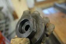
The thread dial housing was snapped. Like, how do you even do that?

attachment.php


Tailstock tail piece is busted.

attachment.php


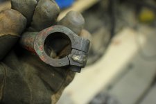
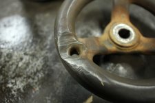
One of many broken handles.

Note the second break was not at the braze joint.

attachment.php


attachment.php


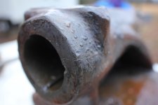
More whyyyy? I didn't wind the ram far enough out to see this as it went very freely.
 

Attachments

  • image_6193.jpg
    image_6193.jpg
    96.1 KB · Views: 1,601
  • image_6194.jpg
    image_6194.jpg
    108.9 KB · Views: 1,595
  • image_6195.jpg
    image_6195.jpg
    127.7 KB · Views: 1,598
  • image_6196.jpg
    image_6196.jpg
    98.5 KB · Views: 1,591
  • image_6197.jpg
    image_6197.jpg
    110.9 KB · Views: 1,592
OP
C

ClappedOutBport

Well-known member
Joined
Mar 30, 2016
Messages
998
attachment.php


Forgot to open up my aperture outside. Sorry. The weather has taken a turn for the worse and it was sleeting the whole time taking these photos so I tried to limit the water getting on my camera.

attachment.php


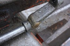
Jesus. What is with these guys and playing whack a mole on the handles. The one in the background isn't broken but it is wallowed out and needs boring and new parts.

attachment.php


attachment.php


They didn't get them all, but most. At least the carriage handwheels are all straight. I see those often bent from droppage, whacking with a forklift, etc.
attachment.php


These ears will be cut off and have steel brazed in place. That was noticeable even from the facebook photos so I expected this repair.

-------------------

I got the forks on the backhoe to move some stuff out of the way for the unloading. Alabama is getting some unusual weather, it snowed today and the ground is a bit slick to back it into place. We have to use one of the tractors and not the truck to get it backed into place as it's a pretty sharp turn. Maybe tomorrow or thursday we will throw the hoist at it.
 

Attachments

  • image_6204.jpg
    image_6204.jpg
    117.1 KB · Views: 1,595
  • image_6203.jpg
    image_6203.jpg
    120.9 KB · Views: 1,591
  • image_6202.jpg
    image_6202.jpg
    105.1 KB · Views: 1,591
  • image_6200.jpg
    image_6200.jpg
    108.3 KB · Views: 1,590
  • image_6198.jpg
    image_6198.jpg
    93.9 KB · Views: 1,592

DocsMachine

Well-known member
Joined
Sep 16, 2006
Messages
1,869
What's that bracket with the two broken feet go to? How'd it break? (I mean, in use/ a crash, or external damage.)

And on the clutch lever, my clutch controls were broken and had been repaired in a couple of places. Rather than fixing them again, I'm planning on rebuilding my parts in steel, welded and shaped to look like cast.

Because I'm not sure I trust the cast anymore, nor the repairs- on mine the clutch not only disengages the headstock drive, but also engages the brake. (Built into the clutch.) I do NOT want some part of that linkage breaking and having to dive for the VFD off switch- the clutch/brake works nearly instantaneously, the VFD will have a couple seconds of "ramp down", and this is way too powerful a machine to risk a crash.

Speak for yourself Doc! I tend to push machines to their limits in very short order.

-Even just 5HP with that much gear reduction produces a LOT of power. What you'll find out in short order is where the weak link in your system is. :D

Mine had four broken gears in total, in the QCGB- two had sheared keys. On mine, there used to be a pin that drove the leadscrew- apparently the ham-handed types broke that often enough they actually machined it for a woodruff key. Well, the pin is supposed to be soft, and is designed to shear, specifically to save the more expensive and harder to replace parts.

Well, once they put the woodruff in there, I'm sure that was when they started breaking the gears in the QCGB.

I'm not saying to baby the machine- far from it. Just don't expect to be able to dive in there and peel a half an inch off of alloy steel at a pass. It can be done, but only with the right setup, and with a lot of care and attention- otherwise, it's a good way to break a tool, crack a compound or shear a key somewhere.

It's also worth keeping in mind that machines of this class don't take prisoners. If you're not paying attention, it'll be more than happy to winch you in and turn you to putty.

The main reason I wanted this machine is that it takes very long to machine anything of any reasonable size on our 1hp 10x36.

-Ditto. The summer I bought mine, I'd had three jobs making an aluminum adapter plate 1-1/2" thick and 10" square. My Logan is a 2HP with a 3-phase motor, but out at the periphery I could only take 40-50 thou at a pass- and I had to go over an inch deep, in a depression some 9" in diameter.

It took a long, long time- and of course it was a rush job, too. :D

Had I had the Springfield up and running at the time, I could have finished them in maybe two hours, rather than almost eight. ('Course, since then I've only had maybe three more jobs that were big enough to need a machine this size, but hey... :D )

Doc.
 
To avoid these ads, REGISTER NOW!
OP
C

ClappedOutBport

Well-known member
Joined
Mar 30, 2016
Messages
998
Damn. Wrote a huge long post and it disappeared. Ok. Rounds two.

What's that bracket with the two broken feet go to? How'd it break? (I mean, in use/ a crash, or external damage.)

That is the cross-slide leadscrew bracket. Thurst bearing forward and back, bronze bushing in the middle.I'm guessing that they crashed the lathe hard and the tremendous force shoved the cross slide screw backwards breaking the braket.

Because I'm not sure I trust the cast anymore, nor the repairs- on mine the clutch not only disengages the headstock drive, but also engages the brake. (Built into the clutch.) I do NOT want some part of that linkage breaking and having to dive for the VFD off switch- the clutch/brake works nearly instantaneously, the VFD will have a couple seconds of "ramp down", and this is way too powerful a machine to risk a crash.

Same here on the clutch and brake system. The one broken part of the linkage is well repaired, no worries there.

Pix of the gears pls

Will do, when we remove the cover to make a gasket for it.

Lets see, day 4 is it?

The day started with some little jobs, one of them being removing ruined ball oiler gits. These have hollow, soft balls, I suppose so you can remove them. I screwed a screw into them and was hoping to pull them out with a slide hammer, but dad had no such appropriate version. After trying a few things with no luck, I hopped on the lathe and made my own version of a vise-grip slide hammer I'd seen on youtube. I single pointed the 7/16-14 thread on the lathe because I hate dies and why not right? I can't believe I didn't make this years ago. 30 minutes to make the tool, 10 seconds to remove the git.

attachment.php


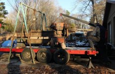
The the ball really started rolling, we got the hydraulic pressed move out of the way (and the rain) cleaned off the outdoor pad, hooked up the kubota to the trailer, and got it backed into place. The 7000lb(?) trailer was a bit more than the 2000lb(?) kubota wanted to deal with, though we got it there in the end. I was supposed to reinforce the low-strength, bubblegum-welded gantry before we lifted it off, but hell, the ball was rolling, so on we went. All of our previous machines were under 2500lbs so the backhoe could lift them, but this time we went over, and way over. So we had to get a bit creative. But, it all worked out.

If you get squeamish by very iffy rigging on rare boat anchors, now is your last chance to look away.

attachment.php

attachment.php


I will follow that image up by saying that I have never dropped a machine. Though the safety factor here was maybe 1.1. Don't try this at home, eh? The engine hoist is a bit beefier than you may think, it's rated for 4 tons at no extension and less at full. They is no marked limit, and it may have had more than 1 ton on it, going by the harbor freight 4-1 de-rating at full extension, so it may have still been overloaded. The plumbing pipe gantry had a noticeable bend in the top bar, but it too held. We didn't move it all the way off the trailer like that, we just picked it up 2 inches, move it to the end, then shortened up the engine hoist. So it was less sketchy setting it down. I'll have a video put together when I get enough content.
 

Attachments

  • IMG_7030S.jpg
    IMG_7030S.jpg
    136 KB · Views: 683
  • IMG_7027S.jpg
    IMG_7027S.jpg
    134.2 KB · Views: 676
  • IMG_7032S.jpg
    IMG_7032S.jpg
    77.3 KB · Views: 673
OP
C

ClappedOutBport

Well-known member
Joined
Mar 30, 2016
Messages
998
Day 5

Dad stripped paint today. Almost all of the orange and green is gone, it is primarily a grey machine now. I only put in a late half day so no new pictures of the machine. I started work on the top half of the cross slide and the tailstock and at least I don't have bad news to report. The cross-slide is pretty un-abused, only some wear and a tiny amount of damage.

Here is the threading stop so you can re-zero with quickly without looking when threading. I don't totally understand how this part works yet. It seems like there must be some way to engage and disengage it but I don't see it yet. There is normally a ball bearing that rides in the groove, but none such was in there. It seems like the old ball got a flat spot in it, then got drug around the housing for a ride leaving a groove. It's not idea but I don't think it's enough to cause any issue. That's the only damage on the upper half of the cross slide. Otherwise it's just worn, but not too badly. There is no scraping for flaking marks to be found anywhere on the machine. I don't know if these were these scraped/flaked. If it was, it must have spent some time outside as there is nothing even on the very extremes of the ways.

attachment.php


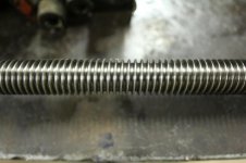
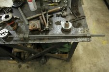
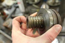
The cross slide screw is worn. About 20 thousands of backlash in the middle, ends are tight. The screw is shiny and polished with little to no scratching. The cast iron nut however must have been packed with chips many times and the threads are fairly torn up. Still serviceable though if need be. The end of the screw is worn and pitted. There is a pinned on collar that is loose that should be a press fit. It did press off, telling me the seat is worn. Also on the end is an extremely ******* 0.460-32 thread for the bearing preload. It's crusty too.

attachment.php

attachment.php

attachment.php

attachment.php
 

Attachments

  • IMG_7045S.jpg
    IMG_7045S.jpg
    74 KB · Views: 622
  • IMG_7044S.jpg
    IMG_7044S.jpg
    71.7 KB · Views: 622
  • IMG_7046S.jpg
    IMG_7046S.jpg
    115.3 KB · Views: 631
  • IMG_7049S.jpg
    IMG_7049S.jpg
    67.9 KB · Views: 627
  • IMG_7043S.jpg
    IMG_7043S.jpg
    71.6 KB · Views: 625

2mJps

Well-known member
Joined
Feb 20, 2012
Messages
1,797
Location
north central Mo
I dont know were you live but i have a lathe i would have sold cheap.I unloaded it buy jacking the front of the trailer up till the rear was on the ground and sild it off.I got a chance at a shorter lathe so i need to sell one.
 

ZRX61

Well-known member
Joined
Aug 15, 2006
Messages
28,716
Location
Solar Blight Valley, SoCal
They made some fairly big lathes. Shop in Burbank has one with about a 30in swing & a 20ft bed. Tailstock was about 3ft long. I have some pics if it someplace.
 

dutchgray

Well-known member
Joined
Sep 28, 2014
Messages
6,468
Location
Dorset. England.
I dont know were you live but i have a lathe i would have sold cheap.I unloaded it buy jacking the front of the trailer up till the rear was on the ground and sild it off.I got a chance at a shorter lathe so i need to sell one.

Where I live a big old lathe like these that needs work will often go for scrap money, there isn't much demand for big old lathes beyond a few makers, I looked at a Wilson 17" by 36" while I was picking up my horizontal bandsaw which would have been made just after WW2 and was complete with 3 and 4 jaw chucks, 2 faceplates and a steady, how worn out it was or if It had anything broken I don't know, but there was nothing obvious, didn't sell at £200 on Ebay.
 

86turbodsl

Well-known member
Joined
Jul 1, 2005
Messages
6,558
Location
Michigan
Most people don't have the knowledge or capability of moving something that weighs what a large lathe does. That's why the small lathes are $$$.

Sent from my LG-TP450 using Tapatalk
 
OP
C

ClappedOutBport

Well-known member
Joined
Mar 30, 2016
Messages
998
I dont know were you live but i have a lathe i would have sold cheap.I unloaded it buy jacking the front of the trailer up till the rear was on the ground and sild it off.I got a chance at a shorter lathe so i need to sell one.

Well thanks but:
A.) Little late now,
B.) We are no where close
C.) We were looking for a very specific type of lathe, not just any old lathe. We have a 10x36 currently. We wanted something with: a swing between 15 and 19 inches, at least 40" between centers, less than 11' long, roller bearing headstock, gear head, clutch type preferably, and very heavily built. The lathes I can think of that fit that bill are Monarch, Lodge and Shiply, American Turn Works, Axleson, and Sidney. Of those, only two have headstocks devoid of spur gears, the Sidney and Monarch. We've had our eyes peeled for about 4 years now. If we could have removed the size and location limitations, I'm sure we'd have stuffed this beauty in a few years ago. https://www.govdeals.com/index.cfm?fa=Main.Item&itemid=22&acctid=10864

-------------------

Not much news fit to print. Dad and I have been struggling with the tapered pins. They are tight! We've had to drill a few already, and our drilling wasn't quite perfect. We'll probably borrow some reamers and clock them 90 degrees or a move them over a little where we have that luxury.

I've been working on the busted headstock handles a bit, prepping the new pieces where they were broken off. We are going to try to get everything ready for brazing marathon and get it all done in one day.

Dad has been paint stripping. He is almost down to bare cast. Looks like the machine has been painted 4 times. The factory blue-grey, gray, orange, and green, in that order. Just a little of the gray and blue remaining which is stuck pretty well. I've been cleaning the parts we've removed, lots of hours at the safety clean and wire wheel. The tailstock casting is worn about 11 thousands in the front where it meets the ways and maybe 5 or so in the rear. I figure we'll jack it up in the middle with some brass shim stock, no harm there. The compound is in pretty good shape, no damage to it other than a 2-3 crash marks. Cross slide seems fine as well other than the damage mentioned.

I also removed the motor plate and have started on the clutch. The clutch uses what feels like a phenolic friction surface. What an amazing feeling material. I wish modern plastics were half that good. The motor plate is ridiculous. A reasonable motor plate in peace time would be something like 1/4" steel plate with reinforcement ribs. That would be even more reasonable in war time where materials were scarce. What did Sidney use? 1" solid cast. Machined flat. Super heavy.

I've got a lead on a 10hp 3 phase motor with what looks like an 8" pulley on it for a good price. I doubt the seller will respond though. What is with people and doing that these days???

attachment.php
 

Attachments

  • IMG_7052S.jpg
    IMG_7052S.jpg
    150 KB · Views: 568

DocsMachine

Well-known member
Joined
Sep 16, 2006
Messages
1,869
Dad and I have been struggling with the tapered pins. They are tight! We've had to drill a few already, and our drilling wasn't quite perfect. We'll probably borrow some reamers and clock them 90 degrees or a move them over a little where we have that luxury.

-Yeah, those things can be buggers. Keep in mind they're taper pins, so if your drill goes a little off, you can ream the taper deeper, or step up to the next size pin.

Also, when replacing them, make sure you get soft pins, not hardened. In a lot of cases back in the day, a pinned shaft used the pin itself as the "fuse"- it would shear to save the shaft, gears or other, more expensive or more difficult to replace parts.

I've got a lead on a 10hp 3 phase motor with what looks like an 8" pulley on it for a good price.

-Did you say you had the original pulley? If not, it's worth noting that the original was probably something like 4" in diameter. An 8" pulley would give you, what, something like four times the belt speed? Not sure that badboy would like a top spindle speed of something like 3,000 RPM. :D

Not for long, anyway. :)

How many belts does it use? Mine originally had I think six, but came with five, or something like that.

Doc.
 

86turbodsl

Well-known member
Joined
Jul 1, 2005
Messages
6,558
Location
Michigan
You have made some fast progress on that lathe, and it looks good! Not sure where you are, but 10HP motors are fairly common around here. I can send them your way if you wish?
 
OP
C

ClappedOutBport

Well-known member
Joined
Mar 30, 2016
Messages
998
Did you say you had the original pulley? If not, it's worth noting that the original was probably something like 4" in diameter. An 8" pulley would give you, what, something like four times the belt speed? Not sure that badboy would like a top spindle speed of something like 3,000 RPM. :D

Yes we have the original pulley. I'm no dummy doc. :bounce: I've done the math. The original pulley was 6" with an 1140RPM motor and a high gear of 562 RPM. With an 8" and a 1750, that comes out to around 1150 RPM, or 15% more than the optional high range speed they sold from the factory.
How many belts does it use? Mine originally had I think six, but came with five, or something like that.

Jesus, the more I hear about your Springfield the more this Sidney sounds anemic. The original pulley had "only" 4 v-belts.

You have made some fast progress on that lathe, and it looks good! Not sure where you are, but 10HP motors are fairly common around here. I can send them your way if you wish?

We have no were inside to work on it and we don't want it out in the rain for any longer than possible. Dad is retired and I'm a college student off on break, so we've been busting our butts to get it inside.

That would be awesome, but being down in Alabama shipping would be killer, even if the motor was free. The one on FB that is gone now was under 100 miles away and I was more interested in the pulley than anything else. It was $40, so I guess they aren't too bad around here when you can find them. The original 6" has a factory bushing, changing the size from 1 3/8 down to some weird size, and I don't have the broaches to make a new one. You need special broaches to be able to broach that length, most are only good for maybe 2". And I wouldn't have minded the speed increase from the larger pulley.
 

86turbodsl

Well-known member
Joined
Jul 1, 2005
Messages
6,558
Location
Michigan
Bah, shipping not problem. If you aren't on owwm.org yet, get signed up and on there. Lots of us running all over the country with other people's loads. It's called ruckering and ive hauled other people's stuff 600miles before. There's a subforum there for it.

Sent from my LG-TP450 using Tapatalk
 

2mJps

Well-known member
Joined
Feb 20, 2012
Messages
1,797
Location
north central Mo
My lathe had alot of coats of paint on it. I wanted to remove its paint we sold the shop and i didnt have any place to store it so it had to seat out side. I coated it with STP then cover it up. The first years i uncovered it and oiled it agin. After 4 years i uncovered it to put it in a shop. The paint was peeling off down to the bare castings . I cleaned it up and started useing it agin but never painted it.
 
OP
C

ClappedOutBport

Well-known member
Joined
Mar 30, 2016
Messages
998
Bah, shipping not problem. If you aren't on owwm.org yet, get signed up and on there. Lots of us running all over the country with other people's loads. It's called ruckering and ive hauled other people's stuff 600miles before. There's a subforum there for it.

Sent from my LG-TP450 using Tapatalk

I'll check it out, thanks.

-------------

Today was a ******* disaster. I should have quit while I was ahead. I'm gonna blame it on 86 because this sounds like a story he'd tell lmao.

So, to preface. A lot has been going on behind the scenes. I made the replacement part that was broken off for the two headstock handles a few days ago. I also made up new ears for the busted bracket. And ground out the tailstock crack. Today was supposed to be the day everything got brazed up. Kind of a production run, to speed things along.

Well everything fell apart quickly. First I set down a 7" grinder while it was spinning down and it slipped off the table. My ******* instintively tried to catch it as well. I slightly cut my hand, but I ruined the disk. Brand new one too. Second my harbor freight autodark's batteries died and my helmet randomly dimming and brightening mid weld isn't so great. Since I'm a gen Z I kind of grew up with autodarks and flip hoods aren't really my thing. But I don't give up that easily so I took out the Jackson, stripped and washed every component since it was opaque with dust and got back to work. Every lens dad had was too dark but I made do. It's a bit hard getting the tig arc started in the dark especially when your welder has weak HF. I got the bracket entirely brazed when the water cooler hose slipped off the barb. (Our fault, they were so tight we didn't think they warranted clamps. They did.) After fixing that, the water cooler motor wouldn't run. Sticky starting winding switch. Still have that to fix. After getting that going again, the pump started cavitation because the screen was clogged. Sheesh.

I got going again and got the handles brazed up. My braze was a bit blobby as the contamination and oxidation prevents it from sticking great right on the edges. Maybe I need more gas flow. I dunno. After I get one done, dad tells me he's gonna "reflow" it with the torch. I tried to express to him that its not gas brazing rod, there is no flux, and that if it was just that easy I'd have done it my self with the tig. He's determined so I go back to what I was doing. I check on him a minute later and nearly scream. He has the part glowing bright orange and a good section of my braze melted straight out of the joint. So I had to grind out the copious amounts of oxidation added in and blob even more braze back on. *Sigh* Maybe next time he'll trust me when I ask him to leave my hard work alone.

I called it quits there. I had enough. I was pretty mad at everything at this point and just wanted to go home. My car battery has been dying and I'd just been roll starting it while waiting on a check, but today it was too far gone. It would start and then just die and I ran out of hill. I could smell gas since the spark plugs weren't getting enough voltage I guess. So we got it pushed to the house and I got the battery charger out. I was rushing and didn't feel like dissembling the rube-goldberg of things blocking the extension cord, and I managed to drop a bike rack on mom's car. In my careless funk I also dropped a breaker bar on my car. Scratched 'em both. Nice going me.

Ok rant over, lets focus on the positives.

  1. The ruined bracket is brazed right! I'll have a post with more details, I was way too pissed to take any photos of my shoddy braze. Oh and Doc, I couldn't use muggy (at least I don't think) since I was attaching steel to cast. And I would have used at least $40 of rod. The silicon bronze is very strong btw. I made a small mistake, and forgot to run a root pass on one side before finishing the other. As a result I cracked my tacks and ear was pulled way off. I heated it a little and bent it back, but I cracked the joint in the process. The cast iron broke. Not the brass. And it took quite a lot of hammering to do so. I have no worries about the strength or the stress relief. (I preheated and postheated all parts.)
  2. The handles are repaired! They need some burr work, but these too will be strong and should last the rest of the machines life. I'll give a better post on these too.

I guess I'll get a good nights rest and hope tomorrow goes a bit better.
 
Last edited:

DocsMachine

Well-known member
Joined
Sep 16, 2006
Messages
1,869
I've had days like that. :D

I take that back, I've had months like that. :D

On the Muggy, I think it can do iron-to-steel, I seem to recall reading that somewhere, and when I was repairing both the base casting of the Springer, and one of the guide arms on my Wellsaw, I was going over prior repairs that were done with what I'm pretty sure was just 6011 rod. (And in the case of the saw arm, the repair was itself repaired at least once with plain MIG wire.)

I had no issues with incomplete fusion or contamination or anything, so I'm assuming the Muggy can stick iron to steel. I can't honestly say I've specifically tried it, but I think it can.

Sounds like you had the braze thing down pat, though. So no worries- as long as it's a good repair, who cares which method you use. :)

Doc.
 
OP
C

ClappedOutBport

Well-known member
Joined
Mar 30, 2016
Messages
998
Well, though dark fell as we did it, the lathe is on its skates now for rolling it indoors. We used the engine crane for the tailstock end as it was too narrow for the headstock, and the backhoe for the headstock end. Even with no motor, no clutch, no feedbox, no feed rods, and no carriage, the backhoe still wouldn't lift that end chained to the bucket, so we chained it a bit farther back and got it up. That tells you just how heavy this damn thing is, as the backhoe will lift a fully loaded Bridgeport with the bucket. I'm gonna have to recruit some friends to roll it in, there is way too much friction to get it to budge right now.

attachment.php


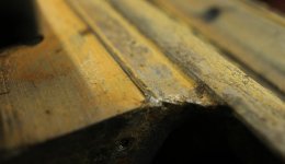
I finally got out the mic and measured the ridge in the saddle. I was conservative with my guess of 0.030". It's more like 0.046". A few more for the bed ways, and we're up over 0.050. Which makes a conversation I was having with Doc Nickle and 86turbodsl on 86's thread that much more relevant.

I asked:

Who cares if the carriage is dropped by 20 thousands?

In regards to replaceable ways on Pacemakers. Doc responded:

-The carriage does. The rods and shafts are fitted to the carriage at "ride height", for want of a better term. And what usually happens is the hardened ways don't wear as fast as the saddle, which is usually plain iron.

When the bed is ground, typically you also have to machine, grind or scrape the saddle to match the new ways, so between wear and removed metal, you're looking more like 50 thou or more.
And 86 replied:

Don't forget the carriage is driven off a rack on the underside of the front way so as you drop the carriage you are reducing tooth engagement and increasing backlash.

Well, what was a theoretical discussion a few weeks ago is a real one now. The feed rods don't seem to mind the bit of bend but I'm sure the rack engagement is pretty poor. I wouldn't worry about it too much except I'd like to take pretty heavy cuts since this will be a roughing lathe only after all. The rack could be shimmed down, but the cheapest material I can find would be $30 and I'd have to redrill the mounting holes so I don't know if I'll mess with it at all.

attachment.php


I also removed the feed box. This alone must be 250 lbs. It seems to be in "ok" shape except the tumbler is totally worn out around the shaft. It must be wobbled out by at least 1/16" of an inch if not more and it won't slide easily because of that. I will bore and sleeve it, maybe with bronze if I have the bushings. It will be tricky to fixture though. I haven't dug into anything else yet, I'm hoping it is just a case of clean and reassemble. This lathe is amazingly worn out everywhere, I think it's just done a tremendous amount of miles. This lathe honestly probably wasn't the best deal. Oh well, ours now, we'll just have to make the best of it, and maybe in the future some lunatic like myself can bring it back to its former glory.

attachment.php


attachment.php
 

Attachments

  • IMG_7090S.jpg
    IMG_7090S.jpg
    106.6 KB · Views: 582
  • IMG_7084CS.jpg
    IMG_7084CS.jpg
    60.7 KB · Views: 469
  • IMG_7094CS.jpg
    IMG_7094CS.jpg
    138.1 KB · Views: 476
  • IMG_7096S.jpg
    IMG_7096S.jpg
    112 KB · Views: 470

DocsMachine

Well-known member
Joined
Sep 16, 2006
Messages
1,869
Well, what was a theoretical discussion a few weeks ago is a real one now. The feed rods don't seem to mind the bit of bend but I'm sure the rack engagement is pretty poor.

-Okay, it's probably not in the cards now, or even in the near future, but that CAN be fixed.

There's a thread over on PM by a fellow named "Shapeaholic", who fixed up a Hendey Tool & Gaemaker's lathe. He was being very meticulous, but the big trick from that thread was repairing the saddle.

He had the bed professionally reground, and then in effect, used the freshly-ground bed as a mold to cast an epoxy-like putty called "Moglice" to the saddle ways. (Moglice is an epoxy specifically designed to rebuild machine sliding ways- it actually has an even lower sliding friction than cast iron on cast iron.)

The thread has more detail, and it's worth a read There are browser plug-ins that can fix the blurred Photobucket pics, if that's a problem.

I'm going to be doing basically the exact same process once I get my bed back from being ground. That'll space the saddle back up to the proper height, effectively bringing the lathe back up to new.

Yeah, it's probably something you're not going to want to try now, but in a few years, who knows?

This lathe is amazingly worn out everywhere, I think it's just done a tremendous amount of miles. This lathe honestly probably wasn't the best deal. Oh well, ours now, we'll just have to make the best of it, and maybe in the future some lunatic like myself can bring it back to its former glory.

-As I said before, both right up there above and earlier in this thread: Virtually all of it can be fixed. These machines were made back when a slide rule, a horizontal mill and a good blacksmith were pretty much the pinnacle of technology. :D

Yeah, it's kind of a catch-22 in that you often have to have a machine tool in order to fix a machine tool, but really, there's very little on these machines that can't be repaired with a little work.

The other thing to keep in mind is that something you might not be able to fix now, might be something you'll be able to do easily later. To fix my QCGB, I had to learn how to cut my own gears- it's not hard, but I also had to wait until I could acquire a dividing head too.

Get 'er running, but make note of the issues you maybe can't fix right now. Keep those in mind, and maybe five, ten years down the road, after you've got a little more experience under your belt, you can dive back in and patch up those problems.

This is all a constant learning experience. I can't count the number of projects I've done over the years, and desperately wished I had better knowledge and tooling... and then had reason to try again later and found them easy and quick.

Doc.
 

86turbodsl

Well-known member
Joined
Jul 1, 2005
Messages
6,558
Location
Michigan
You've made good progress, so don't short change yourself. Everything you've shown is fixable with the right techniques. Consider what a lathe of this caliber would cost you new. Probably a years salary. Take your time and do your fixes to the best of your ability. Leverage all the knowlege you can on here, PM, and OWWM. Lots of guys doing this kind of work. We are here to help!

Happy new year.
 
OP
C

ClappedOutBport

Well-known member
Joined
Mar 30, 2016
Messages
998
Get 'er running, but make note of the issues you maybe can't fix right now. Keep those in mind, and maybe five, ten years down the road, after you've got a little more experience under your belt, you can dive back in and patch up those problems.

This is all a constant learning experience. I can't count the number of projects I've done over the years, and desperately wished I had better knowledge and tooling... and then had reason to try again later and found them easy and quick.

Yep, that's the right attitude. :thumbup: Maybe someday I can get it fixed up as well as yours. Moglice sounds like a really good fix, though if they sell it by the gram I'm sure its steep. Maybe that won't be that much of a worry in a few years.

The thread has more detail, and it's worth a read There are browser plug-ins that can fix the blurred Photobucket pics, if that's a problem.

No $hit? So many good threads have been ruined by photobucket, I'll definetly grab that plugin. Thanks.

You've made good progress, so don't short change yourself. Everything you've shown is fixable with the right techniques. Consider what a lathe of this caliber would cost you new. Probably a years salary. Take your time and do your fixes to the best of your ability. Leverage all the knowlege you can on here, PM, and OWWM. Lots of guys doing this kind of work. We are here to help!

Happy new year.

Happy new year 86. And you are correct. I should know better by now, but it's always that low point in a restoration that gets you. When you have a complete mess, have been at it for weeks, and you have nothing to show for it. When you started with a "running" machine and then all you have is a carcass under a tarp getting rusty, it kind of *****. But on the bright side, things have started to swing the other way. For one, the first parts have gone back on! I reinstalled the clutch Monday. I should be putting in the motor soon and belting it up, so we'll have a spindle again. Dad and I also got a complete coat of primer on everything outside except the chip pan. So at least it's not getting more rusty. It's gotten cold again so we can't put the top coats on until it's inside. That should be happening in the next few days. Hopefully then we can get the last two coats of paint on, drain the oil and replace, and then we can shove it up against the wall and it will be "out of the way". Then I start back into college and my progress will slow drastically.

I also got the tig cooler fixed, just a sticky starting winding switch. Pump is quiet again too. So maybe I'll get back to that giant gouge I've put in the tailstock.
 
To avoid these ads, REGISTER NOW!
Top Bottom