RPH
Well-known member
Number drills are always required in the shop. You can find a piece of steel wire you may be able to clean it up.

I think we need either a new scriptwriter or a new main character.
The transistor socket leads are too big for the board holes. I was really looking forward to trying them.
I had 3 different NPNs to try out, and none of them worked. 2 PNPs but i haven't tried them since we know the original is a NPN.
I will say my soldering/desoldering skill has vastly improved.
This show may be headed for the chopping block.
I'm going to do another visual once over of all the wires and components.
I'll try turning it around later tonight. If that doesn't work I'm at a lossI tested all of the transistors before I sent them to you, so we know that they are good. And now that you have the new soldering station it seems like you can solder in or remove parts without damage, so the sockets are a nice to have and not a must.
From prior conversations I think that we're pretty confident that we have the base identified, but not as sure on the collector and emitter. So try swapping the collector and emitter on a part - the 2n3904 would be a good one to start with - and see if that changes anything. If it's still DOA at that point, then please post current front and back pictures of the PC board.
I just threw in the PNPs for grins, from the tests you did before the old transistor is a NPN so I would not try the PNPs now.

No problem. The worst part is it was functioning prior to the base lead on the old transistor breaking. So hopefully I just have the leads backwards.If it doesn't work please take the pics and I'll look for shorts/odd things. I'll also finally draw up a schematic and see if anything becomes obvious from that.

Nope. It’s a single sided board so you can just solder to the still ok part of the traces.
So removing the transistor this time, the sucker picked up all the pads off the board. I guess I'm getting good at sucking up the solder.
Is that the end?
I scraped off some of the coating next to the hole and got some shiny stuff looking back at me.Nope. It’s a single sided board so you can just solder to the still ok part of the traces.
Perfect! That is what you need. Makes sure to ‘tin” it first with solder so you know you can join to it ok. And FWIW, you may be able to use the socket now as well if the leads are long enough.I scraped off some of the coating next to the hole and got some shiny stuff looking back at me.
I'll get pictures in a few.
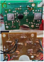

No problem. The worst part is it was functioning prior to the base lead on the old transistor breaking. So hopefully I just have the leads backwards.
Well based on testing the original transistor, the base is for sure in the middle lead. After getting the socket on the board, I tried them both ways, CE and EC with no results. Also got to test the the S8050 both directions.Transistor pinout is not standardized! It could be that the circuit originally used a transistor with an uncommon arrangement. Thus most replacements might not match the outline shown on the board.
I think we have E and C on the board figured out. The diode in the base circuit really limits the possibilities.
What I find puzzling is that, because of the diode, we should see around 0.7 volts DC on the base trace, even with the transistor removed, when the toy is trying to make sound. An AC measurement should be tiny, but non-zero.
It’s possible. But we did measure AC on the base earlier so I would not give up yet. Let me draw it up and think a bit…Well based on testing the original transistor, the base is for sure in the middle lead. After getting the socket on the board, I tried them both ways, CE and EC with no results. Also got to test the the S8050 both directions.
Could all this screwing around have killed the chip?
I'll get answers when I'm home later. Some spots were blank. I haven't removed anything but the transistor.OK, I've got a lot of questions:
1. C8, C9, R2 were never there? Or were they removed?
2. I can see the red/blk wires from the battery BT1. But there is another pair of red/blk wires near there. Do they go to a/the battery also?
2.1. If the other red/blk wires are to a battery, is it part of BT1 or a separate battery? How many cells in each?
3. R6 appears to be yellow-violet-gold-gold. Is this correct? If so it's 4.7 ohms.
4. R5 looks like yellow-violet-??. What are the other colors?
5. If the other red/blk wires are to a battery, I am not sure about their solder joints. One or two joints look bad, and once is may shorted. Can you check/re-do them?
Unless I am missing it, I don't see that the diode is connected to the transistor at all...
From battery minus:OK, I've got a lot of questions:
1. C8, C9, R2 were never there? Or were they removed?
2. I can see the red/blk wires from the battery BT1. But there is another pair of red/blk wires near there. Do they go to a/the battery also?
2.1. If the other red/blk wires are to a battery, is it part of BT1 or a separate battery? How many cells in each?
3. R6 appears to be yellow-violet-gold-gold. Is this correct? If so it's 4.7 ohms.
4. R5 looks like yellow-violet-??. What are the other colors?
5. If the other red/blk wires are to a battery, I am not sure about their solder joints. One or two joints look bad, and once is may shorted. Can you check/re-do them?
Unless I am missing it, I don't see that the diode is connected to the transistor at all...

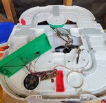

Unless I am missing it, I don't see that the diode is connected to the transistor at all...
In looking at the circuit board I really need to understand which traces are power and ground. How does the power switch work? It looks like 3 positions, so on, off, and ? Or is it just two positions? Since there are two black wires, where exactly does the center black wire go?

Beats me.Hope you know that transistor is not acting as a switch, but it is a single transistor audio amplifier. Not that I remember anything.
I didn't understand what a transistor was prior to this thread. I did read they are used as both solid state switches and audio amplifiers.Because of the fragility of the internal connections in a transistor and their relatively low prices I recommend you get a new one and replace the component with the broken lead.Beats me.
I've been wondering if I can solder some leads onto the original transistor since it was working prior to the base lead breaking.
Because of the fragility of the internal connections in a transistor and their relatively low prices I recommend you get a new one and replace the component with the broken lead.
The problem is the original type is unknown. The numbers on the transistor can't be read. The closest guess was a S8050 NPN, however it did not work. (I ordered a new one)Because of the fragility of the internal connections in a transistor and their relatively low prices I recommend you get a new one and replace the component with the broken lead.
Now that I've got the transistor socket I can test them easily. I just don't know what specs I need. I'm surprised it doesn't work with any of the transistors I've tried.Do a search for single transistor audio amplifier. You may find a number of a transistor that may work.
I tried. Couldn't get the solder to stick to the transistor. Maybe if the leads weren't broken off flush.Try to solder the legs on. Good practice for neural surgery. It’s dead as it sits so hard to kill it anymore. It may just Frankenstein it to work.
@FordTruckWench voltage on the left side of the resistor is 4.58 and the right side is 0.58, and 0.68 when pressing a switch. Checked it several times. Let go of the switch and voltage drops back down to 0.58 VDC.
I'd say the voltage change is instant. Definitely less than 1 second.Q: You say it drops back to 0.58. Does this happen right away, or a few seconds later?
Q: Are you sure you probed the right side of the Yellow-Violet-Yellow resistor? Not the Yellow-Violet-Gold. Not C8. Not the Red-Red-Brown resistor. Not the "vertical" stack of three solder points.
If you actually saw 0.58 to 0.68 volts on the base of the external transistor, that could be very good news. That means the device is trying to turn in on with the 0.68 volts.
Thinking out loud (this is directed more to Max): What if the transistor is a Darlington?

I'd say the voltage change is instant. Definitely less than 1 second.
Left gave 4.5 and right gave 0.58/0.68.

