To avoid these ads, REGISTER NOW!

Extra Outlets in my Shop

Model A Fan

Well-known member
Joined
Dec 1, 2011
Messages
1,223
Location
NW Washington
I'm just looking for confirmation this is done correctly. Outside of the first outlet being a GFI, is anything incorrect? Should I go back and put a GFI as the first outlet?

I haven't powered it up yet, but the run is powered by a 15A breaker. I'll be doing three more quad outlets on this breaker. Is that too many? I will only be using one piece of equipment at a time. Thank you!
 

Attachments

  • 20240308_154249.jpg
    20240308_154249.jpg
    924.3 KB · Views: 162
  • 20240308_163651.jpg
    20240308_163651.jpg
    709.3 KB · Views: 157
  • 20240308_163659.jpg
    20240308_163659.jpg
    473 KB · Views: 143
  • 20240308_163338.jpg
    20240308_163338.jpg
    599.5 KB · Views: 157
  • 20240308_163208.jpg
    20240308_163208.jpg
    430.8 KB · Views: 164
  • 20240308_163200.jpg
    20240308_163200.jpg
    477.7 KB · Views: 168
  • 20240308_154255.jpg
    20240308_154255.jpg
    914.6 KB · Views: 162
To avoid these ads, REGISTER NOW!

mm08822

Well-known member
Joined
Jan 13, 2012
Messages
6,051
Location
NJ
You could have eliminated the wagos in the receptacle box.

Buy some white.

First recept should be gfci. Change out what is needed to make that happen. Not sure pics are of the first recept on the circuit.
 
OP
M

Model A Fan

Well-known member
Joined
Dec 1, 2011
Messages
1,223
Location
NW Washington
You could have eliminated the wagos in the receptacle box.

Buy some white.

First recept should be gfci. Change out what is needed to make that happen. Not sure pics are of the first recept on the circuit.
I'll swap the first one for the GFI.

The first two pics are of the first outlet box.

I have the wagos as I got them for a little over $0.03/piece, so I figure why not. In the top junction box, I used a 5-way and 4-way Wagos as I plan to add more wire into that box and run it through the wall to the other side.
 
Last edited:
OP
M

Model A Fan

Well-known member
Joined
Dec 1, 2011
Messages
1,223
Location
NW Washington
Could I use one of these instead of a GFCI in the first outlet? If not, how/where do you use it?


I bought white THHN for this project and subsequent ones.


20240229_233445.jpg


20240229_233453.jpg
 

PCustoms

Well-known member
Joined
Jul 23, 2011
Messages
23,444
Location
VT
Could I use one of these instead of a GFCI in the first outlet? If not, how/where do you use it?


I bought white THHN for this project and subsequent ones.


20240229_233445.jpg


20240229_233453.jpg
No.

That's surge suppression, not ground fault.

As previously stated the black with white tape is not allowed.

I would also not use the blue backed outlet shown in your first post, that's $0.70 outlets area about the cheapest thing you can buy and don't hold up.

Other then that no safety issues I see.
 

loganb

ALLIANCE MEMBER
Joined
Dec 29, 2011
Messages
5,626
Location
Omaha, NE
Just curious, wouldnt it be easier to just use a GFCI breaker ?

Gfci outlets are cheaper than breakers, sometimes substantially depending on panel type. Some people also aren't comfortable swapping a breaker in a live panel....so the common solution is the first receptacle solution. Not sure one is that much faster or simpler than the other.
 

Higgins

Well-known member
Joined
Dec 25, 2009
Messages
1,942
Location
Shepheardsville, KY
Socket replacement is lest costly and quicker !!!

Case in point… we had a church member had her fridge go out. Turned out it was a CB in the electrical panel in the lower basement level. They had lived there over 40 yrs and never had to look into electrical panel.
We changed out the CB and installed a GFI with the green/red LED.
 
OP
M

Model A Fan

Well-known member
Joined
Dec 1, 2011
Messages
1,223
Location
NW Washington
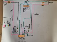
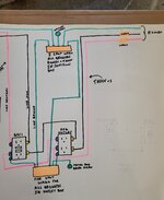
So I just installed the GFCI into the box. I'm using a double outlet cover and wanted a second outlet in that slot. That made it more complicated, but I think I figured it out. 😅

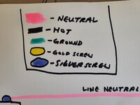
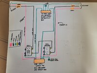
I've drawn out the circuit to show the wiring (wires are harder to photograph).

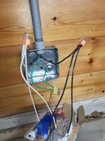
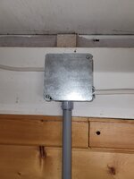
Basically I have Romex feeding THHN in 1/2" conduit as the line. They are "Wago'd" together at the junction box. The Romex feeds the first 3-strand of THHN down the conduit to the GFCI.

In the metallic box, I have the GFCI fed by THHN. The first set of THHN is connected to the GFCI at the TOP posts (black to gold, white to silver).

I then have a short wire running from the BOTTOM posts of the GFCI to the TOP posts of the regular outlet (black to gold, white to silver again).

From there, I have three more THHN strands running BACK UP the conduit to the Romex waiting up top. This second set of THHN is connected to the BOTTOM posts of the regular outlet. I believe this is considered "LOAD".

In both metallic boxes, there is a ground screw I attached a grounding wire to and put it into the 5-way Wago. Inbound Romex Ground, both sets of THHN grounds, metallic box ground, and outbound Romex are all Wago'd together in the top metallic junction box.

In the bottom box, I have both THHN grounds, ground "jumper" for GFCI, ground "jumper" for regular outlet, and metallic box grounding wire.

If need be, I'll eliminate the second outlet in this box to save the headache of this set up. But I think I have it correct. I'm not an artist, but I've tried to (amateurishly) draw the circuit. It's not fed live, it is not currently hooked up to power. I appreciate all help and criticism. I've also attached real pics. Romex is roughly 9' in the air between a wall and floor joist in a barn.

Is it OK to have all the grounds Wago'd together like this?

20240310_174044~2.jpg
20240310_173838.jpg
20240310_173918.jpg
20240310_173847~2.jpg
20240310_173852~2.jpg
20240310_173902~2.jpg
20240310_173905~2.jpg
20240310_173918~2.jpg
20240310_174029~2.jpg
20240310_174037~2.jpg
 

PCustoms

Well-known member
Joined
Jul 23, 2011
Messages
23,444
Location
VT
Sorry, can't follow that.

Seems that you have a lot of grounds in the box, you don't need a "to" and "from".

Also the line should feed the GFCI on the "line" side, then all outlets from there on should be fed from the "load" side of that GFCI.

This may have been a case where a breaker was better, again I can't follow your diagram.

Where did the romex come from, was that pre-existing?
 

sparky 1971

Well-known member
Joined
Oct 9, 2018
Messages
8,005
Location
Central Iowa
It's fine. An extra ground wire isn't going to hurt anything. One thing that I would do is connect the wires from the load side of the GFCI to the wires leaving, and pigtails to the standard receptacle.
 

sparky 1971

Well-known member
Joined
Oct 9, 2018
Messages
8,005
Location
Central Iowa
Sure it works, but it isn't needed and can affect box fill
Two #12 hot, two neutrals, two grounds, and two devices require 20.25 cubic inches. The box is 21.0 and a raised cover is 6.5. It's not needed, but no different than if it had two sets of romex cables running to and from it.
(and be a headache).
I fail to see how sticking one wire under a Wago is a headache. Once again, it's no different than two romex cables. And, I realize there isn't a picture of the box with the GFCI, but the pictures that are posted show one ground wire in the pipe.
@Model A Fan is the "line" on the left of your sketch your feed side?
Ya suppose maybe he took the feed to the standard receptacle then from there to the GFCI?
 

PCustoms

Well-known member
Joined
Jul 23, 2011
Messages
23,444
Location
VT
Two #12 hot, two neutrals, two grounds, and two devices require 20.25 cubic inches. The box is 21.0 and a raised cover is 6.5. It's not needed, but no different than if it had two sets of romex cables running to and from it.

I fail to see how sticking one wire under a Wago is a headache. Once again, it's no different than two romex cables. And, I realize there isn't a picture of the box with the GFCI, but the pictures that are posted show one ground wire in the pipe.

Dunno man, just pointing out it's redundant and not needed. Personally whenever I can minimize wires in a conduit of box it seems easier to me.

Ya suppose maybe he took the feed to the standard receptacle then from there to the GFCI?

Not sure. When I glanced at the pics initially I didn't get it. With all the weird things we see here thought it's worth clarifying that his string of outlets are fed correctly.
 
OP
M

Model A Fan

Well-known member
Joined
Dec 1, 2011
Messages
1,223
Location
NW Washington
Sorry, can't follow that.

Seems that you have a lot of grounds in the box, you don't need a "to" and "from".

Also the line should feed the GFCI on the "line" side, then all outlets from there on should be fed from the "load" side of that GFCI.

This may have been a case where a breaker was better, again I can't follow your diagram.

Where did the romex come from, was that pre-existing?

Ground #1-Romex ground coming from breaker panel to junction box Wago
Ground #2-THHN "No. 1" running from junction box Wago down conduit to Wago in switch box
Ground #3-Ground Screw in switch box connected to Wago
Ground #4-THHN "No. 2" running from Wago in switch box back up conduit to junction box Wago
Ground #5-Ground screw in junction box connected to Wago
Ground #6-Romex ground connected to junction box Wago leaving junction box to next junction box

The "line" (as indicated on my diagram) is the wire coming directly from the breaker to the GFCI. The Romex connects with the first THHN group running down the conduit. The neutral THHN is connected to the top silver screw, hot THHN to the top gold screw and the grounding THHN wire is connected to the Wago.

The "load" terminals (as I understand it) are the bottom screws. There is a short piece of black THHN to connect the gold "load" screw on the GFCI to the top gold "line" screw on the second/regular outlet. There is a short piece of white THHN to connect the silver "load" screw on the GFCI to the top silver "line" screw on the second/regular outlet.

From there, the second set of THHN is connected to the bottom screws on regular/second outlet to go back up the conduit to the Romex that is "leaving" the junction box.

I installed the Romex on this project and was under the impression that it was OK to run it like that. It is not hooked up to any power source, yet.

Sure it works, but it isn't needed and can affect box fill (and be a headache).

@Model A Fan is the "line" on the left of your sketch your feed side?
The "line" is the feed side, it runs from the breaker to the junction box and powers the inner workings.

Could the two sets of white/black THHN have shared one ground wire?

Two #12 hot, two neutrals, two grounds, and two devices require 20.25 cubic inches. The box is 21.0 and a raised cover is 6.5. It's not needed, but no different than if it had two sets of romex cables running to and from it.

I fail to see how sticking one wire under a Wago is a headache. Once again, it's no different than two romex cables. And, I realize there isn't a picture of the box with the GFCI, but the pictures that are posted show one ground wire in the pipe.

Ya suppose maybe he took the feed to the standard receptacle then from there to the GFCI?
Feed is going to the GFCI top screws first, from GFCI bottom screws to the top screws on the standard receptacle, and from the bottom screws on the standard receptacle back up to the Romex that leaves the junction box and heads down the line.
Dunno man, just pointing out it's redundant and not needed. Personally whenever I can minimize wires in a conduit of box it seems easier to me.


Not sure. When I glanced at the pics initially I didn't get it. With all the weird things we see here thought it's worth clarifying that his string of outlets are fed correctly.
Basically the Romex coming in is connected to THHN which runs down the conduit to the GFCI's top screws. The bottom screws have small wires running from them to the top screws of the standard receptacle. The standard receptacle has THHN running from its bottom screws to the junction box where it connects back to the Romex in the junction box and back outside to the next junction box.

I'm sorry if this is a little difficult to follow. I've tried to use correct terminology, but might have missed it in a few places. Thank you for your assistance everyone! :D
 

dave*99

Well-known member
Joined
May 5, 2009
Messages
4,280
Location
Coastal NJ
I believe what you have connected will work. Pop the GFCI test button and confirm the downstream receptacles go dead.

Small issue, you only need 1 ground wire in your vertical conduit. Either ground 2 or 4 is redundant.

Ground #1-Romex ground coming from breaker panel to junction box Wago
Ground #2-THHN "No. 1" running from junction box Wago down conduit to Wago in switch box
Ground #3-
Ground Screw in switch box connected to Wago
Ground #4-THHN "No. 2" running from Wago in switch box back up conduit to junction box Wago
Ground #5-
Ground screw in junction box connected to Wago
Ground #6-Romex ground connected to junction box Wago leaving junction box to next junction box
 
To avoid these ads, REGISTER NOW!
OP
M

Model A Fan

Well-known member
Joined
Dec 1, 2011
Messages
1,223
Location
NW Washington
I believe what you have connected will work. Pop the GFCI test button and confirm the downstream receptacles go dead.

Small issue, you only need 1 ground wire in your vertical conduit. Either ground 2 or 4 is redundant.
Thank you for the info, I had begun to understand that after reading the other replies. What is the "science/theory" behind how that works? I find that by understanding the way something works helps me to do the project better (because I know how and why something is supposed to be a certain way). Sometimes "I just gots ta know".

How does one ground between both sets of black/white THHN provide adequate grounding for both sets of THHN?

As for the GFCI, I'll have to connect the Romex into the box before I can test it, but I'm hoping that will be next weekend. I have 2-3 more boxes to wire on this circuit so I can have lighting and equipment plugged into it. I'm overcoming my barn's status as storage space by installing lighting and outlets because that's what its been for so many years. Now I'll be able to work in my shop without running extension cords across the floor to my different pieces of equipment.
 

dave*99

Well-known member
Joined
May 5, 2009
Messages
4,280
Location
Coastal NJ
How does one ground between both sets of black/white THHN provide adequate grounding for both sets of THHN?
There are 2 ways to look at this. You ran 2 wires in parallel from wago to wago. Only 1 wire of sufficient gauge is needed. If you had a fault from a 20A circuit hit your ground wire you only need to carry 20A in the ground wire. Not 40A. It’s a tad more complicated but that is the basics.

The other concept is all the grounded components in a 20A circuit need a 20A path to the service panel. This carries the trip or fault current needed for the breaker to act. The grounding conductors serve to tie it all together. Touch a live wire to anything connected to that ground wire and pop goes the breaker.
 
Last edited:

sparky 1971

Well-known member
Joined
Oct 9, 2018
Messages
8,005
Location
Central Iowa
Feed is going to the GFCI top screws first, from GFCI bottom screws to the top screws on the standard receptacle, and from the bottom screws on the standard receptacle back up to the Romex that leaves the junction box and heads down the line.
It's perfect as long as the top set of screws is the line side. The GFCI receptacles I use have the line terminals on the bottom.
 
OP
M

Model A Fan

Well-known member
Joined
Dec 1, 2011
Messages
1,223
Location
NW Washington
There are 2 ways to look at this. You ran 2 wires in parallel from wago to wago. Only 1 wire of sufficient gauge is needed. If you had a fault from a 20A circuit hit your ground wire you only need to carry 20A in the ground wire. Not 40A. It’s a tad more complicated but that is the basics.

The other concept is all the grounded components in a 20A circuit need a 20A path to the service panel. This carries the trip or fault current needed for the breaker to act. The grounding conductors serve to tie it all together. Touch a live wire to anything connected to that ground wire and pop goes the breaker.
I'm doing all this on a 15A breaker, but I'm assuming I can just use 14AWG for the 15A circuit. If it works as it is, I may just leave the duplicate ground wire. The only benefit would be I could remove the 5-way Wagos and save them for later and just use the 4-way ones in their place after I remove a redundant ground wire from the conduit.
It's perfect as long as the top set of screws is the line side. The GFCI receptacles I use have the line terminals on the bottom.
These GFCI outlets are taped on the bottom terminals when new from the package, so I was using the top terminals as the "line" and the bottom as the "load" (feeding the standard receptacle's top screws and then the outgoing Romex connects to the bottom screws via the second set of THHN).
 

djbmw

Well-known member
Joined
Jun 20, 2013
Messages
1,168
Location
Ottawa, Ontario, Canada
If you want to do this to code then the romex cannot be exposed. It must be within a wall and/or conduit. Alternatively you can use armoured cable. Additionally, ensure you have the correct stapling/securing of the wire.
 

Norcal

Well-known member
Joined
Mar 16, 2008
Messages
13,769
If you want to do this to code then the romex cannot be exposed. It must be within a wall and/or conduit. Alternatively you can use armoured cable. Additionally, ensure you have the correct stapling/securing of the wire.
AC or MC cable does not give you a pass over NM sheathed cable "Romex"®, they are subject to similar rules as NM cable to be protected from physical damage.
 
  • Like
Reactions: Max

djbmw

Well-known member
Joined
Jun 20, 2013
Messages
1,168
Location
Ottawa, Ontario, Canada
AC or MC cable does not give you a pass over NM sheathed cable "Romex"®, they are subject to similar rules as NM cable to be protected from physical damage.
Im in Canada so the CEC applies and, for us, Rule 12-518 in the CEC states, "Protection for cable in exposed installations", and does allow for AC to fit the requirement.
 
  • Like
Reactions: Max

Max

ALLIANCE MEMBER
Joined
Jun 16, 2018
Messages
3,351
Location
Georgia
Im in Canada so the CEC applies and, for us, Rule 12-518 in the CEC states, "Protection for cable in exposed installations", and does allow for AC to fit the requirement.
Works for you, but not the OP that is in the US...
 
OP
M

Model A Fan

Well-known member
Joined
Dec 1, 2011
Messages
1,223
Location
NW Washington
So, should I strip the Romex off and install some conduit? It adds a little expense, but it is nothing outrageous. Having the exposed Romex makes it easier to modify/see where the wire is instead of burying it in a wall.
 

PCustoms

Well-known member
Joined
Jul 23, 2011
Messages
23,444
Location
VT
So, should I strip the Romex off and install some conduit? It adds a little expense, but it is nothing outrageous. Having the exposed Romex makes it easier to modify/see where the wire is instead of burying it in a wall.
Code wise, probably.

Practically, leave it.

Every basement I've ever been in has wiring that is "exposed", yet somehow all these houses passed an inspection.
 

sparky 1971

Well-known member
Joined
Oct 9, 2018
Messages
8,005
Location
Central Iowa
So, should I strip the Romex off and install some conduit? It adds a little expense, but it is nothing outrageous. Having the exposed Romex makes it easier to modify/see where the wire is instead of burying it in a wall.
It looks to me like the Romex is run at the top of the wall so it's up to you. By code, it has to be protected from physical damage, but there is no definition of what that is, leaving it wide open to the interpretation of the AHJ and that is you if there are no inspections going to happen. There are places where it would pass as is, others it would have to be in conduit. If it's where I think it is, about the only damage that could happen aside from leaning tall things against the wall .is from rodents, and for some reason, mice find the jacket on romex tasty. I've been in many barns to find romex completely chewed down to bare conductor.
 

Norcal

Well-known member
Joined
Mar 16, 2008
Messages
13,769
If Romex® has the jacket stripped off to use the individual conductors in conduit, it is scrap metal since the conductors are not marked it is not a recognized wiring material code wise.
 
OP
M

Model A Fan

Well-known member
Joined
Dec 1, 2011
Messages
1,223
Location
NW Washington
Code wise, probably.

Practically, leave it.

Every basement I've ever been in has wiring that is "exposed", yet somehow all these houses passed an inspection.
The barn when I bought the place had Romex running through holes in the rafters. Its worked fine for decades, so that's why I chose to run it the way I did.
It looks to me like the Romex is run at the top of the wall so it's up to you. By code, it has to be protected from physical damage, but there is no definition of what that is, leaving it wide open to the interpretation of the AHJ and that is you if there are no inspections going to happen. There are places where it would pass as is, others it would have to be in conduit. If it's where I think it is, about the only damage that could happen aside from leaning tall things against the wall .is from rodents, and for some reason, mice find the jacket on romex tasty. I've been in many barns to find romex completely chewed down to bare conductor.
I appreciate the insight. My barn cats seem to take care of the ROUS. I have had to chase a possum and racoon out, but so far the worst pests are flies that seem to breed like crazy. I vacuum them up every so often so their carcasses aren't littering my window sills and work benches.
If Romex® has the jacket stripped off to use the individual conductors in conduit, it is scrap metal since the conductors are not marked it is not a recognized wiring material code wise.
Can I run Romex through conduit and be within regs? I will refrain from stripping the jacket off and using the unmarked wire as THHN. Too bad it isn't marked, I'm sure it would not cost much to mark it like THHN is marked.
 

sparky 1971

Well-known member
Joined
Oct 9, 2018
Messages
8,005
Location
Central Iowa
Not supposed to do that. I'd just buy the THHN...
Sure you can, unless there is a written amendment against it.
My bad... I was always taught it was a no-no... Locally... My inspector won't pass it. NO IDEA why but he won't.
The inspector is either an idiot or there is an amendment in place, but I can't think of one good reason to prevent Romex from being in conduit. The NEC even lists most, if not all, types of conduit as acceptable for running Romex in to protect it.

We do have one thing in our amendments that I don't like. I forget the exact wording, but it basically says the inspector is always right. I haven't had a problem with it yet but the potential is always there, maybe you have something similar and he just doesn't like it.
 
To avoid these ads, REGISTER NOW!
Top Bottom