Sorry, can't follow that.
Seems that you have a lot of grounds in the box, you don't need a "to" and "from".
Also the line should feed the GFCI on the "line" side, then all outlets from there on should be fed from the "load" side of that GFCI.
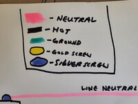
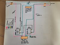
This may have been a case where a breaker was better, again I can't follow your diagram.
Where did the romex come from, was that pre-existing?
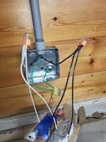
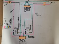
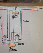
Ground #1-Romex ground coming from breaker panel to junction box Wago
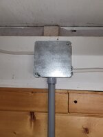
Ground #2-THHN "No. 1" running from junction box Wago down conduit to Wago in switch box
Ground #3-Ground Screw in switch box connected to Wago
Ground #4-THHN "No. 2" running from Wago in switch box back up conduit to junction box Wago
Ground #5-Ground screw in junction box connected to Wago
Ground #6-Romex ground connected to junction box Wago leaving junction box to next junction box
The "line" (as indicated on my diagram) is the wire coming directly from the breaker to the GFCI. The Romex connects with the first THHN group running down the conduit. The neutral THHN is connected to the top silver screw, hot THHN to the top gold screw and the grounding THHN wire is connected to the Wago.
The "load" terminals (as I understand it) are the bottom screws. There is a short piece of black THHN to connect the gold "load" screw on the GFCI to the top gold "line" screw on the second/regular outlet. There is a short piece of white THHN to connect the silver "load" screw on the GFCI to the top silver "line" screw on the second/regular outlet.
From there, the second set of THHN is connected to the bottom screws on regular/second outlet to go back up the conduit to the Romex that is "leaving" the junction box.
I installed the Romex on this project and was under the impression that it was OK to run it like that. It is not hooked up to any power source, yet.
Sure it works, but it isn't needed and can affect box fill (and be a headache).
@Model A Fan is the "line" on the left of your sketch your feed side?
The "line" is the feed side, it runs from the breaker to the junction box and powers the inner workings.
Could the two sets of white/black THHN have shared one ground wire?
Two #12 hot, two neutrals, two grounds, and two devices require 20.25 cubic inches. The box is 21.0 and a raised cover is 6.5. It's not needed, but no different than if it had two sets of romex cables running to and from it.
I fail to see how sticking one wire under a Wago is a headache. Once again, it's no different than two romex cables. And, I realize there isn't a picture of the box with the GFCI, but the pictures that are posted show one ground wire in the pipe.
Ya suppose maybe he took the feed to the standard receptacle then from there to the GFCI?
Feed is going to the GFCI top screws first, from GFCI bottom screws to the top screws on the standard receptacle, and from the bottom screws on the standard receptacle back up to the Romex that leaves the junction box and heads down the line.
Dunno man, just pointing out it's redundant and not needed. Personally whenever I can minimize wires in a conduit of box it seems easier to me.
Not sure. When I glanced at the pics initially I didn't get it. With all the weird things we see here thought it's worth clarifying that his string of outlets are fed correctly.
Basically the Romex coming in is connected to THHN which runs down the conduit to the GFCI's top screws. The bottom screws have small wires running from them to the top screws of the standard receptacle. The standard receptacle has THHN running from its bottom screws to the junction box where it connects back to the Romex in the junction box and back outside to the next junction box.
I'm sorry if this is a little difficult to follow. I've tried to use correct terminology, but might have missed it in a few places. Thank you for your assistance everyone!