OP
lilscorpion
Well-known member
Quality work as always Matt! Happy New Year!
Thanks Mike, Happy New Year to you and your family as well!

Quality work as always Matt! Happy New Year!


") but it works fabulously in situations like this too.
but it works fabulously in situations like this too.


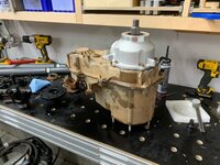
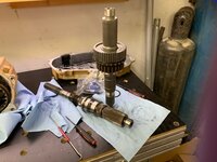


It's funny you documented the SYE process as I was just thinking about it the other day. When I was 16, basically your son's age, this was so intimidating, but every lifted Jeep guy had to deal with the NP231 at one point or another. My dad isn't mechanical, so all I had to go off of was the black and white photo instructions. It's funny to look back at now as this is such an easy process, especially with the various guides people have put together online. No doubt you've been teaching your son mechanics his whole life, but I guarantee he will remember this SYE kit install and he will be more comfortable taking on driveline projects in the future as a result.
She's coming along fantastic Matt.
I hear ya on good (within spec) vs. perfect. Sometimes that's a tough call.
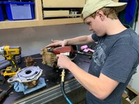
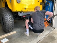
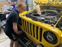
I noticed the snow on the ground in the background and Andrew in shorts and that alone made me chilled.
Thanks Mike. Truth he told, Andrew wears shorts mostly because the garage stays a mild 68* while we’re working in there. On those days where we keep opening the garage though he pays for it. That day was as cold as you were guessing, he was freezing his *** off while the door was open.
 To this day, I hate working in cold weather.
A little discomfort will make him appreciate what he has or doesn't have. I remember having to do a clutch on the ground in sub-freezing temps when I was in college.

Uh, ya, just a little bit..I think I'm definitely spoiled nowadays.
I know what you mean Mark. I started working in my parent's carport on their house with my little Craftsman toolbox in the back of my SUV back in the early 80's. In my dad's workshop I had two 55-gallon drums with a piece of plywood as a work bench and in the cold months I was bundled up in my insulated coveralls. I told my son he doesn't have a clue how easy and nice he has it to be able to work in a climate controlled shop even if it's sub-zero temps outside.
I think I'm definitely spoiled nowadays.
 Those were the days when we didn't give a sh*t about where we worked on cars, we loved it anyway and it saved us money we didn't have....


Enjoying the updates.
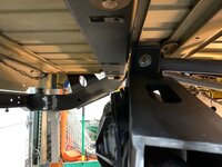
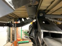
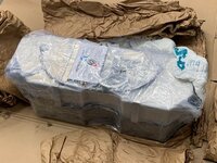
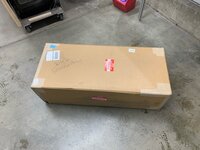
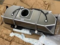
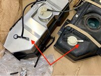
Your tank install seems to be going like most of my projects...
"This should bolt right in" after overcoming half a dozen obstacles.
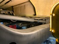
We’ve had quite a few roadblocks on this project. At one point Andrew got frustrated when we learned that where we relocated the factory washer tank was exactly where the PSC power steering reservoir needed to be. He said “I wish we would have just done a simple 4-inch lift and been done with it. I’d be driving it already”.
To that I replied - “dude, we’re building a custom rig using a mountain of products that are designed to be used universally on many different model years all of which require tweaks and adjustments to work with the other parts we’ve used the specific way you and undecided to use them. ”
He simply replied "because the LJ looked liked every else's LJ and I wanted something completely unique that I could call my own". That's when I got it.

Funny you mentioned that Matt. My son and I had the exact same discussion but it was the other way around.
Last year when we cut the entire undercarriage out from under his WJ and started building his long-arm suspension and then again when we were trying to build the bumper and do the tank tuck I was getting frustrated because it didn't fit into "my" schedule. I questioned why he sold a perfectly fine LJ that was lifted and done and ready to drive for one that we would have to build from scratch nearly everything. He simply replied "because the LJ looked liked every else's LJ and I wanted something completely unique that I could call my own". That's when I got it.


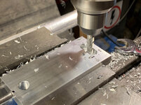

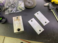


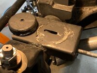
Nice process of elimination and figuring out your problems. its nice to have the tools to be able to just fab up new mounts and spacers as you need them. Andrew is getting quite the education on this project.
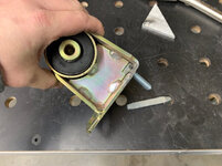
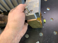
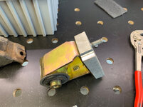
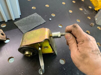
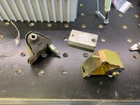
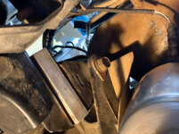
Installing the motor mount lift was the most aggravating part of my TJ build. You described it perfectly. One side came apart easily, the other was a battle. My Jeep was bone stock and easier than what you went through.
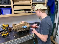
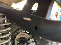
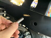
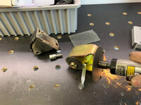
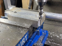
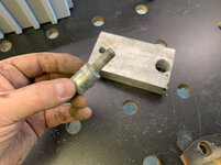
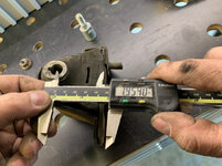
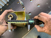
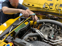
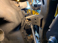
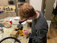
Initially I had hoped Andrew would learn a thing or two about vehicles in the process especially since the trade classes are no longer offered in public schools. It’s turned into quite a bit more throughout the build. I came home from work the other day and found him finishing up his first self-directed fab project. He’d found that the air box was interfering with a headlight ballast and decided to solve it himself. He used the cut-off wheel, trimmed the interfering piece off, shifted it forward to fill a void, and welded it back on. To do so he had to figure out how to set the voltage and wire speed on the welder...I was half relieved he didn’t hurt himself with the cutoff wheel and half impressed he did it all himself.
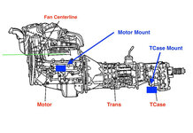
We also used the M.O.R.E taller motor mounts but we didn't have the previous owner's mess to have to contend with like you did. Once we got it close we did still have to alter the fan shroud slightly but I ended up elongating the holes in the shroud and adjusting as needed and everything worked perfectly.


Beautiful work as always Matt.
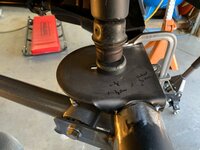
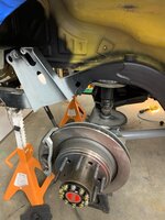
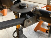
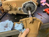
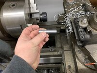
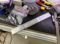
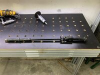
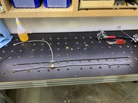
The drag link and pitman arm turned out very nice.
Is it close to being a driver?


Congrats!
Looks great.
That had to be a very satisfying test drive for both of you.


