To avoid these ads, REGISTER NOW!

G1K's Triumph TR-6 project - in progress

OP
G

G1K

Well-known member
Joined
Feb 10, 2005
Messages
1,073
Location
Buffalo, NY
The machining on the pulley is finished. Here are the rest of the steps.

To machine the front face I had to flip the part and re-indicate the part to get it true. I had a little movement on the .0005 indicator, perhaps 3 or 4 tenths. That's probably within Fords specification.


Next a facing cut on the front:


and the birds nest that resulted from not clearing the chips away quick enough:


The next step was to drill a pilot hole in the front face, then bore it out to .630 for a very tight fit to the waterpump shaft. I forgot to get photos of the boring.

Then some cosmetic appeal, a 45 degree face on the front


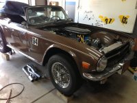
The next step was to take the pulley off the lathe, put it on the water pump which was mounted on the engine and measure how much to cut from the back flange face to get everything to center. I did this in 2 steps, indicating the diameter and outside face each time to make sure the alignment was correct. No photos on this step.. :(

Next, the bolt holes were drilled on the mill:


The the pulley is ready for vibratoy deburr on Monday. Here's what aftermath of cutting down the bar looks like:


And the pulley


After deburring, I hope to have have is sulfuric acid anodized and dyed black. I'll have some photos of that by Wednesday.

Ryan
 
Last edited:
To avoid these ads, REGISTER NOW!
OP
G

G1K

Well-known member
Joined
Feb 10, 2005
Messages
1,073
Location
Buffalo, NY
Thanks Ed. That's the same reason I've been following your thread.

One last photo, engine and the upper frame brace installed (not bolted in). There's so little clearance between the steering rack and the engine pulley I may have to remove the pulley to change belts. The other option is to machine pulleys for vee belts.


The upper frame brace will need a notch, fortunately it can be fabricated off the car. The steering rack mount will also need a slight modification and reinforcement.

Next up, I need to figure out the routing for the hose to the heater core and heater control valve.

Also on the list are researching which amphenol connector to use as a bulkhead connector for the wiring harness, an alternator mounting bracket and belt tensioner, exhaust and driveshaft fab.

The light at the end of the tunnel is very small, but at least I can see it.

Ryan
 
OP
G

G1K

Well-known member
Joined
Feb 10, 2005
Messages
1,073
Location
Buffalo, NY
The next installment of “Things are getting tight in here”

Not many photos, but quite a lot of fab completed.

Bracket and turnbuckle to hold the alternator (Ford 3G 130A) and tension the belt. The lower bracket is missing in the photo, but will connect the alternator mount bolt to the two closest W/P bolts..


I also mocked up the steering. 4 u-joints are needed to get everything to line up, and two spherical bearings to keep the shafts from wobbling about. I have the actual shafts mocked up with oak dowels for now, until I’m sure of the lengths. The final shafts will be .750 diameter .120 wall steel tubing. The new wiring harness is in the photo also.


The throttle system is complete. I made a hybrid pedal system using a Mr. Gasket “hot rod” pedal for the mount, and the original TR-6 pedal for the actual pedal. No photo of the pedal arrangement, I’ll take one this weekend.
I need to find a clean way to route the plug wires. Right now it looks like an octopus is trying to mate with the intake. Also shown in the photo is the coil mount (way overkill), the mockup of the heater hoses and the mega-fuse holder made from black delrin.


The engine is back out now to finish up the steering mounts, relocated body mounts and radiator mounts and cut off the driver’s side original motor mount to provide clearance for the oil filter.


While it’s out I’ll finish pluming the oil pressure gage, final fitting the alternator brackets, fuel lines etc.

I picked up a few Volvo 2 speed fan relays, a Taurus two speed fan and a few other odds and ends today at the pick and pull. It was rather empty, 15 degrees and blowing snow. I went prepared with a list and the locations of the cars I needed to grab parts from and lucked out, the first on each list for a specific part had what I needed and in 45 minutes I was back in the warm car headed home. I'll get some photos of the haul up tomorrow.

The weeks plan include new front body mounts, and the radiator mounts. The rad should be here on Friday, its a Ford style double row aluminum rad with welded tanks. I made a mock up from some foam, and the Taurus fan will fit it perfectly.

Until next time...

Ryan
 
Last edited:
OP
G

G1K

Well-known member
Joined
Feb 10, 2005
Messages
1,073
Location
Buffalo, NY
I got into a groove today and forgot to take a lot of photos, but I did get a few.

The first thing today was to cut off the front body mounts, they were interfering with where the new radiator needs to go. Here's the area with the old mounts removed:


I use a 2*3 inch tube, split down the middle, one for each side of the car. I made a cardboard template to get the angles correct then welded it in

Drivers side from the engine bay:


and the passenger side from the wheel well:


At about 10:30 this morning, FedEx dropped off the new radiator, a day early. The fan I salvaged from the Taurus was too large. The the shroud was too wide by about 2.5". I cut the shroud down then welded the end back on. This is the first time I have been successful using the hot air welder. It' not pretty yet, but very solid. I used this strips of the section of the shroud I removed as filler rod and pretended I was tigging the plastic. It worked. To cool each weld and flatten the plastic, I use the head of a bolt.


And the fit on the radiator:


Outlet coped in:


and final fit:


The weld bead sanded out okay, but I think some filler and a coat of paint on the whole shroud will make it look 100% better.

Next up are the lower rad mounts. I made up "U" shaped brackets, with the vertical portions of the U angled to tip the radiator forward.

A shot of the weld cooling:


and the driver side welded in place (also shows a more clear shot of the body mount):


It was only 9 degrees here today, and projections for tomorrow are for 0. Provided I can get the garage heated to a reasonable level, the plan is for the upper radiator mounts, and finish the accessory brackets on the engine. Hopefully I can do that before lunch, and start the wiring in the afternoon.

That's all for today.

Ryan
 
OP
G

G1K

Well-known member
Joined
Feb 10, 2005
Messages
1,073
Location
Buffalo, NY
It's been a while since I have updated the thread, and a bit more work has been completed.

The new wiring harness is in, terminated, and shrink wrapped / loomed where appropriate and tested. The engine is back on the stand to have a few things cleaned up (oil pressure sender mounting, alternator mounting etc) and the clutch installed.

The new dash is nearing completion, I have some book-matched walnut burl that I'll be veneering this weekend.

What's left: Drive shaft, mount new differential, re-install interior, exhaust, and the brake and fuel lines.
I'll take and post some photos this weekend

Ryan
 

NASTYZEN

Well-known member
Joined
Jun 11, 2010
Messages
2,823
Location
St-Colomban,Que. Canada
Just seen this thread for the first time. Wow, that's a big engine in a small car!
Cool project, skills and lathe. :thumbup: I'll catch up on this later on tonite for sure
 
OP
G

G1K

Well-known member
Joined
Feb 10, 2005
Messages
1,073
Location
Buffalo, NY
Another quick update - it runs :)

I will have the drive shaft made locally on Thursday and should have the car moving under it's own power by the weekend. Photos will be forthcoming.

Ryan
 
OP
G

G1K

Well-known member
Joined
Feb 10, 2005
Messages
1,073
Location
Buffalo, NY
Here's a comparison shot of the old u-joint and slip yoke rear axle to the new CV axle.

attachment.php


Engine bay

attachment.php


And a side shot of the car

attachment.php


I'm going to need to figure out how to make the air cleaner fit with out putting a scoop on the hood - there may not be the clearance I originally calculated...

Ryan
 

Attachments

  • axles.jpg
    axles.jpg
    135 KB · Views: 364
  • engine04.jpg
    engine04.jpg
    144 KB · Views: 371
  • car01.jpg
    car01.jpg
    132.7 KB · Views: 383

johno

Well-known member
Joined
Oct 16, 2009
Messages
2,418
Location
Southern Ont.
I like this project a lot.

I'm curious wouldn't a rear sump engine have been easier to fit, or is there another issue?
 
OP
G

G1K

Well-known member
Joined
Feb 10, 2005
Messages
1,073
Location
Buffalo, NY
I let this thread of the TR6 build get way behind, my apologies to those that have been following and waiting for an update. Today’s post is concerning the dash board.

The stock smith gauges are not an easy conversion (not at all for the tach AFAIK) to adapt for a V8, so I found a set from New Vintage USA, who have been extremely helpful with a few of the minor issues I’ve had. I’ll give some details in a later post.
The NVU speedo and tach are smaller than the Smith units – so either an insert is needed for the stock dash, or a new dash needs to be fabricated. I chose the latter. I found a nice set of consecutive cut walnut burl veneer on ebay. I read as much as I could about the veneering process. I was tempted to vacuum bag, but that would mean diverting time to build a vacuum set up. I chose to go with a cold press.
The substrate is ½” cabinet grade ply (next time I will use MDF). I laid out the gauge configuration using the stock dash as a template. All holes cut and sanded, each gauge checked and double-checked for fit. I tried different orientations of book-matching the veneer and settled on this pattern.


An interesting problem came up during the construction – the glove box door. There are three obvious options, 1 – veneer the piece then cut the door out and 2 - cut the door out then veneer the pieces separately or 3 - cut the door out and put it back in place during veneering. I’m not steady enough to do option 1, a slight mistake with the router (which needs a 1/16” cutting bit to minimize door gap) and the whole piece would be junk. The problem with the 2nd option is how to keep the pattern of the veneer matched, and the problem with 3 is how to keep the door centered during the veneering glue up so it doesn’t glue itself back to the main dash or wind up with an uneven gap.

What I found worked was to cut the door out from the dash first, then screw the dash to a backer and also screw the door to the backer. I was able to set the door gap perfectly and there was no possibility of any shifting during glue up.

I trimmed the edges of the veneer to make sure the book-matching would be square with as little gap as possible between the sheets. Each sheet was taped together and the outside cut roughly to shape. The glue was rolled onto the ply, the veneer laid down and everything sandwiched in a make shift press. 4 sets of clamps and cauls as well as 210 lbs of dumbells kept a reasonable force on the veneer as the glue dried.


The moment of truth was the ~12 hours later when everything came apart and the dash emerged.


It’s starting to look like a dash. The next steps were to trim the veneer from the holes, sand progressively but lightly – the veneer is not thick, cut the door free and start with the stain, ploy and sand, poly and sand and repeat over and over. Once done, I could finally and populate the dash with the gauges, indicators, switched and hardware.

Here is a photo of the dash installed in the car. It came out reasonable well however there are some flaws. The next version will be much improved should I decide to redo it. The photos don’t really show the “depth” of the burl, perhaps when the sun finally shines here I can get better shots outside.

please excuse the dust, finger prints and grime...


Night:


And a shot outside in semi sun light (again, please excuse the mess - carpet, hanging heater hoses etc)


Ryan
 
Last edited:
OP
G

G1K

Well-known member
Joined
Feb 10, 2005
Messages
1,073
Location
Buffalo, NY
I like this project a lot.

I'm curious wouldn't a rear sump engine have been easier to fit, or is there another issue?

Johno,
I'm not very familiar with the differences between dual sump and single rear sump except the obvious. I used what I had, but it is possible a rear sump pan may have been a better option.

Ryan
 

Mike.ASC

Well-known member
Joined
Apr 21, 2010
Messages
880
Location
East coast
Nice work sir . I remember many years ago working on a Sunbeam Tiger with a Ford V-8 & I enjoyed the road test afterwards.
 
To avoid these ads, REGISTER NOW!

Hesketh

Well-known member
Joined
Oct 21, 2011
Messages
217
Location
Scotland
Some of the metal work there is very good and like the plastic welding. However the V8 into the TR6 just fantastic. Hope you get many sunny days to enjoy it.

What you planing for the exhaust?
 

1953mercury

Well-known member
Joined
Nov 25, 2012
Messages
701
Location
Steamboat Springs CO
Very nice job. Hope it gives you miles of smiles. I'm afraid mine is still way down the list for completion (one disaster at a time), but I'm saving this post and will most likely be using some of your solutions. Cheers, Mike
 
OP
G

G1K

Well-known member
Joined
Feb 10, 2005
Messages
1,073
Location
Buffalo, NY
I forgot about the thread, my bad.

I made the first test drive in May, and put about 650 miles on it since. There are some interior items to finish, like the aluminum console above. I have not decided on paint or leather yet...

I'll get some photos an possibly a video posted as soon as I can.

Ryan
 

kbs2244

Well-known member
Joined
Nov 11, 2006
Messages
14,065
Lots of very good work...
But I went through the whole thread wondering "why not a Ford 300 CI six?"
A long, skinny engine, with the same displacement must have been easier to shoehorn in.
 

Skyline

Well-known member
Joined
Nov 11, 2008
Messages
3,586
Great project! I would suggest that you need to be super gentle with the clutch to protect those spoke wheels. Better would be to get some mags for that car ASAP. That motor will have way too much torque to use with a manual transmission and spoke wheels; you can spin the hub while tearing out all the spokes. I would suggest some Minilite copies as a good choice.

Back in the 60's, Chevrolet explored using spoke wheels on the Corvette for a special edition. These were 350ci fuel injected prototypes, using Dayton wheels, (likely more robust that the TR6 wheels). Using a 4 speed, they kept destroying the wheels. In the end, they found all they could get away with for these spoked wheel prototypes was a three speed automatic.
 

MarkG

Well-known member
Joined
May 23, 2012
Messages
1,219
Location
Elgin, IL
I just saw this thread. How's progress? Got any updates (or is it 'finished'?) in another thread?
 
OP
G

G1K

Well-known member
Joined
Feb 10, 2005
Messages
1,073
Location
Buffalo, NY
It's never really finished... but I did make a conscious decision to stop working on it for a little while and just drive it.
Major project still to do:
1) pull the body off and paint it
2) Upgrade front brakes
3) upgrade to disk rear brakes
4) Coil over rear shocks

Minor:
Finish aluminum console - either leather wrap or paint
replace door seals
Fix oil leak - I replaced the ford low oil level sender with a plug, but it didn't seal well
Spacer on the carb to help keep heat transfer down a little

I'd also like to get rid of the flowmasters and put on something a little more subtle at low rpm.

I'll be doing some of the minor stuff and posting it to my project thread.

Ryan
 
To avoid these ads, REGISTER NOW!
Top Bottom