Hello Jim,been busy this summer,gotta work to pay off my shop!
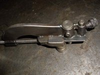
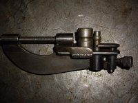
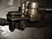
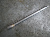
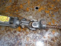
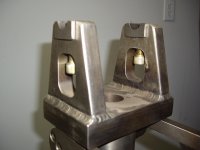
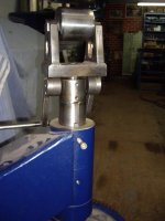
Well I guess you need access to a lathe to be able to make the rolling dies.I used 4140 material to make mine,the rest is just mild steel.I will be modifying the inner die by adding a twist handle a bit like a can opener to help drive it.The inner die has a groove in it to keep it from moving back and forth in the housing and an Allen screw threaded in the housing long enough to go into the groove.
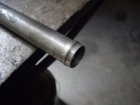
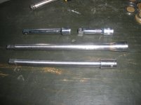
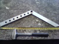
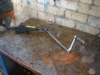
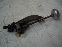
The plate with a shaft welded to it is a guide to keep the distance of the bump constant on the edge of the tube to be worked.
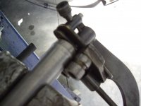
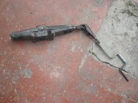
The outer two roller dies are held in place with shoulder bolts threaded into the sliding plate witch is a little like a hand holding onto the main body of the tool.This plate has a threaded rod going into a bushing that has a shoulder to bottom out and a tiny shoulder bolt to hold it on when unscrewing or backing off pressure.At the other end the threaded rod goes thou a threaded bushing that is welded to the body.And finally I machined an aluminum knob that is threaded and locktited to the threaded rod.
Not something I use every day but very handy when I make parts for Formula Fords or Vintage race cars.
If you end up making one,it would be nice to see it here.
Enjoy
")


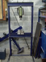
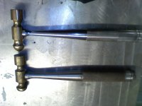
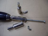
 The reason mine is mounted the way I did and a groove machined in the top wheel is so you can grab it with your hand and help drive it a little.Some times I abuse it and flatten some 3/16 steel plate.What do you use that 3rd attachment for
.jpg)
.jpg)
.jpg)


 to cut it open!