OP
DocsMachine
Well-known member
- Joined
- Sep 16, 2006
- Messages
- 1,848
One product I commonly make is a paintball gun barrel that takes inserts of different sizes. This helps the player match the bore of the barrel to the size of the paintball that day, and this aids accuracy and gas efficiency. There are, however, some markers out there that weren't designed with such features in mind, and in order to use a barrel like this, it needs a shallow "step" inside the bore, to retain the insert.
The issue here is that there's a common, off-the-shelf aluminum tubing that has an ideal bore, as supplied. I've been using it for years, and point in fact, I'm all but certain the manufacturer that invented this system, used the same stuff. The problem being that, for those barrels that need that "step", there's no easy way to add that, without threading, welding or turning from solid bar.
I've pondered this issue for some time, and with a little thought and some advice from the Internet At Large® I came up with a solution: Since the end with the step needs to be fully machined anyway, what if I swaged the end of the tube down ? Basically just squished it in a controlled manner to a smaller OD and ID, and then turned the features into it.
A fellow over on HSM posted a pic of a shop-made guillotine swage that I thought would work. I really need to get moving on these parts, if I'm going to do anything with them, so I took some time this morning to build my own version. TLR version? It works perfectly.
I started with a hunk of old I-beam out of the scrap piles...

That got ground, sanded and brushed down...

And then bandsawed into pieces.

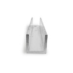
For guides, I dug two chunks of 1" hot-rolled out of the same pile, and slotted each one to fit the web of the I-beam.

A little bit of fine-tuning with the belt-grinder and a smidge o' TIG, and voila!

That goes into the mill and the operative bore... er, bored.

Bit of guesswork there: I wanted to reduce the bore by about .075", so the ID of the dies were cut to about .075" less than the OD of the tubing. The exact number was irrelevant, as long as there was enough material to turn it to the final dimension.
After a little deburring and smoothing, it was time to give it a try. I had some scrap barrels to try it on, so with a little bit of oil brushed on, I stuck the whole mess in the press and gave 'er a squish.

And that, actually, turned out just perfectly.

It's not an even squash, I may try going most of the way, turning the tube 90 degrees, and squishing the rest, but even still, that right there is 100% usable.
The bore ended up football shaped, .655" (down from the original nominal .750") across the die parting lines, and .675" vertically. The finished bore needs to be between .695" and maybe .705", so that's perfect.
I chucked it up to see how it turned back to round...

And it appears to have worked perfectly. I turned the bore back to .695", and it retains the insert perfectly.

You can see just a touch of eccentricity to the left there, but taking another 5 thou or so, and maybe turning the tube 90 degrees should solve that. Might add a couple short return springs to the swage help make that go a little quicker.
Nice little win to cap off what had been a bit of a tedious week.
Doc.
The issue here is that there's a common, off-the-shelf aluminum tubing that has an ideal bore, as supplied. I've been using it for years, and point in fact, I'm all but certain the manufacturer that invented this system, used the same stuff.
The problem being that, for those barrels that need that "step", there's no easy way to add that, without threading, welding or turning from solid bar.I've pondered this issue for some time, and with a little thought and some advice from the Internet At Large® I came up with a solution: Since the end with the step needs to be fully machined anyway, what if I swaged the end of the tube down ? Basically just squished it in a controlled manner to a smaller OD and ID, and then turned the features into it.
A fellow over on HSM posted a pic of a shop-made guillotine swage that I thought would work. I really need to get moving on these parts, if I'm going to do anything with them, so I took some time this morning to build my own version. TL
R version? It works perfectly. I started with a hunk of old I-beam out of the scrap piles...
That got ground, sanded and brushed down...
And then bandsawed into pieces.
For guides, I dug two chunks of 1" hot-rolled out of the same pile, and slotted each one to fit the web of the I-beam.
A little bit of fine-tuning with the belt-grinder and a smidge o' TIG, and voila!
That goes into the mill and the operative bore... er, bored.
Bit of guesswork there: I wanted to reduce the bore by about .075", so the ID of the dies were cut to about .075" less than the OD of the tubing. The exact number was irrelevant, as long as there was enough material to turn it to the final dimension.
After a little deburring and smoothing, it was time to give it a try. I had some scrap barrels to try it on, so with a little bit of oil brushed on, I stuck the whole mess in the press and gave 'er a squish.
And that, actually, turned out just perfectly.
It's not an even squash, I may try going most of the way, turning the tube 90 degrees, and squishing the rest, but even still, that right there is 100% usable.
The bore ended up football shaped, .655" (down from the original nominal .750") across the die parting lines, and .675" vertically. The finished bore needs to be between .695" and maybe .705", so that's perfect.
I chucked it up to see how it turned back to round...
And it appears to have worked perfectly. I turned the bore back to .695", and it retains the insert perfectly.
You can see just a touch of eccentricity to the left there, but taking another 5 thou or so, and maybe turning the tube 90 degrees should solve that. Might add a couple short return springs to the swage help make that go a little quicker.
Nice little win to cap off what had been a bit of a tedious week.
Doc.


 And might want to add a stiffener across the top of the pegboard!


.jpeg")