
Since your new ATS is now considered the main disconnect/panel, you will also need two ground rods spaced 6 ft or more apart and connect them to the new ATS with #6 Copper. New equipment has to meet the current code requirements. (You can still use the old ground rod for one of these.)
I was considering this, but wasn't sure it was required. What I am not sure about is the proper connection at the service. You say "connect them to the new ATS". The current bare copper is connected to the neutral in the meter base. If I add a ground rod I would run one continuous piece of new #6 copper to both rods.
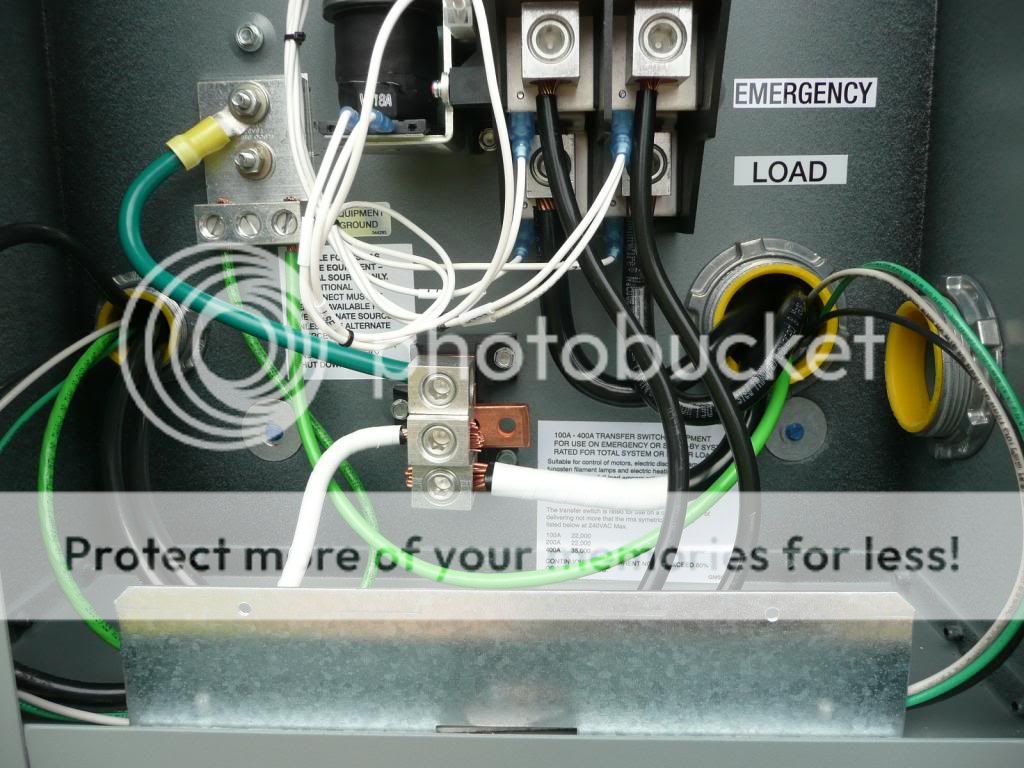
Yes loop the conductor through the first acorn clamp.Where should I terminate it in the service? The meter or the ATS? Terminate it in the ATS right next to the green bonding jumper on that ground block (not the neutral block.) Bring it out of the bottom of the ATS with a ½” romex clamp.
Since you only have a concentric KO on one end of that ****** between ATS and meter pan, you can use a bonding locknut on the ATS side - not the meter side.
Will do. Do I need any other bonding or grounding locknuts or bushings anywhere else? No, bonding is only for service equipment – in your case it is only: meter pan, ******, ATS.
Did you install a double locknut (back-back i.e. – interior/exterior) on the new ****** from ATS into the old panel? It needs to have this to meet code and be considered a grounding means for that ******.
I did not. I could not get one through the wall without opening up the hole in the brick all the way through. I only opened it up deep enough to make room for the rainproof hub on the back of the ATS. How important is it that the main panel be grounded via the ******? It will be grounded with a #6 copper via the 4 wire sub panel feed. That’s what I figured. You are right, the sub panel will be grounded with that #6, but one locknut isn’t meeting code. Your call on that! (FYI – the exterior locknut on the utility riser conduit into the meter pan is installed upside down – teeth need to bite into the meter pan enclosure.)
I saw that, but there is no way to correct it short of having the POCO kill the power at the pole so the meter base could be removed. Agreed – it was FYI only.
I also wanted to bring up that the interior side of the wall that the (oldmain) new sub panel is located on needs to be sheet-rocked for fire protection.
The rest of the room is paneling, as was the area around the main panel before I removed it for access. It will be recovered when I finish. FYI – paneling by itself has no fire rating.
The LB covers must remain accessible. Doesn’t matter if they contain splices.
I wasn't sure if they had to be accessible or not, since they do not contain any splices. But I planned to make a removable (mounted with screws) access plate for them anyway. If any of that wiring ever had to be changed/modified they would have to be opened up.
Too late to change the job to get rid of those - too much to backtrack on to eliminate.
What is the purpose of the ¾” T?
At the T the control cable between the generator and ATS will pass through, but the CAT 5E network cable will exit and continue in free air to the attic and on to my router. Before I pull that cable I will add a cable clamp to that opening, for strain relief and to seal up the conduit.
Your Cat 5 cable needs to be rated at least 300 volt to be in that conduit.
Your panel looks flush with the studs – it should be raised 3/8 - 1/2” for sheet-rocking.
Pictures can be deceiving, it is raised. OK good – nevermind!!
Once you have the old feed to the panel removed from the meter, ATS utility side fed from the meter, and before replacing meter, I suggest you do the following:
Label and remove all branch circuits,
Remove the panel entirely,
add a KO seal to the back of the panel opening from the old ****** – peen the ends over,
remove the old ****** from the meter pan and KO seal that opening,
seal the wall
replace the new ****** with a longer one (3/8 – ½” longer) and locknut
install the panel, locknut and bushing
Feed the panel from the ATS load side through the new ****** – identify neutral and ground wires with tape
One by one – re-install each branch circuit cable with proper connectors and staple each within 12” of panel
Remember the new grounding block(s) – neutrals and grounds are separated now
(You may want to provide a horizontal nailer above the panel first to give easy access to staple)
I had considered replacing the entire panel, but could not find a justification to do so. If it was smaller would be a reason, but it is already 200A. If I needed more circuit spaces would be a reason, but I have spaces left over. The existing panel should be fine – I wouldn’t replace it.I had not considered pulling it out just to seal the old opening to the meter. Also, it does not need to be repositioned to be flush with the finished wall, so would not need the longer ******. I realise that I will have it 90 percent removed because I am going to remove all the branch circuit wires to add the NM cable clamps. It is nailed in place, so those would be more difficult to remove than if it was screwed in. So the only reason to remove it would be to take out the ****** to the meter base, or to add the lock nut to the exterior of the ****** to the ATS (if necessary, see above). I planned to just seal both ends of that ******. Would that be good enough? If my house, I would do it. At least put duct seal in both ******* to keep out air flow/condensation out of enclosures.
If the nails are through the sides of the panel into the studs, you could take a sawzall and quickly cut the nails without concern of damage to the panel.I have a new ground bar for separating the neutrals and grounds.
I had not thought about adding a horizontal nailer above the panel, but I will. Thanks for the suggestion.
To your question about oxide inhibitor – I use it on all exterior lug connections, including removing the lug set screw and applying to those threads – prevents galling and allows for better torque applied onto the conductor instead of just torque between set screw and lug body.
I guess I need to look for oxide inhibitor listed for copper. All I have seen before says it is for aluminium. Most aluminum oxide inhibitors are also used for al–cu connections. I’m not saying to use on the cu conductor, but use it on the threads of the lugs. Sorry if I confused the point.
!!!!!!>>>>I missed this first pass through – you have 2 sets of thw conductors (not cables) run in the wall going into the panel. Those have to be either put in conduit or replaced with NM cable. That is just as bad as the romex splice 2 feet above the panel.<<<<<<!!!!!! Now is the time!
I was considering this, but wasn't sure it was required. What I am not sure about is the proper connection at the service. You say "connect them to the new ATS". The current bare copper is connected to the neutral in the meter base. If I add a ground rod I would run one continuous piece of new #6 copper to both rods.
Yes loop the conductor through the first acorn clamp.Where should I terminate it in the service? The meter or the ATS? Terminate it in the ATS right next to the green bonding jumper on that ground block (not the neutral block.) Bring it out of the bottom of the ATS with a ½” romex clamp.
Since you only have a concentric KO on one end of that ****** between ATS and meter pan, you can use a bonding locknut on the ATS side - not the meter side.
Will do. Do I need any other bonding or grounding locknuts or bushings anywhere else? No, bonding is only for service equipment – in your case it is only: meter pan, ******, ATS.
Did you install a double locknut (back-back i.e. – interior/exterior) on the new ****** from ATS into the old panel? It needs to have this to meet code and be considered a grounding means for that ******.
I did not. I could not get one through the wall without opening up the hole in the brick all the way through. I only opened it up deep enough to make room for the rainproof hub on the back of the ATS. How important is it that the main panel be grounded via the ******? It will be grounded with a #6 copper via the 4 wire sub panel feed. That’s what I figured. You are right, the sub panel will be grounded with that #6, but one locknut isn’t meeting code. Your call on that! (FYI – the exterior locknut on the utility riser conduit into the meter pan is installed upside down – teeth need to bite into the meter pan enclosure.)
I saw that, but there is no way to correct it short of having the POCO kill the power at the pole so the meter base could be removed. Agreed – it was FYI only.
I also wanted to bring up that the interior side of the wall that the (oldmain) new sub panel is located on needs to be sheet-rocked for fire protection.
The rest of the room is paneling, as was the area around the main panel before I removed it for access. It will be recovered when I finish. FYI – paneling by itself has no fire rating.
The LB covers must remain accessible. Doesn’t matter if they contain splices.
I wasn't sure if they had to be accessible or not, since they do not contain any splices. But I planned to make a removable (mounted with screws) access plate for them anyway. If any of that wiring ever had to be changed/modified they would have to be opened up.
Too late to change the job to get rid of those - too much to backtrack on to eliminate.
What is the purpose of the ¾” T?
At the T the control cable between the generator and ATS will pass through, but the CAT 5E network cable will exit and continue in free air to the attic and on to my router. Before I pull that cable I will add a cable clamp to that opening, for strain relief and to seal up the conduit.
Your Cat 5 cable needs to be rated at least 300 volt to be in that conduit.
Your panel looks flush with the studs – it should be raised 3/8 - 1/2” for sheet-rocking.
Pictures can be deceiving, it is raised. OK good – nevermind!!
Once you have the old feed to the panel removed from the meter, ATS utility side fed from the meter, and before replacing meter, I suggest you do the following:
Label and remove all branch circuits,
Remove the panel entirely,
add a KO seal to the back of the panel opening from the old ****** – peen the ends over,
remove the old ****** from the meter pan and KO seal that opening,
seal the wall
replace the new ****** with a longer one (3/8 – ½” longer) and locknut
install the panel, locknut and bushing
Feed the panel from the ATS load side through the new ****** – identify neutral and ground wires with tape
One by one – re-install each branch circuit cable with proper connectors and staple each within 12” of panel
Remember the new grounding block(s) – neutrals and grounds are separated now
(You may want to provide a horizontal nailer above the panel first to give easy access to staple)
I had considered replacing the entire panel, but could not find a justification to do so. If it was smaller would be a reason, but it is already 200A. If I needed more circuit spaces would be a reason, but I have spaces left over. The existing panel should be fine – I wouldn’t replace it.I had not considered pulling it out just to seal the old opening to the meter. Also, it does not need to be repositioned to be flush with the finished wall, so would not need the longer ******. I realise that I will have it 90 percent removed because I am going to remove all the branch circuit wires to add the NM cable clamps. It is nailed in place, so those would be more difficult to remove than if it was screwed in. So the only reason to remove it would be to take out the ****** to the meter base, or to add the lock nut to the exterior of the ****** to the ATS (if necessary, see above). I planned to just seal both ends of that ******. Would that be good enough? If my house, I would do it. At least put duct seal in both ******* to keep out air flow/condensation out of enclosures.
If the nails are through the sides of the panel into the studs, you could take a sawzall and quickly cut the nails without concern of damage to the panel.I have a new ground bar for separating the neutrals and grounds.
I had not thought about adding a horizontal nailer above the panel, but I will. Thanks for the suggestion.
To your question about oxide inhibitor – I use it on all exterior lug connections, including removing the lug set screw and applying to those threads – prevents galling and allows for better torque applied onto the conductor instead of just torque between set screw and lug body.
I guess I need to look for oxide inhibitor listed for copper. All I have seen before says it is for aluminium. Most aluminum oxide inhibitors are also used for al–cu connections. I’m not saying to use on the cu conductor, but use it on the threads of the lugs. Sorry if I confused the point.
!!!!!!>>>>I missed this first pass through – you have 2 sets of thw conductors (not cables) run in the wall going into the panel. Those have to be either put in conduit or replaced with NM cable. That is just as bad as the romex splice 2 feet above the panel.<<<<<<!!!!!! Now is the time!
 The other route is through the crawlspace, but that utility room where the breaker panel is has a concrete floor. That entire end of the house is either garage or that room. So to get to the crawlspace, I still have to start out in the attic. I am aware of the code violation, but haven't decided how to correct it, and am open to suggestions.


 I am confident I can take a shower during a power outage.