To avoid these ads, REGISTER NOW!

Is this a 15 amp outlet?

mechaniac86

Active member
Joined
Apr 27, 2015
Messages
27
Location
Lafayette, LA
So I've been adding outlets in my garage when I came across this...


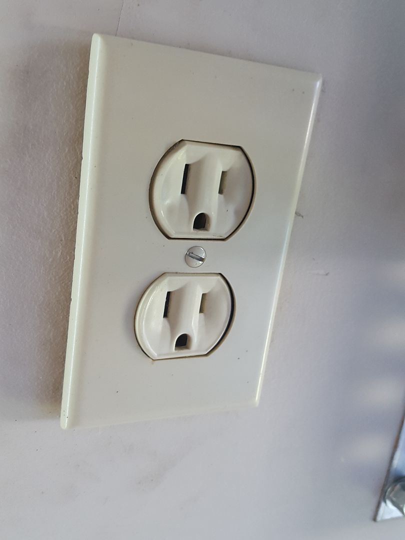
This is the outlet that my garage door is plugged into. It is on a 20 amp circuit and it has 12 ga Romex going to the receptacle. Everything I've read has said that the 20 amp outlets have the extra little cutout in the the slots. Do ALL 20 amp outlets have this extra little cutout? In other words, is the outlet shown above definitely a 15 amp outlet?

The house was built in 2009 if that's relevant.
 
To avoid these ads, REGISTER NOW!

aandpdan

Well-known member
Joined
Nov 12, 2009
Messages
849
Location
In between MA and PA
It's code compliant too. As long as there is more than a single receptacle, that counts as two, you're fine to use a 15 amp receptacle on a 20 amp circuit.

You won't find many tools/appliances with a 20 amp cord set.
 

theoldwizard1

Well-known member
Joined
Feb 22, 2011
Messages
43,138
Location
SE MI
Everything I've read has said that the 20 amp outlets have the extra little cutout in the the slots. Do ALL 20 amp outlets have this extra little cutout?
TRUE 20A receptacles do have have that extra notch.

In other words, is the outlet shown above definitely a 15 amp outlet?
Yeah, it is a 15A outlet. This one of the very few exceptions that NEC has, allowing a 15A duplex receptacle on a 20A circuit. Probably because there are SO FEW 20A appliances in existence !

That is probably a "builders grade" 15A duplex receptacle. A "standard" 20A duplex receptacle probably costs at least 5 times the cost of that one. Yes, they are better. 5 times better ?????
 
Last edited:

Stuff

Well-known member
Joined
Aug 31, 2013
Messages
572
If you look at the specs a 15 amp receptacle is rated for 20 amp feed-through. It doesn't prove anything but on another forum someone ripped apart the 15 and 20 amp versions of the same manufacturer's receptacle and found everything the same except for the T-slot.
 
OP
M

mechaniac86

Active member
Joined
Apr 27, 2015
Messages
27
Location
Lafayette, LA
Adding Outlets in Garage

Thanks everyone!

I just discovered another 15 amp outlet on the same circuit. It's a little counterintuitive that 20 amp (12 ga) wire is REQUIRED on 20 amp circuits, but 15 amp outlets are OK.

Why doesn't the same principle (overheating as I understand) not apply to the outlet?

I suppose at this point I can confess my first mistake in this project. I originally installed 14 ga wire.


Now that I've removed the 14 ga and purchased the correct 12-2 ga, I'm wondering what is the best way to connect 4 12 ga wires. Using the red wire nuts for the 3 #12 and 1 #14 was already pretty tight.

What's the best way to connect 4 #12 wires? Another one of my junction boxes is using these for #14 wire...


Will these work for #12 wire also? I've done a lot of reading and found a lot of people bashing these, but haven't heard of anyone experiencing an actual failure from using these. Really only a bunch of speculation as to the reliability and quality of the connection.

I also want to do a quad outlet in my ceiling to power my two extra shop lights also. I bought these 2 boxes. Which one do y'all think (if either) will work best?


The one on the left is 34 cu in. The one on the right is 38 cu in, but has round knockouts on the side instead of rectangular knockouts in the back.

Thanks again for all the help!
 
Last edited:

theoldwizard1

Well-known member
Joined
Feb 22, 2011
Messages
43,138
Location
SE MI
It doesn't prove anything but on another forum someone ripped apart the 15 and 20 amp versions of the same manufacturer's receptacle and found everything the same except for the T-slot.

Maybe if they are the same "grade", but a builders grade receptacle has different connection (back stabs) and at least a cheaper grade of plastic than a standard grade receptacle.

Then there are commercial/industrial and hospital (?) grade.
 

mm08822

Well-known member
Joined
Jan 13, 2012
Messages
5,901
Location
NJ
It's good that you are changing the existing box to a 2 gang. You had exceeded the 1 gang box fill considerably.
Each #12 conductor needs 2.25 cu in. All grounds count as 1 #12. Each recept counts as 2 #12's. So what ever box you use has to have at least 30 cu in (13 x 2.25).

Your spacing is tight with the joists and header relative to where the current box is. See if the wings on the old work box can swing to get into position to secure it properly.
 

theoldwizard1

Well-known member
Joined
Feb 22, 2011
Messages
43,138
Location
SE MI
Re: Adding Outlets in Garage

What's the best way to connect 4 #12 wires? Another one of my junction boxes is using these for #14 wire...
The "classic" way was to leave one lead extra long. Remove about 1" of insulation about 4-6" after the clamp inside the box, but leave the remaining insulation. Wrap that bared portion wire around one of the screws. What is left can be connected to the other wires with a nut. Also use the other screw as a connection point.

Better quality (commercial ?) receptacle have side clamps. You can put 2 wires under each side clamp.
 

Attachments

  • Capture.JPG
    Capture.JPG
    46.2 KB · Views: 351

dscheidt

Well-known member
Joined
Apr 26, 2017
Messages
2,890
That is probably a "builders grade" 15A duplex receptacle. A "standard" 20A duplex receptacle probably costs at least 5 times the cost of that one. Yes, they are better. 5 times better ?????

A spec grade outlet costs about $2. It's easily five better than a cheap 50 cent model. Easier to wire, will last many more insertion and removal cycles, and stands up to abuse better. Probably doesn't matter for a garage door opener outlet, but elsewhere in the garage it does, at least for most people around here.
 
OP
M

mechaniac86

Active member
Joined
Apr 27, 2015
Messages
27
Location
Lafayette, LA
Wow. So much great info! Thanks!

Ok see here's the schematic I've come up with for my plan. Sorry it is so crudely drawn, but hopefully y'all get the idea.


What do y'all think? The only issue I can think of is the orange highlighted box. I'm not sure how I can connect two 12 ga wires to the ground terminal on the original ceiling outlet.
 

theoldwizard1

Well-known member
Joined
Feb 22, 2011
Messages
43,138
Location
SE MI
It's good that you are changing the existing box to a 2 gang. You had exceeded the 1 gang box fill considerably.
Not that is right/to code, but I have seen it done.

So if you have 4 #12 coming in, but don't want 2 duplex receptacles (or 1 with a blank) showing on the outside what do you do ?

Install the 2 gang box further inset, cut a standard hole in the wallboard and then use a box extender ?
 

mm08822

Well-known member
Joined
Jan 13, 2012
Messages
5,901
Location
NJ
Wow. So much great info! Thanks!

Ok see here's the schematic I've come up with for my plan. Sorry it is so crudely drawn, but hopefully y'all get the idea.

What do y'all think? The only issue I can think of is the orange highlighted box. I'm not sure how I can connect two 12 ga wires to the ground terminal on the original ceiling outlet.

Loop the grd wire around the recept grd screws so there is only one wire under each screw. I would have that wire come from a pigtail, so the cable grounds are all spliced together independent of the recept grds.

Can that new single gang recept box easily be fed with two cables to eliminate one of the cables in the 2 gang box? (Just a thought)
 
OP
M

mechaniac86

Active member
Joined
Apr 27, 2015
Messages
27
Location
Lafayette, LA
Loop the grd wire around the recept grd screws so there is only one wire under each screw. I would have that wire come from a pigtail, so the cable grounds are all spliced together independent of the recept grds.

Is this what you mean?


Can that new single gang recept box easily be fed with two cables to eliminate one of the cables in the 2 gang box? (Just a thought)

Do you mean removing one of the cables that currently terminates in the ceiling receptacle and extending it to the new wall outlet? like this...


This gives me another orange highlighted box? Do I just mount another single gang box somewhere along the way to the new outlet to house the splices? Or do I just run a whole new Romex cable to wherever that other outlet/light is?
 
Last edited:

mm08822

Well-known member
Joined
Jan 13, 2012
Messages
5,901
Location
NJ
Is this what you mean?

see pic

Do you mean removing one of the cables that currently terminates in the ceiling receptacle and extending it to the new wall outlet?

Yes if it's easy to do. If not, don't rip the place apart to make it happen. Just trying to distribute box fill.

Screen Shot 10-13-17 at 12.39 AM.JPG
 

sberry

Banned
Joined
Jun 18, 2005
Messages
35,747
Location
Brethren, Michigan
I have installed 1000's of the 49 cent recepts, own hundreds of them and hav4e some in my shop see hi cycles and cant even remember the last one I replace due to wear or being faulty.
If you would have asked me 30 yrs ago I would have jumped on the wagon but after some experience I find it doesn't matter much if any.
 

nut_buster2017

Active member
Joined
Jun 6, 2017
Messages
35
Re: Adding Outlets in Garage

Thanks everyone!

I just discovered another 15 amp outlet on the same circuit. It's a little counterintuitive that 20 amp (12 ga) wire is REQUIRED on 20 amp circuits, but 15 amp outlets are OK.

Why doesn't the same principle (overheating as I understand) not apply to the outlet?

I suppose at this point I can confess my first mistake in this project. I originally installed 14 ga wire.


Now that I've removed the 14 ga and purchased the correct 12-2 ga, I'm wondering what is the best way to connect 4 12 ga wires. Using the red wire nuts for the 3 #12 and 1 #14 was already pretty tight.

What's the best way to connect 4 #12 wires? Another one of my junction boxes is using these for #14 wire...


Will these work for #12 wire also? I've done a lot of reading and found a lot of people bashing these, but haven't heard of anyone experiencing an actual failure from using these. Really only a bunch of speculation as to the reliability and quality of the connection.

I also want to do a quad outlet in my ceiling to power my two extra shop lights also. I bought these 2 boxes. Which one do y'all think (if either) will work best?


The one on the left is 34 cu in. The one on the right is 38 cu in, but has round knockouts on the side instead of rectangular knockouts in the back.

Thanks again for all the help!


It is likely my controls background speaking, but I am a huge fan of terminal strips
 
To avoid these ads, REGISTER NOW!

mm08822

Well-known member
Joined
Jan 13, 2012
Messages
5,901
Location
NJ
Thanks for the picture! So I'll have 5 bare ground wires twisted together in the same wire nut inside my 2-gang box?

5 #12's in a wirenut is no big deal. Buy the correct size and it's done. Sure you can buy greenies and all sorts of other bs, but a simple wirenut gets the job done.

This is one reason why I suggested you possibly divert a cable out of that 2 gang box and into the new recept box to eliminate some congestion in that ceiling box.
 

Muggzy

Well-known member
Joined
Jun 29, 2013
Messages
583
Location
Orange Co., NY
I don't know if I've missed it in the tread. I looked but no one seems to have addressed the logic of a 15a outlet on 20a line;
You can't plug a 20a device into a 15a outlet b/c there is no 't' slot on the outlet to accept the plug on a 20a appliance. So it's much harder to overload the line (wire). Yes, you could still plug in 2 15a loads, but the breaker is sized to protect the wire in the wall from overheating and starting a fire.

Sent from my Pixel XL using Tapatalk
 
Last edited:
OP
M

mechaniac86

Active member
Joined
Apr 27, 2015
Messages
27
Location
Lafayette, LA
It is likely my controls background speaking, but I am a huge fan of terminal strips

I use terminal strips in automotive applications all the time. I would love to do strips here as they keep things neat and organized, but I've never heard of it in a residential electrical application (though I have limited experience). Are wire strips code compliant?

5 #12's in a wirenut is no big deal. Buy the correct size and it's done. Sure you can buy greenies and all sorts of other bs, but a simple wirenut gets the job done.

This is one reason why I suggested you possibly divert a cable out of that 2 gang box and into the new recept box to eliminate some congestion in that ceiling box.

Got it. I just need a larger wire nut. Thanks!

I don't know if I've missed it in the tread. I looked but no one seems to have addressed the logic of a 15a outlet on 20a line;
You can't plug a 20a device into a 15a outlet b/c there it no 't' slot on the outlet to accept the plug on a 20a appliance. So it's much harder to overload the line (wire). Yes, you could still plug in 2 15a loads, but the breaker is sized to protect the wire in the wall from overheating and starting a fire.

Sent from my Pixel XL using Tapatalk

Great. Thanks for addressing that question!
 
OP
M

mechaniac86

Active member
Joined
Apr 27, 2015
Messages
27
Location
Lafayette, LA
Ok, two more concerns:

(1) The instructions that come with the GFCI outlets say that the a GFCI located in "position A" (see below) protects all the receptacles on the load side of the GFCI.

Does this mean I can return the many GFCI's that I bought and use the cheaper non-GFCI outlets, so long as I'm sure to install the non-GFCI outlets on the "load side" of the one GFCI outlet already installed in my garage?


(2) This concern involves securing the Romex cable to studs. This diagram here says that staples are required every 4.5 ft. and within 12 inches of the receptacle. My question is this: Is there a way to secure the Romex to the studs without removing large portions of my drywall?


6PTsocket

Well-known member
Joined
Mar 12, 2014
Messages
4,593
It's code compliant too. As long as there is more than a single receptacle, that counts as two, you're fine to use a 15 amp receptacle on a 20 amp circuit.

You won't find many tools/appliances with a 20 amp cord set.
You can say that again. I remember exactly one instance and that was fluorescent fixtures that had 20A plugs and receptacles so they could be daisy chained, and I have worked in a lot of places.

Sent from my SM-G900V using Tapatalk
 

6PTsocket

Well-known member
Joined
Mar 12, 2014
Messages
4,593
If you look at the specs a 15 amp receptacle is rated for 20 amp feed-through. It doesn't prove anything but on another forum someone ripped apart the 15 and 20 amp versions of the same manufacturer's receptacle and found everything the same except for the T-slot.
I ripped apart a bad 15 A. GFCI and found the 20 A. "T" slot behind the face plate. From the front, you could not tell. They charge more for a 20A. GFCI than a 15A.

Sent from my SM-G900V using Tapatalk
 

mm08822

Well-known member
Joined
Jan 13, 2012
Messages
5,901
Location
NJ
Ok, two more concerns:

(1) The instructions that come with the GFCI outlets say that the a GFCI located in "position A" (see below) protects all the receptacles on the load side of the GFCI.

Does this mean I can return the many GFCI's that I bought and use the cheaper non-GFCI outlets, so long as I'm sure to install the non-GFCI outlets on the "load side" of the one GFCI outlet already installed in my garage?


(2) This concern involves securing the Romex cable to studs. This diagram here says that staples are required every 4.5 ft. and within 12 inches of the receptacle. My question is this: Is there a way to secure the Romex to the studs without removing large portions of my drywall?


1)No pic found.
As long as the upstream gfci recept has the downstream recepts connected to the load terminals, then no additional gfci's are required downstream. All standard non-gfci recepts will have gfci protection.
You can return the excess.

2) Nm is required to be secured within 12" of a box and at open intervals of 4.5' applies to new work - where the walls/ceilings are open.
Old work (all surfaces closed up) permits fishing of cables from outlet to outlet without requiring staples.
 
OP
M

mechaniac86

Active member
Joined
Apr 27, 2015
Messages
27
Location
Lafayette, LA
1)No pic found.
As long as the upstream gfci recept has the downstream recepts connected to the load terminals, then no additional gfci's are required downstream. All standard non-gfci recepts will have gfci protection.
You can return the excess.

2) Nm is required to be secured within 12" of a box and at open intervals of 4.5' applies to new work - where the walls/ceilings are open.
Old work (all surfaces closed up) permits fishing of cables from outlet to outlet without requiring staples.

got it. Thanks!
 

6PTsocket

Well-known member
Joined
Mar 12, 2014
Messages
4,593
I have a GFCI outlet in my garage, fed from the breaker panel. From there it goes to an outlet on the front porch, bathroom 1, bathroom 2, the rear deck and ends in the basement. ONE GFCI for all that. amAll rhe GFCI wants to see is that the same amount of current that goes out in the hot, comes back on the neutral. If more than a few ma. has found another path to ground, it trips.

Sent from my SM-G900V using Tapatalk
 
OP
M

mechaniac86

Active member
Joined
Apr 27, 2015
Messages
27
Location
Lafayette, LA
Ok. I returned two of the GFCIs and I have decided to replace my GFCI outlet with a newer (white) one. My main concern is not mixing up the line and load wires. Here's what I'm working with. The top pic is the current GFCI in the garage wall. The second picture is the ceiling outlet for the garage door that I would like to expand to quad outlets. I just want to make sure that the additional ceiling and wall outlets are DOWNSTREAM from the GFCI.

Any suggestions before I start disconnecting anything? Do I just make sure to install the new GFCI exactly as the old one is installed?

Thanks again for all the help!


mm08822

Well-known member
Joined
Jan 13, 2012
Messages
5,901
Location
NJ
Not that is right/to code, but I have seen it done. It would be less of an issue if #14 was used instead of 12’s.

So if you have 4 #12 coming in, but don't want 2 duplex receptacles (or 1 with a blank) showing on the outside what do you do ?

Install the 2 gang box further inset, cut a standard hole in the wallboard and then use a box extender ?

I assume you are referring to a similar situation as the OP has – access from the attic. You would get a new work 4” sq x2-1/8” deep with a single gang mud ring (1/2" or 5/8") and plan the 1g sheetrock opening position with the box attached to the joist. Once the sheetrock opening is cut, lay the mud ring extension into the cutout and then secure the new work box to the joist.

You cannot use a 2 gang box set back behind the drywall and use a box extender for the desired 1g opening needed. How would you secure the box? How would you close off the other 1g opening? This would be a major hack job.

Best method is to plan the cable routing so you don’t exceed box fill. Box fills should be planned and not arrived at by accident. Daisy-chain where possible to minimize high # of cable entries into boxes.

If you don’t have access to one side of the wall/ceiling and you haven’t planned box fill properly or can’t make it work out due to constraints, then you are going to open the wall and put in the proper size box with a mud ring. Sheetrock and joint compound is only an emotional problem.
 

theoldwizard1

Well-known member
Joined
Feb 22, 2011
Messages
43,138
Location
SE MI
If you had purchased the upgraded receptacles with side clamps. you could get 4 wires under those 2 screws.

attachment.php
 

Radix2

Well-known member
Joined
May 28, 2014
Messages
1,853
Location
the thumb!, MI
If you had purchased the upgraded receptacles with side clamps. you could get 4 wires under those 2 screws.

This is bad advice.

It is extremely difficult to place an outlet into a box with 9! 12 ga wires attached...heck the normal 3 are bad enough.

Better to pigtail and if you want to be modern use the wago style connectors which allow the wires to lay much better than wire-nuts
 

850xpeps

Well-known member
Joined
Aug 6, 2017
Messages
1,365
This is bad advice.


It is extremely difficult to place an outlet into a box with 9! 12 ga wires attached...heck the normal 3 are bad enough.


Better to pigtail and if you want to be modern use the wago style connectors which allow the wires to lay much better than wire-nuts


Agree with this. One set of wires in and 1 set out is lots for a box that size. I wouldn’t be putting a plug there.
 
OP
M

mechaniac86

Active member
Joined
Apr 27, 2015
Messages
27
Location
Lafayette, LA
The receptacles I bought are the ones with the two terminals on each screw. The picture of the ceiling outlet that I posted earlier was the old outlet. These are the outlets I will be using for my quad outlet ceiling receptacle...


However, my plan is going to be to reduce the amount of wires in that box. One of the cable is feeding my back porch outlet. My plan is to extend the back porch cable and tie it into the new wall outlet in the garage. I have a few questions about this though.

Can I just add a new length of 12-2 cable connected with wire nuts? If so, would this junction need its own box? Can I house it in the garage door opener box located right next to my ceiling receptacle box (pictured directly below)?


Thanks again for all the help! My project is coming along nicely, except that I'm having to replace my attic latter right in the middle of all this!
 
OP
M

mechaniac86

Active member
Joined
Apr 27, 2015
Messages
27
Location
Lafayette, LA
Out of curiosity, I followed the cable to their destination to see if the GFI was really the first device on the circuit from the breaker. It was not. The line from breaker goes straight to garage ceiling outlet. The wall outlet in the garage is fed from the ceiling outlet, then goes on to feed the back porch outlet.

Is it a problem that my garage ceiling outlets are not GFI-protected, or does it matter? It wouldn't be very difficult to install the GFI in the ceiling instead of the wall so that it would be the first device on this circuit.


mm08822

Well-known member
Joined
Jan 13, 2012
Messages
5,901
Location
NJ
Out of curiosity, I followed the cable to their destination to see if the GFI was really the first device on the circuit from the breaker. It was not. The line from breaker goes straight to garage ceiling outlet. The wall outlet in the garage is fed from the ceiling outlet, then goes on to feed the back porch outlet.

Is it a problem that my garage ceiling outlets are not GFI-protected, or does it matter? It wouldn't be very difficult to install the GFI in the ceiling instead of the wall so that it would be the first device on this circuit.
http://www.jensonusa.com/Park-Tool-CG-23-Chain-Gang-System.jpg[/IMG][/URL]


Depending upon year of construction, garage ceiling gfci protection was not required. I would not bother now putting the garage door recepts on it.

Also a gfci located in the ceiling is not considered readily accessable.
Your ckt as you drew it is fine were the gfci's are located. Just put the laundry recept on on a gfci.
 

arkieguide

Well-known member
Joined
Aug 10, 2017
Messages
50
I don't know if I've missed it in the tread. I looked but no one seems to have addressed the logic of a 15a outlet on 20a line;
You can't plug a 20a device into a 15a outlet b/c there is no 't' slot on the outlet to accept the plug on a 20a appliance. So it's much harder to overload the line (wire). Yes, you could still plug in 2 15a loads, but the breaker is sized to protect the wire in the wall from overheating and starting a fire.

Sent from my Pixel XL using Tapatalk

From reading your input and that of others - it may be time to snag a friend that is an electrician and for a 6 pac. have him come over and direct you. As an master electrician for many years I never mind helping a friend out of A dangerous situation.:lol_hitti
 

sberry

Banned
Joined
Jun 18, 2005
Messages
35,747
Location
Brethren, Michigan
So it's much harder to overload the line (wire).
That is not why its always done. Many/most recept circuits are 20A and the wire don't know the difference. 20A is often used on tools where we want to be sure its not going to bother something else on a general circuit, its to force the use of a dedicated.
Think about this. There is a general in a science lab in a school. The instructors set it up for the night with sensitive equipment, same for computers etc and then the cleaning lady comes along with the vacuum and trips it up. Maybe she knows where the breaker is, maybe not but it fuggs up this general and who knows what. This is why some of this equipment comes 20A end, not always 20A cord. I see a vac at the school, 16 wire cord, 20A end someone put on it which the cleaner has twisted to fit 15,, ha.
Simply we put a 20 recept anywhere we would be able to tolerate a trip or on a dedicated circuit even.
 
Last edited:

Muggzy

Well-known member
Joined
Jun 29, 2013
Messages
583
Location
Orange Co., NY
That is not why its always done. Many/most recept circuits are 20A and the wire don't know the difference. 20A is often used on tools where we want to be sure its not going to bother something else on a general circuit, its to force the use of a dedicated.
Think about this. There is a general in a science lab in a school. The instructors set it up for the night with sensitive equipment, same for computers etc and then the cleaning lady comes along with the vacuum and trips it up. Maybe she knows where the breaker is, maybe not but it fuggs up this general and who knows what. This is why some of this equipment comes 20A end, not always 20A cord. I see a vac at the school, 16 wire cord, 20A end someone put on it which the cleaner has twisted to fit 15,, ha.
Simply we put a 20 recept anywhere we would be able to tolerate a trip or on a dedicated circuit even.
There are several good reasons to do it. I just shared a basic one for the OPs benefit. Unfortunately, contractors around here (and probably most everywhere) run 14 GA wire off of 15a breakers to 15 Amp outlets and that's it. The 20a breakers & outlets aren't appreciably more expensive, but the extra copper hurts their bottom line. So unless someone specs it, you get bare minimum.

Sent from my Pixel XL using Tapatalk
 
To avoid these ads, REGISTER NOW!
Top Bottom