
You are using an out of date browser. It may not display this or other websites correctly.
You should upgrade or use an alternative browser.
You should upgrade or use an alternative browser.
MP&C Shop Projects
- Thread starter MP&C
- Start date
Robert......Is there a particular reason that you used a large radius on the corners of the patch panel instead of just using a square corner? I should rephrase that as I know that there is a reason, but can you explain it to this dummy!!!!
Not to put words into Robert's mouth, but sharp corners always increase stresses.
What stresses, you ask? It's just a sheetmetal patch panel?
But when you weld it in, the molten steel then cools. As it cools, it contracts. As it contracts, that is 'pulling' the metal. Stress.
So the sharp corner increased the stress, and also increased the tendancy of the metal to move (warp, pull, etc) in all sorts of directions. Which makes one's life more difficult in trying to 'persuade' the metal back into the desired shape and position.
Curves are good.

e-tek
Well-known member
Robert - on your cart below, did you wire the 4x120V box together/from the 220V welder plug? If so, can you - aor anyone - tell me how to do that? I'd like to put the same set-up on my cart.
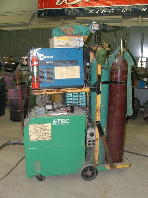
The power comes from the 220v 50a cord, hardwired to the upper box's outlet and the lower welder. The upper welder plugs in, and also gives you the option of using same outlet for the 220 spot welder. I believe I tapped one 120v outlet off of the A leg and one off the B leg, the returns tied to ground, just as the 220v plug uses. Gives you convenient outlets for the grinders where you're welding...


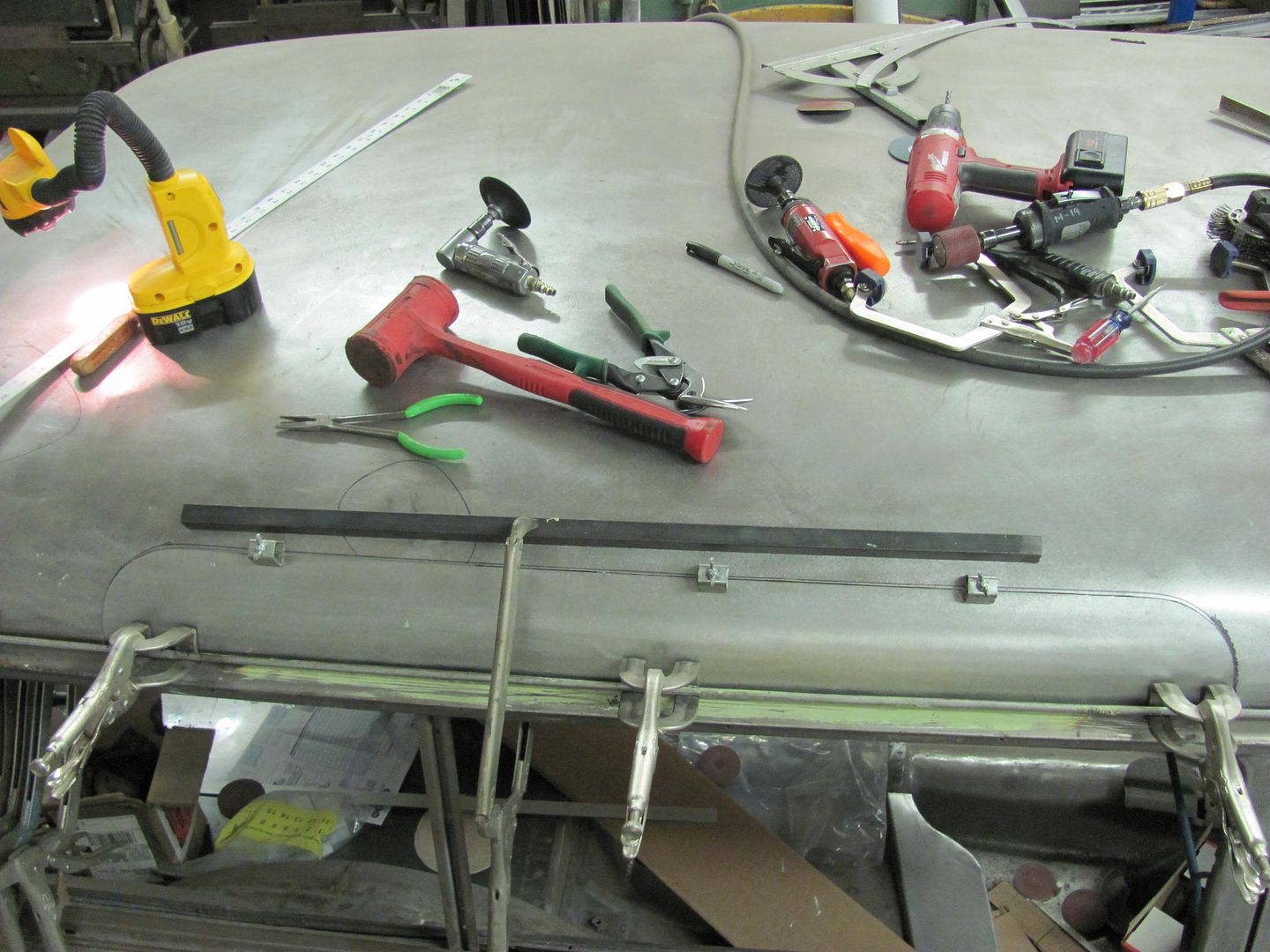
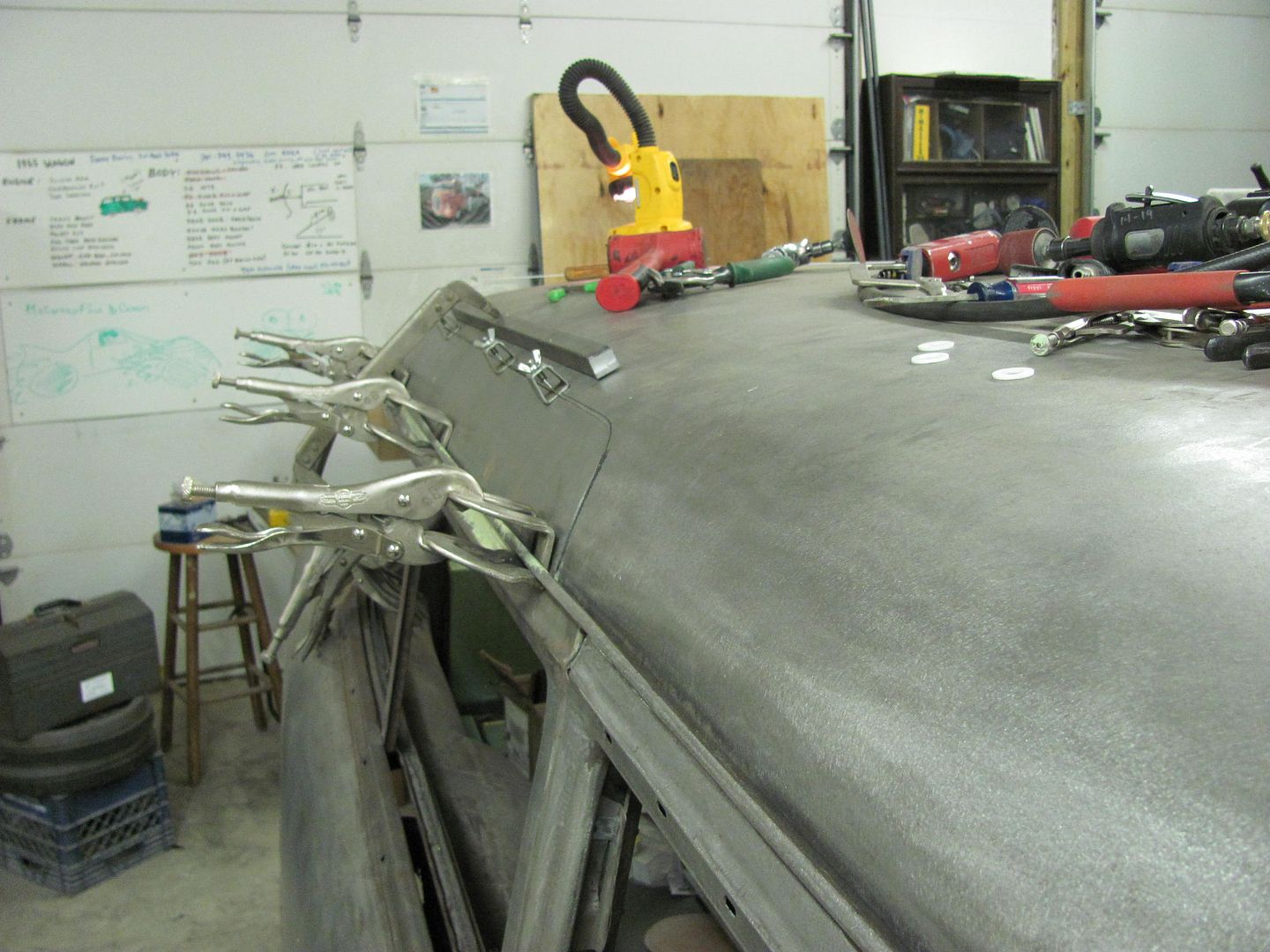
Continuing with the dissecting of the roof.....
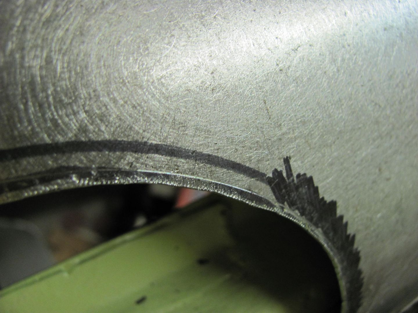
When I got into the section with the old roof, it was difficult to see the spot welds (for drilling) down inside the drip rail. The underside was more accommodating, so the face of the drip rail was marked with the sharpie to use as a reference while drilling...
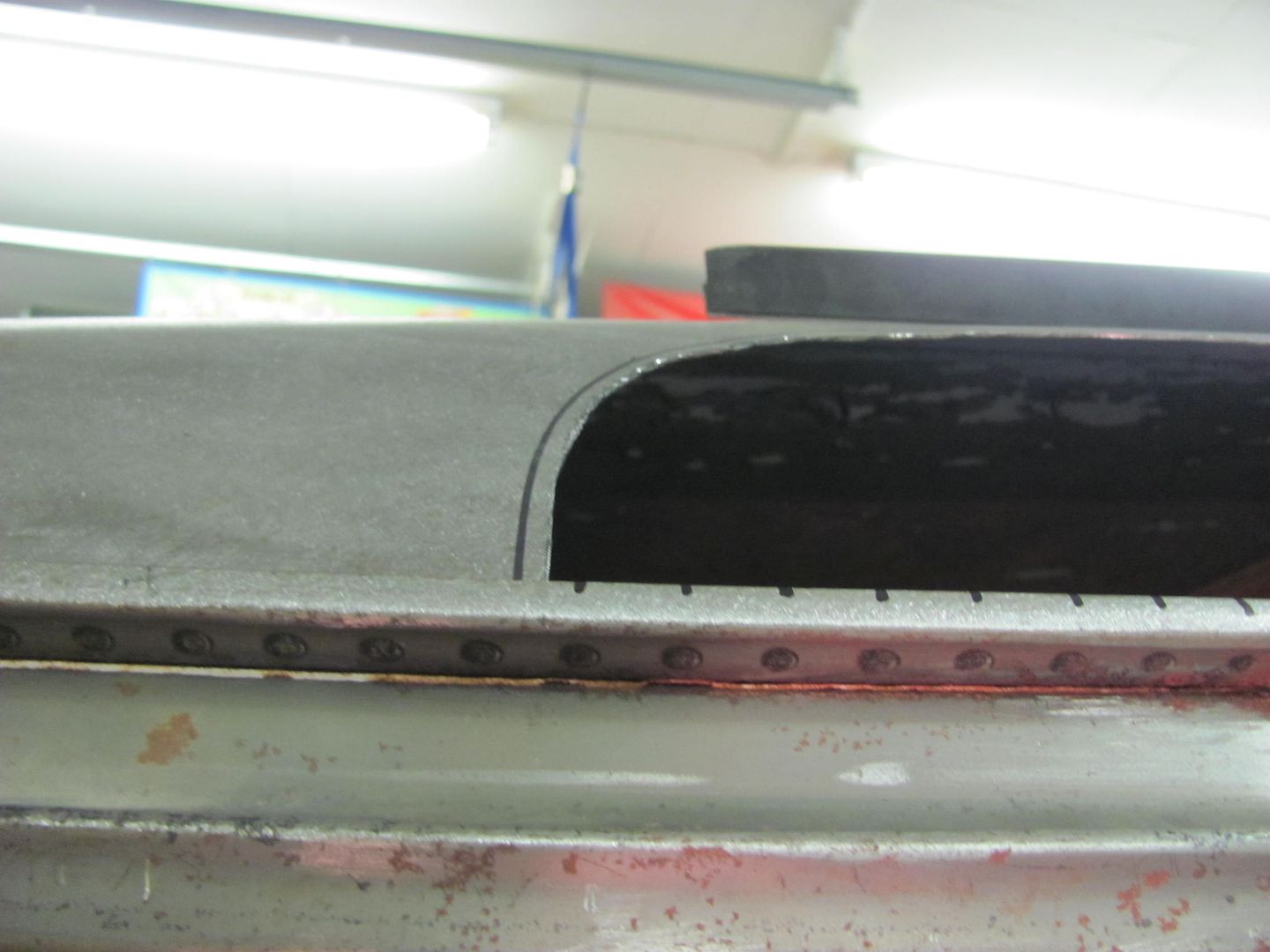
The lower corners of the opening were trimmed to size so that the roof patch could be clamped down into the drip rail. This will help to get more accurate markings on the roof skin for trimming the rest of the opening.
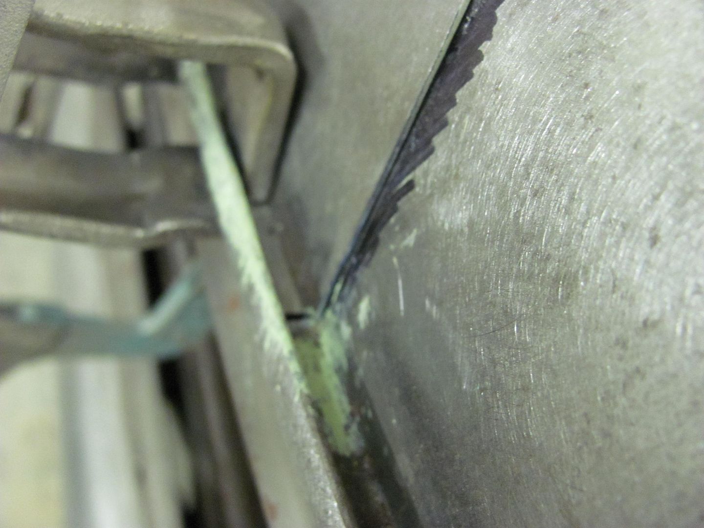
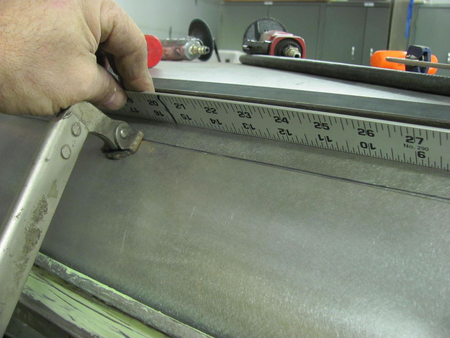
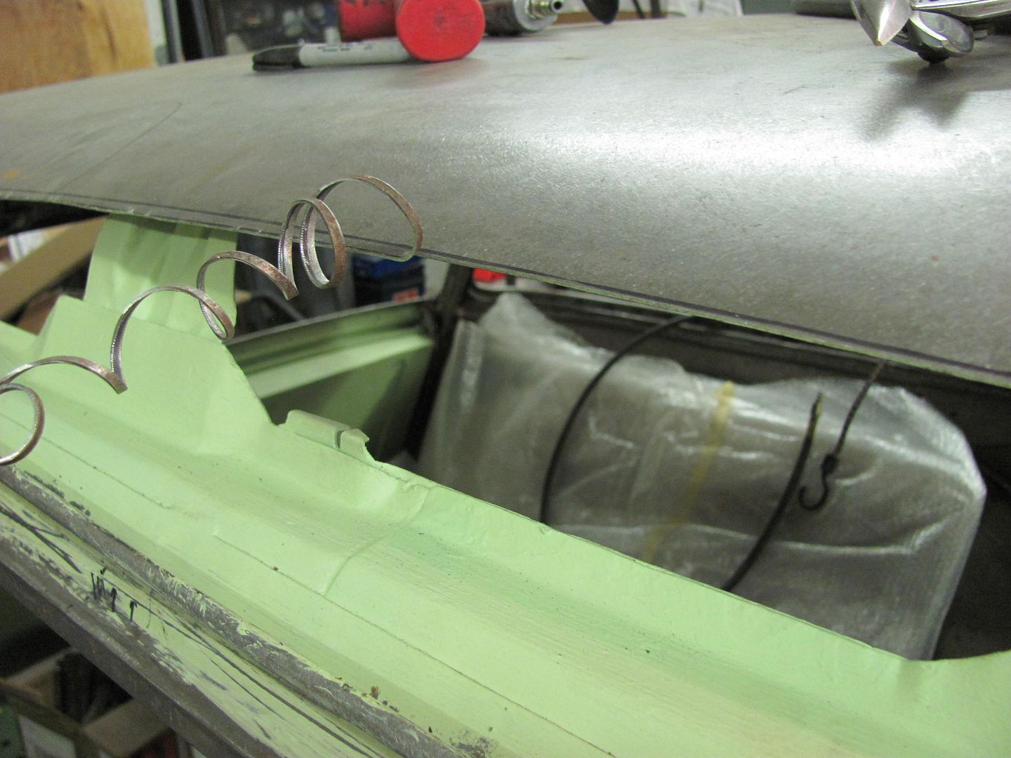
C-Clamp vise grips added to secure the overlapped panels for marking, then a straightedge used to read the crown of the roof to insure there were no dips or puckers along the top of the joint....
My favorite scribe, a local auction purchase...
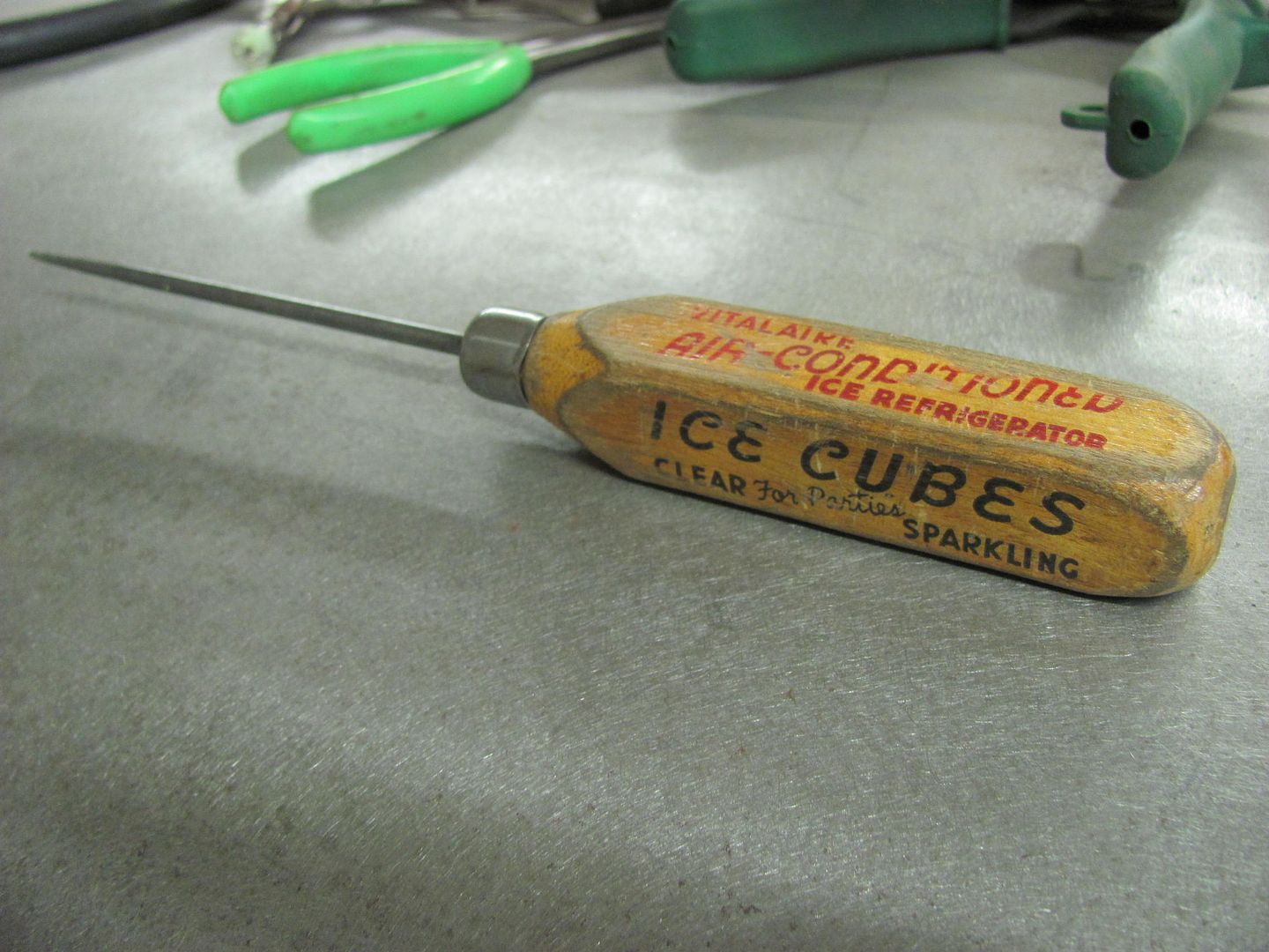
Scribing the roof panel
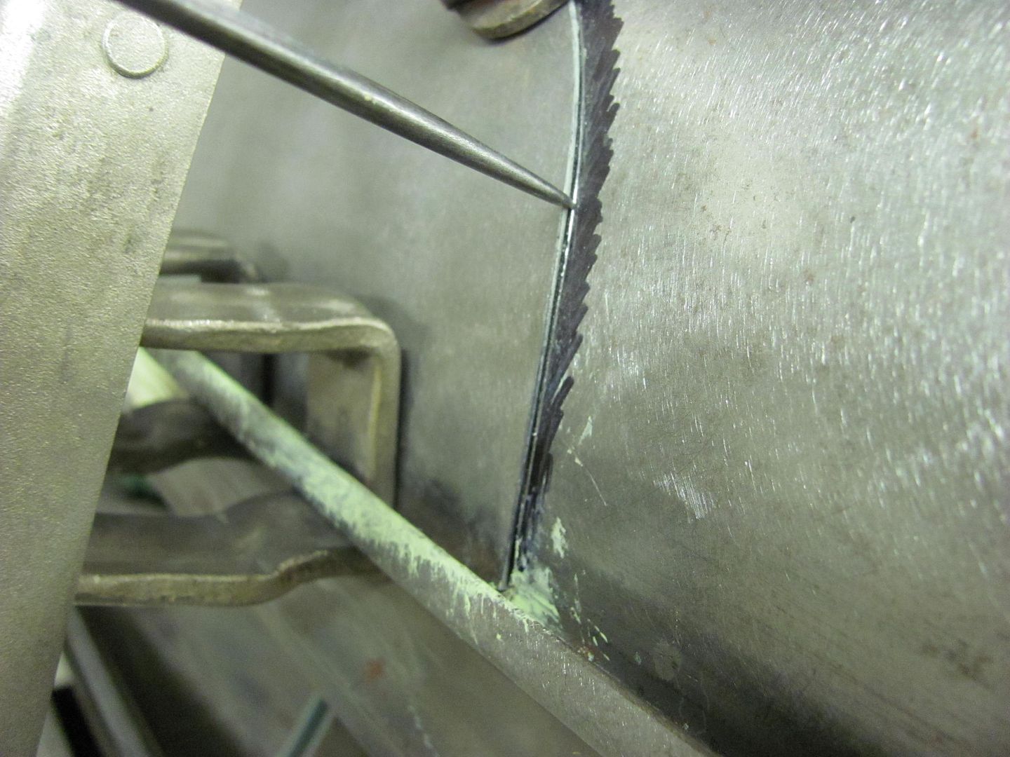
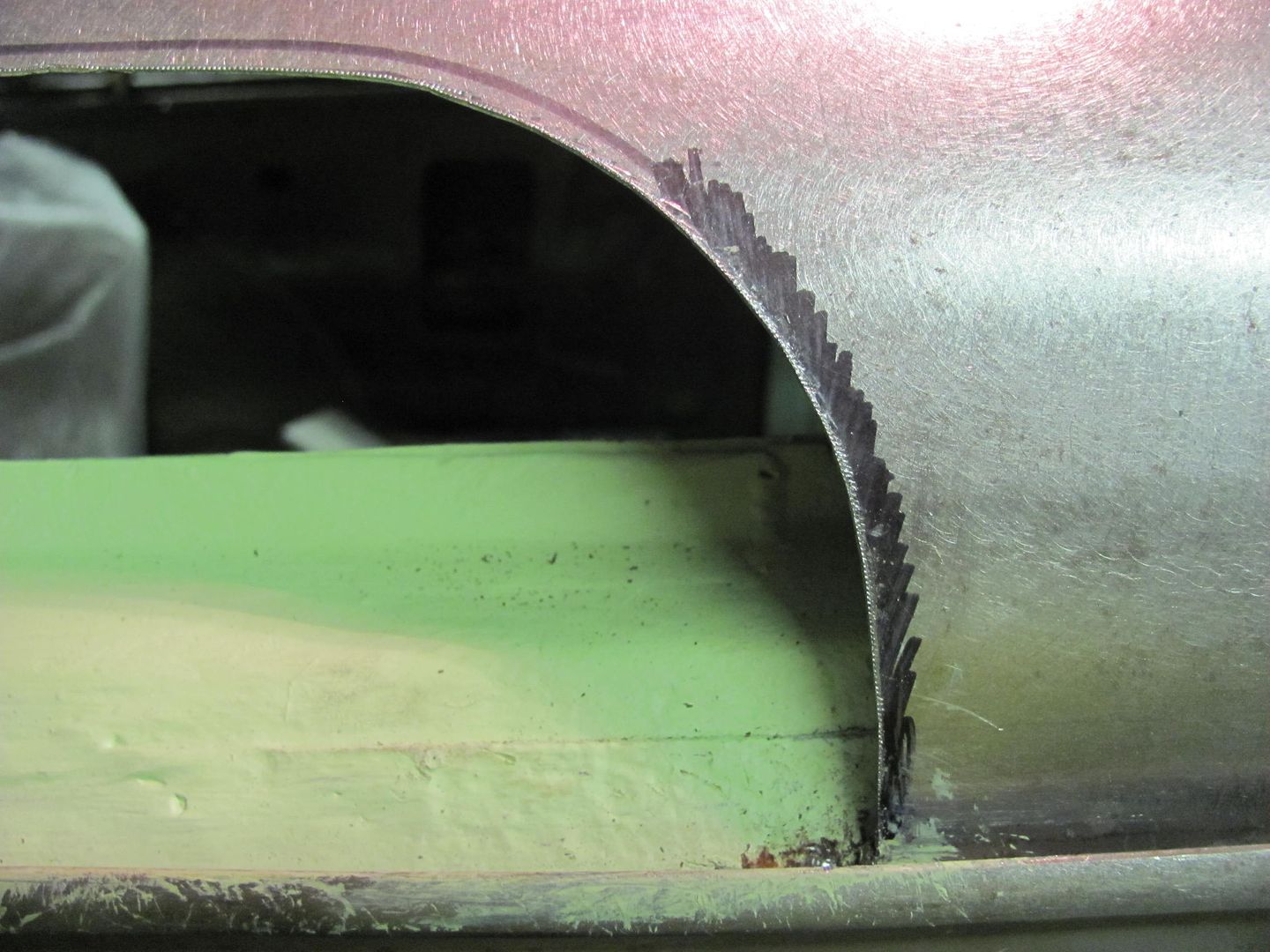
Not much to spare! Trimmed the opening with some offset snips...
Corners touched up with a 1-1/2" drum sander
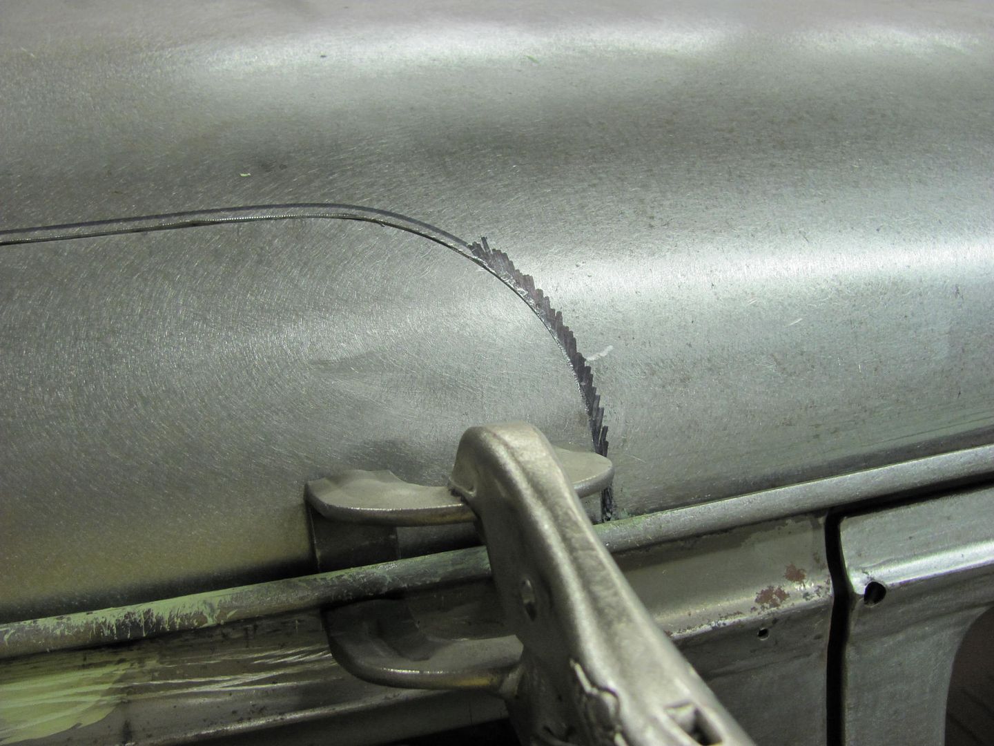
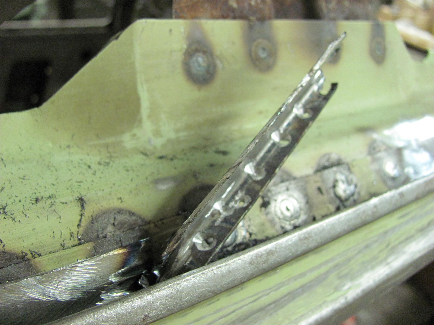
Clamped in place to hold the shape while we wait for the .023 ER70S-7 to come in. Note the **** weld clamps will be removed at welding for a tight fit-up.
When I got into the section with the old roof, it was difficult to see the spot welds (for drilling) down inside the drip rail. The underside was more accommodating, so the face of the drip rail was marked with the sharpie to use as a reference while drilling...
The lower corners of the opening were trimmed to size so that the roof patch could be clamped down into the drip rail. This will help to get more accurate markings on the roof skin for trimming the rest of the opening.
C-Clamp vise grips added to secure the overlapped panels for marking, then a straightedge used to read the crown of the roof to insure there were no dips or puckers along the top of the joint....
My favorite scribe, a local auction purchase...
Scribing the roof panel
Not much to spare! Trimmed the opening with some offset snips...
Corners touched up with a 1-1/2" drum sander
Clamped in place to hold the shape while we wait for the .023 ER70S-7 to come in. Note the **** weld clamps will be removed at welding for a tight fit-up.
Kevin54
MEMBER EMERITUS
Not to put words into Robert's mouth, but sharp corners always increase stresses.
What stresses, you ask? It's just a sheetmetal patch panel?
But when you weld it in, the molten steel then cools. As it cools, it contracts. As it contracts, that is 'pulling' the metal. Stress.
So the sharp corner increased the stress, and also increased the tendancy of the metal to move (warp, pull, etc) in all sorts of directions. Which makes one's life more difficult in trying to 'persuade' the metal back into the desired shape and position.
Curves are good.
Moonrise...thank you very much for that explanation

Kevin54
MEMBER EMERITUS
Robert.....I know that a lot of people use the welding clamps as you show in this pic. But you say that you never use them. What is the reason of not using them? By that I mean, does it take too much weld to fill the gap and penetration would be a hit and miss thing because of the gap, or with the panels up tight, do you get better weld penetration and a more secure seam?
I wish you would do a weld tutorial. I posted one video clip I found, but if possible, do you think you could do one to show the right way and wrong ways to weld?
Just like myself, I have a Lincoln Pro-Mig 135 with gas, but it is a 110v welder. I'm never going to be welding anything heavy, but like with mine, I think it will get me by on sheetmetal, or at least I hope it will.
I want to be able to set it correctly and not screw up my patch panels on my bedside when I go to put them in. But I also don't want the welds to look like a bunch of pigeon **** sitting on top of the metal.
I know that you talk about planishing the welds, but on something like a patch panel on the bedside, there is no back access to get a dollie in there to back up any hammering. With that, I know that I will need good penetration so I have enough to grind off on the frontside. And I don't want to use a ton of bondo to finish things off. Mud has it's place, and the less used the better.
So if you could post up a tutorial sometime, that would be great. I know what I want things to look like, but I just need to know how to get there.
Show us 'Ole Wise One!!!!!
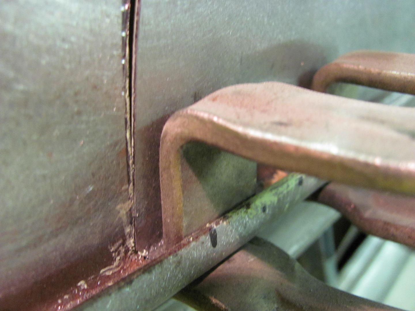
Kevin, more than anything, panel movement. You have enough issues to deal with considering any shrinking that occurs from the welding process. Leaving a gap only allows more panel movement. Place that weld in the middle of a low crown panel (roof, hood, etc) and any extra movement is only going to assist in losing crown and resulting in a loose oil can. Now place that weld joint next to a door jamb and you are risking altering the door gap's consistency. Here is a repair that came in the shop, the owner's first attempt shows how too much heat from filling in gaps has pulled the door/rocker to fender gap, for much inconsistency.
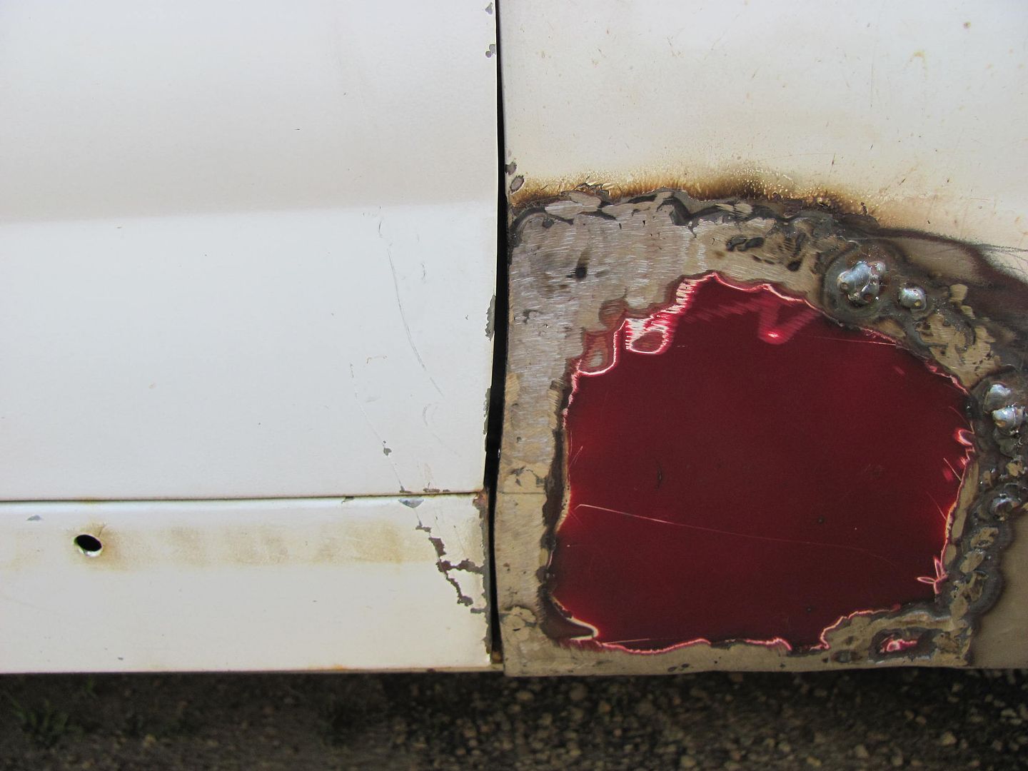
For a repair like this, my choice is to make the rear fender edge as part of the patch, to limit the number of vertical welds (and thus shrinking) and also to keep the weld joint from behind a fender brace, where ever possible, to allow access for planishing. But by butting the panels together tightly, you eliminate panel movement from the equation, and then shrinking effects are the only issue to deal with.
I like the idea of showing some welding tutorials, we have quite a few new welder owners that have been posting, it may help out with any sheet metal repairs as it is definitely a different animal than welding thicker plate. I'll have to fit something in here in the near future.
b-body-bob
Well-known member
Consider this my vote for a MP&C welding tutorial.
raskal
Well-known member
Kevin, more than anything, panel movement.
what do you think about starting with a flange on the repair panel (obviously not a door edge, etc.)
eg: http://www.harborfreight.com/air-punch-flange-tool-1110.html
that would make burn-through less of an issue (for people who can't weld like me).
Kevin54
MEMBER EMERITUS
what do you think about starting with a flange on the repair panel (obviously not a door edge, etc.)
eg: http://www.harborfreight.com/air-punch-flange-tool-1110.html
that would make burn-through less of an issue (for people who can't weld like me).
I have a flange tool like that, but from everything that I have read, a flange can lead to more rust because you have voids in the metal that would allow moisture to get trapped in between. And even though you could weld the front, and weld the back, there would still be a void between the two surfaces. I don't know how true it is, but I would like to know also, especially from an expert on it.
So Robert....if you would do a tutorial, then I'm going to have to get some scrap metal to follow along I guess. For something like my Dodge replacement patch panels, the material is .047 thick which is equivalent to 18 gage. I'll need to run a couple towns over to get some metal, which I can do that tomorrow. I have a shear that I can shear things up.
I'm looking forward to a tutorial from and expert. Once I get some material to practice on, then I'll wait until you have something together .
One question I do have though.....my welder. Is it capable of doing the welding that I see coming from you? I surely hope so, because I would hate to have to buy another welder at this stage in the game.
what do you think about starting with a flange on the repair panel (obviously not a door edge, etc.)
eg: http://www.harborfreight.com/air-punch-flange-tool-1110.html
that would make burn-through less of an issue (for people who can't weld like me).
I twitch every time someone mentions it. Sure, it can be a crutch for someone who is just learning to weld, but you are adding rust issues, as Kevin mentioned, regardless of how well you may seal something. The next issue is that the single panel thickness on one side of the weld expands faster in sunlight than two panel thicknesses on the other side. So regardless of the filler and paint covering it, the repeated differing expansion and contractions will leave a ghost line in your paint finish. Just like a wart on the end of a nose, everyone will see it and know exactly how the repair was done. IMO is detracts from the value of the car as it is not the correct way to repair. Save the money and hopefully when we're done you won't have any issues **** welding. Then you hear guys saying it's OK to use on floor pans as nobody will see them. Again, I disagree as this is the perfect scenario to practice **** welding to hone your skills, so when you are on a panel that really matters, you feel more comfortable doing it.
For those who try to weld cold to limit panel warping, that's the wrong approach as well. You'll need to leave the majority of the weld to maintain any strength at all, but with lack of weld penetration, the welds are subject to failure from vibration regardless. Leaving the weld in place sitting high on top of the panel and covering with filler makes for the same risk factors as above. The weld is going to have a slower expansion rate than the surrounding sheet metal and you are risking a ghost line in the paint finish, if the cold weld joint doesn't get you first when it fails. Full penetration welds should be the primary goal, first and foremost.
A lot of your success will come from panel fitment to get rid of gaps. Just as I showed in the post above for fitting the roof panel, make the patch, cut the hole smaller than needed, get the patch fitted, scribe and cut accurately with good quality snips (look elsewhere than HF, please) and trim the opening to size. Also, my suggestion for anyone practicing on the bench is to tack the two sides together, then get it off the bench. I span the piece across the open jaws of my vise to simulate a body panel in free air, as it is on the car. If you're going to practice, match the real situation as much as possible.
One question I do have though.....my welder. Is it capable of doing the welding that I see coming from you? I surely hope so, because I would hate to have to buy another welder at this stage in the game.
Kevin, please sell the flanger at your next yard sale... It will be worth much more before the tutorial comes out.. afterwards it will be worthless except as a glorified hole puncher

18ga steel typically uses between 70 and 80 amps, a bit more using my method, but well within the 140a welders that most hobbyists get from the box stores. As long as you have shielding gas option on it, you should have good results. I would also mention for anyone getting ready to buy wire, look for either EZ-Grind or ER70S-7 if you're doing sheet metal. As I'll show in the forthcoming tutorial, you'll be glad you did.
Last edited:
b-body-bob
Well-known member
Another point on flanging is if you warp it, good luck getting it straightened back out with the double thickness.
I've got a Lincoln 140 and have had good luck **** welding patches into my floor and trunk and plug welding a new jamb in. I don't have confidence in my **** welding ability to fix something that's not covered up though, so am looking forward to the upcoming tutorial thread.
I've got a Lincoln 140 and have had good luck **** welding patches into my floor and trunk and plug welding a new jamb in. I don't have confidence in my **** welding ability to fix something that's not covered up though, so am looking forward to the upcoming tutorial thread.
Zeke
Well-known member
I find the clamps to be of good use while tacking up. If you tack away from and in between the clamps the patch snugs up nicely to your scribe line. Of course you have to plan for this so clamping an entire patch at once might be a mistake. Depends on the patch and seldom are there any 2 alike. As you tack up the panel you remove the clamps, align the next place to be tacked and so on until you're in the stitching mode. It takes a lot of time and patience.
Not trying to usurp MP&C's posts or technique. Everything he says is right on.
Not trying to usurp MP&C's posts or technique. Everything he says is right on.
e-tek
Well-known member
Gives you convenient outlets for the grinders where you're welding...
Exactly what I was thinking - Thanks!
Moonrise...thank you very much for that explanation
Kevin, more than anything, panel movement.
Funny how many answers there are for every questions! Aside from Moon and Roberts answers, the reason I use curves is more to avoid the extra heat and weld build-up by welding in a corner.
what do you think about starting with a flange
I twitch every time someone mentions (using a flange).
I KNEW you'd say/feel that!!
TimeWarpF100
Well-known member
Robert, If I had 25% of your talent I could throw what I have in the trash . .
TimeWarpF100
Well-known member
My regret is that we live so far apart. All those nice Fords you get to work on, and your eye for detail, I'd be bugging you to combine forces..
Open 1.5 acre lot next door!
I just shut the garage door as getting a bit warm. 75+ deg out today!
Our winter came on a Tuesday afternoon this year. A couple clouds rolled in had a few drops of rain then it got nice again!
I just checked and temp has DROPPED down to 71 deg
Been searching for years to find a rusty veh here, only ones avail are the ones I see from MN
Last edited:
1971gsfan
Well-known member
Robert
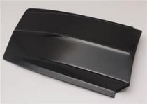
This is off topic but it is metal shaping Do you think I could make or shape this metal hood like the fiberglass one. I like the look of the raised cowl hood but would prefer it to be metal. I don't know if I would have to add metal or if it will stretch that far. Would I cut then bend up then weld in the metal where it is raised up or is there a better way to achieve this hopefully the pics show what I want first pic is the fiberglass end result wanted. second pic is the beginning metal hood like the ones I have now.
Thanks for any suggestions and as always I love your work. I read this thread from the beginning for the 4th time last night
This is off topic but it is metal shaping
Do you think I could make or shape this metal hood like the fiberglass one. I like the look of the raised cowl hood but would prefer it to be metal. I don't know if I would have to add metal or if it will stretch that far. Would I cut then bend up then weld in the metal where it is raised up or is there a better way to achieve this hopefully the pics show what I want first pic is the fiberglass end result wanted. second pic is the beginning metal hood like the ones I have now.Thanks for any suggestions and as always I love your work. I read this thread from the beginning for the 4th time last night
Attachments

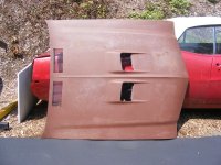
In short, the biggest challenge will be to get the opening correct for the grilles? that go in the holes. You will need blocking hammers to get that much stretch, perhaps a hammer form and some chasing tools. Here is a video by Peter Tommasini, one of the premiere metalshapers around. It highlights the use of blocking hammers for stretching and shows how he turns a flat sheet into what could pass for a factory direct replacement quarter.
He does have more in depth videos covering the complete process.
He does have more in depth videos covering the complete process.
Kevin54
MEMBER EMERITUS
Those openings look darn near like side vents on an older Mustang.
1971gsfan
Well-known member
In short, the biggest challenge will be to get the opening correct for the grilles? that go in the holes. You will need blocking hammers to get that much stretch, perhaps a hammer form and some chasing tools. Here is a video by Peter Tommasini, one of the premiere metalshapers around. It highlights the use of blocking hammers for stretching and shows how he turns a flat sheet into what could pass for a factory direct replacement quarter.
Cool video thanks
I was thinking I could start with the hood I have, cut the skin in the center(parallel with the back edge 6 inches or so in) work up the sides and front to the height I want. Then bend a piece in the new shape, weld it to the raised panel to get it back to the rear edge if that makes sense. seems like it would work if it will stretch that far. any suggestions are appreciated
The height of those hood scoops are not that tall, I think they could be formed without any welding, but it would not be for the faint of heart. Peter has in depth videos showing the processes he used on the quarter panel. I haven't ordered them yet, but have heard nothing but positive. I would think these videos or even a couple of metal shaping workshops under your belt first would be advisable, especially if you're real fond of that hood. I'd find a different one in not so nice shape, or not even from same car, to practice with to insure the process will work, and your skills will accommodate.
1971gsfan
Well-known member
Robert
I'm not explaining myself very well, wish I could draw on here. The whole center of the hood will be raised up. I wouldn't mess with the scoops at all. The center scoop section would be raised like a cowl induction hood. If I could explain it better it would make sense. With your talent (and Tools ) you could easily do what I'm saying and I feel I can do it after practicing a little on some metal I have. What I'm talking about is along the lines of removing the "bird" from the wagon hood.
Here are better pictures of what I want to accomplish This hood is fiberglass and shows the general idea. The last pic is the stock version I have. Note the center section height difference when you click on the thumbnails
Again thanks for sharing your talent it has motivated me to increase mine.
Tim
I'm not explaining myself very well, wish I could draw on here. The whole center of the hood will be raised up. I wouldn't mess with the scoops at all. The center scoop section would be raised like a cowl induction hood. If I could explain it better it would make sense. With your talent (and Tools
) you could easily do what I'm saying and I feel I can do it after practicing a little on some metal I have. What I'm talking about is along the lines of removing the "bird" from the wagon hood. Here are better pictures of what I want to accomplish This hood is fiberglass and shows the general idea. The last pic is the stock version I have. Note the center section height difference when you click on the thumbnails
Again thanks for sharing your talent it has motivated me to increase mine.
Tim
Attachments


Kevin54
MEMBER EMERITUS
71.....any chance of getting a Cowl induction hood from say a '70, '71 Chevelle, cutting the Cowl portion off of it, along with the back portion, then adding it to your hood, and then add your scoops in? Of course, it's probably a million to one chance of finding a decent Cowl hood in the first place off of a Chevelle.
Are you wanting the rear portion of the cowl hood to work like they did on a Chevelle, or is that not a worry or concern? Goodmark make a steel cowl hood for a '71 GS, but I don't think that you would like it as the cowl portion doesn't look wide enough, like your 'glass hood does.

Are you wanting the rear portion of the cowl hood to work like they did on a Chevelle, or is that not a worry or concern? Goodmark make a steel cowl hood for a '71 GS, but I don't think that you would like it as the cowl portion doesn't look wide enough, like your 'glass hood does.
Last edited:
1971gsfan
Well-known member
Kevin54
thanks, I thought about that too, but the chevelle cowl part is not wide enough to install the gs scoops into. but again thanks for suggesting that.
Robert
trying to load the rear hood pics.
Tim
thanks, I thought about that too, but the chevelle cowl part is not wide enough to install the gs scoops into. but again thanks for suggesting that.
Robert
trying to load the rear hood pics.
Tim
1971gsfan
Well-known member


Eh...pics too small, but anyhow, it looks like there is an upsweep at the back, but in removing the cowl vent opening it should get rid of that. The hood scoop section could be slid back and fill the vent hole area and provide a now flatter section for the rear of the "cowl induction" area. Then, you're likely going to need to add a wedge around the perimeter in filling the void left by sliding the hood scoops rearward, and adding to the sides for the extra height. If you've ever seen the process for pancaking a hood, then this will be about the reverse of that process, but similar welding. The last concern is going to be the inner structure, which will likely need modification to support the entire area of the hood. For planishing purposes, it may make sense to separate the hood skin from the inside structure to be able to modify each and planish the welds afterward, then re-assemble. Perhaps looking at one of the factory Chevelle hoods may offer some insight, but this will be a challenge to say the least.
If you are up on your skills in fusion welding, this would help to eliminate much of the distortion, but the joints will need to be ABSOLUTELY TIGHT. If you plan on using MIG, find some EZ grind or the ER70S-7 that I've been using. I think the hardness of the weld bead of the standard -6 that comes with the MIG machines is going to make the process more difficult in the long run that it would be well worth the new wire...
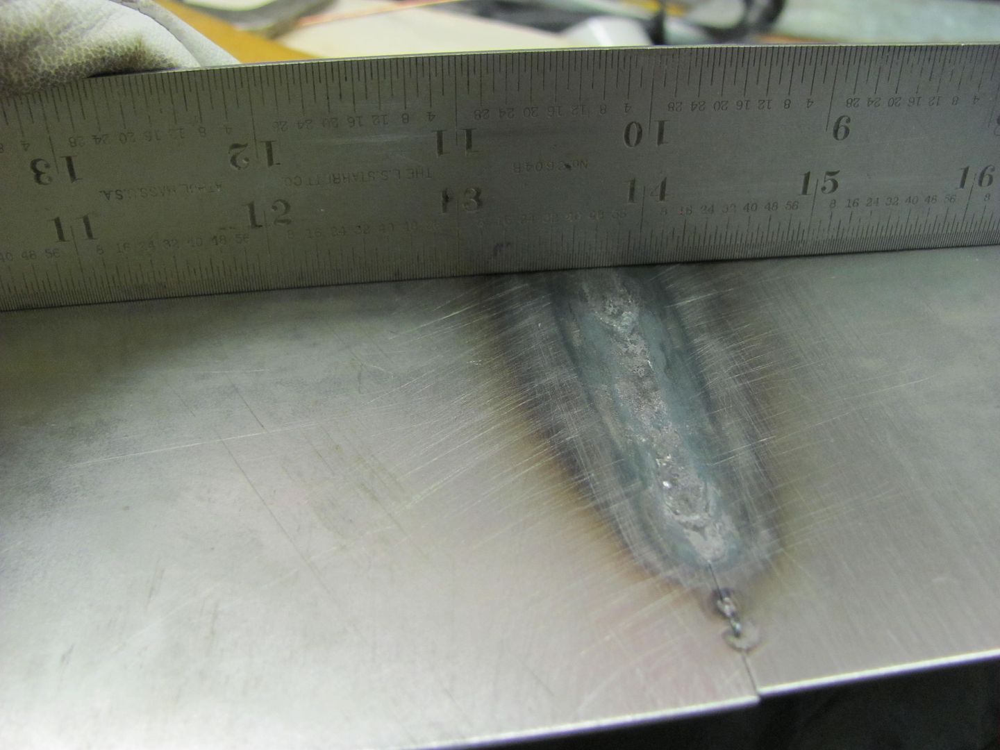
Fusion welding:
The little bit of undercutting on the back side is from just a bit too much heat, which is controlled by increasing the speed at which the torch is moving.
Too bad you don't live a bit closer (and I was done with this wagon) we could get that knocked out in a weekend.
If you are up on your skills in fusion welding, this would help to eliminate much of the distortion, but the joints will need to be ABSOLUTELY TIGHT. If you plan on using MIG, find some EZ grind or the ER70S-7 that I've been using. I think the hardness of the weld bead of the standard -6 that comes with the MIG machines is going to make the process more difficult in the long run that it would be well worth the new wire...
Fusion welding:
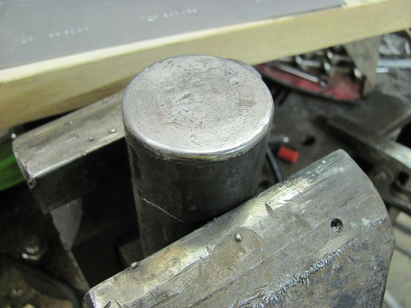
OK, you guys have been hearing me talk about fusion welding and since I was in the shop today I decided to show a sample of the TIG fusion welding. This takes me a bit out of my comfort zone, as I normally pick up the MIG, but here we go. Separate halves tacked together:
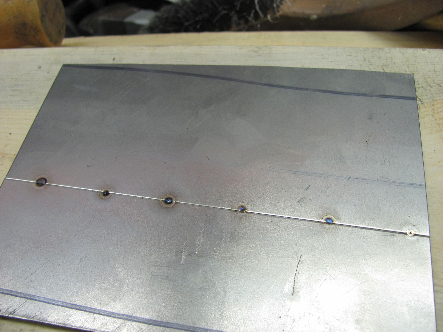
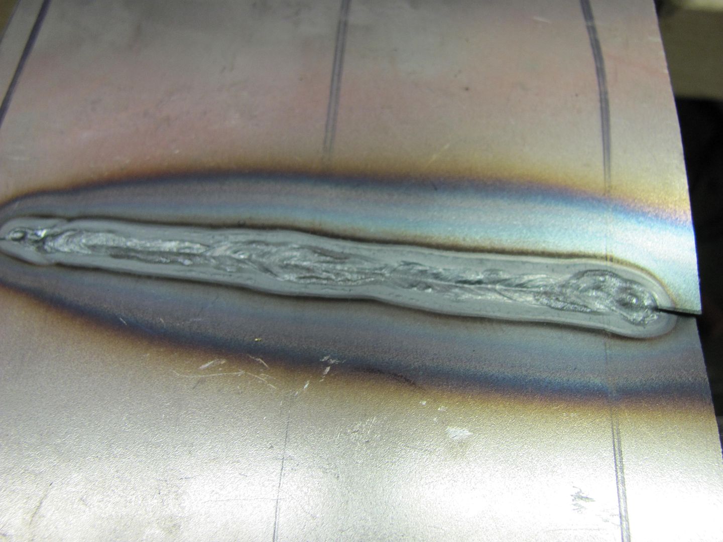
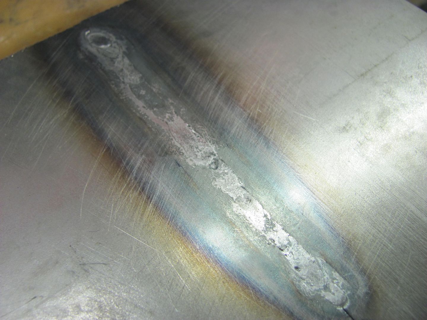
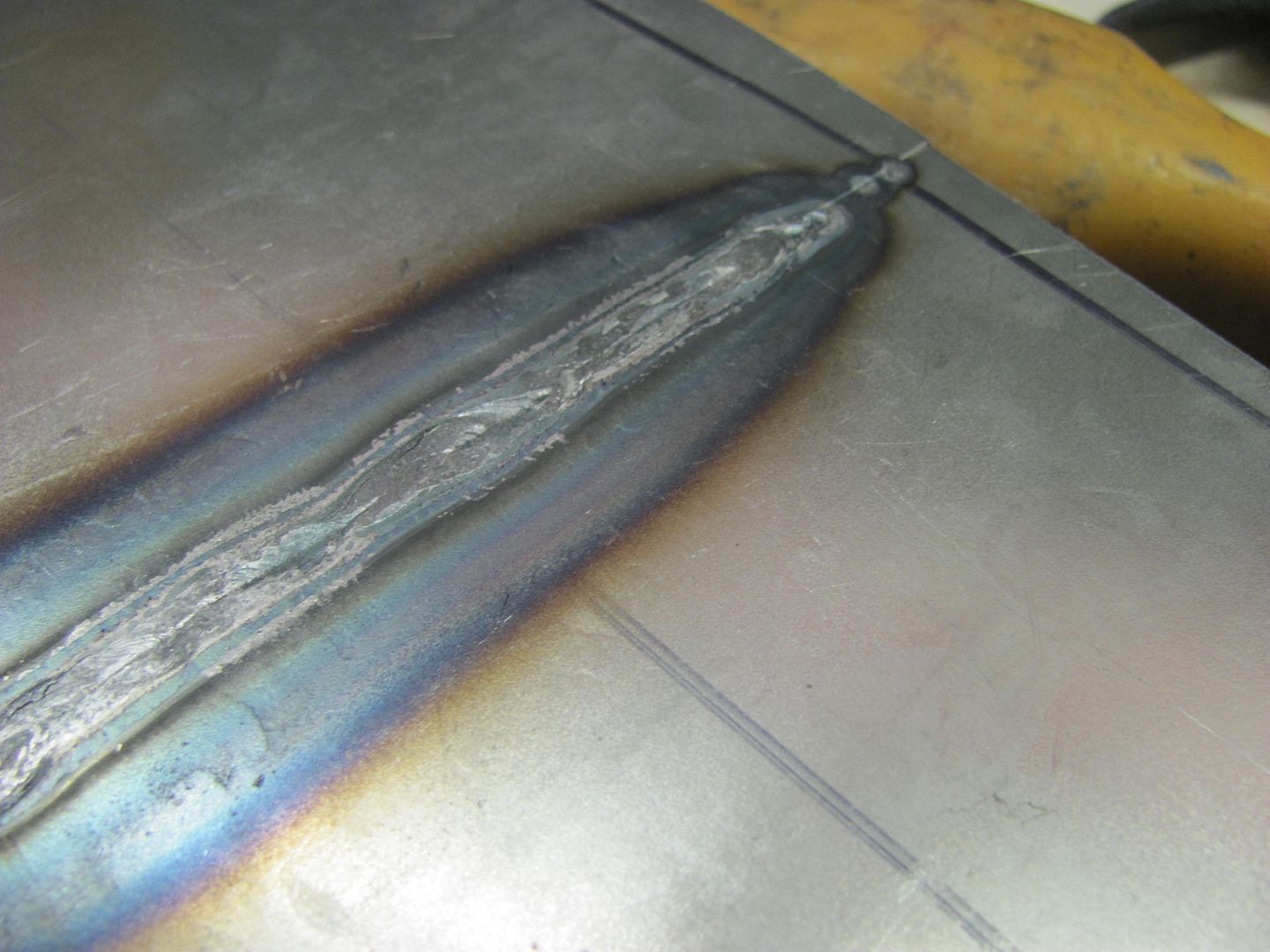
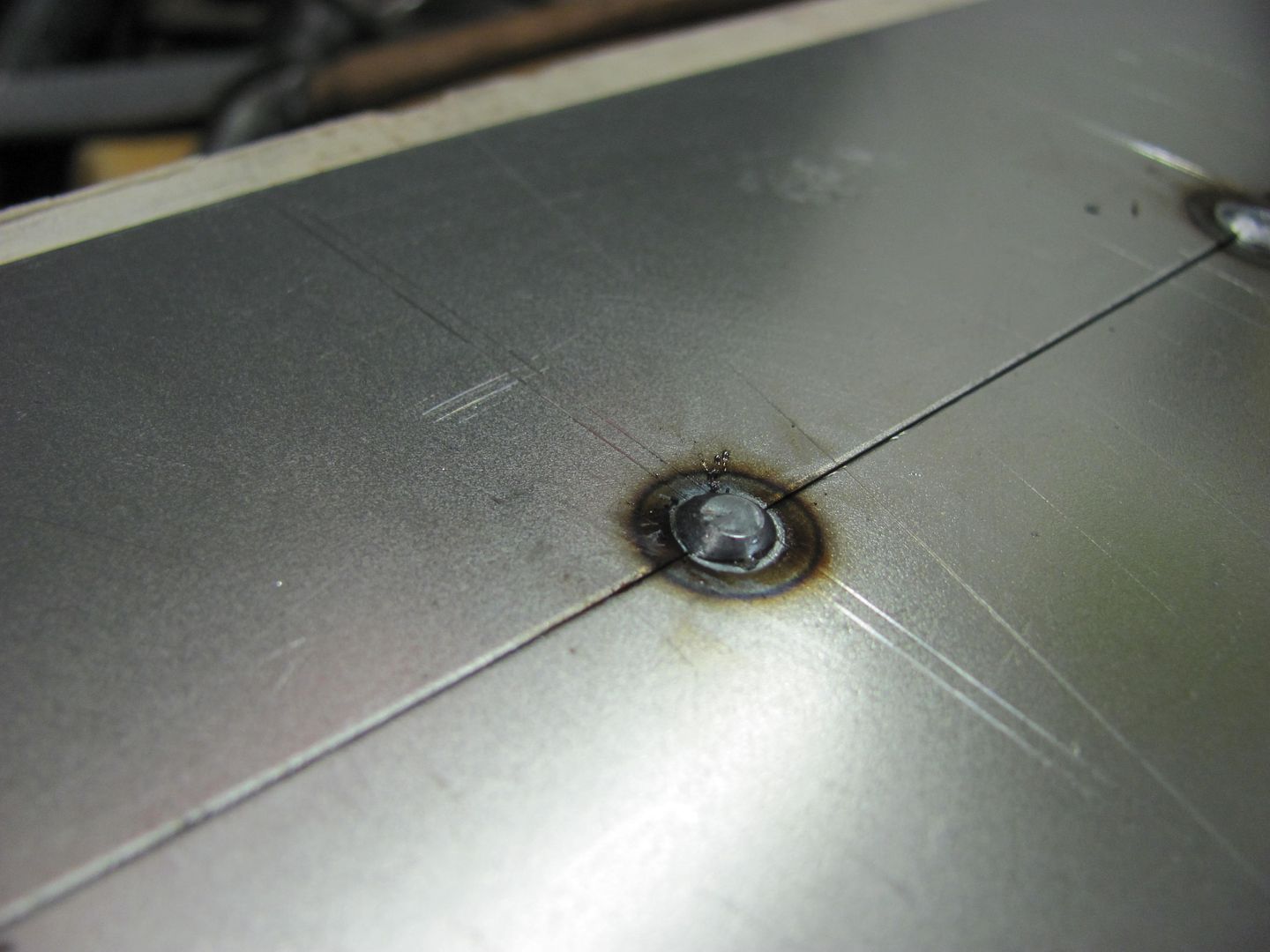
Note the lack of/minimal amount of HAZ around the tacks. This was accomplished by holding the electrode as close as you can without touching and using a quick zap. If held farther away from the panel, you see more blue HAZ surrounding the tack. Here is the fusion weld, no filler added.
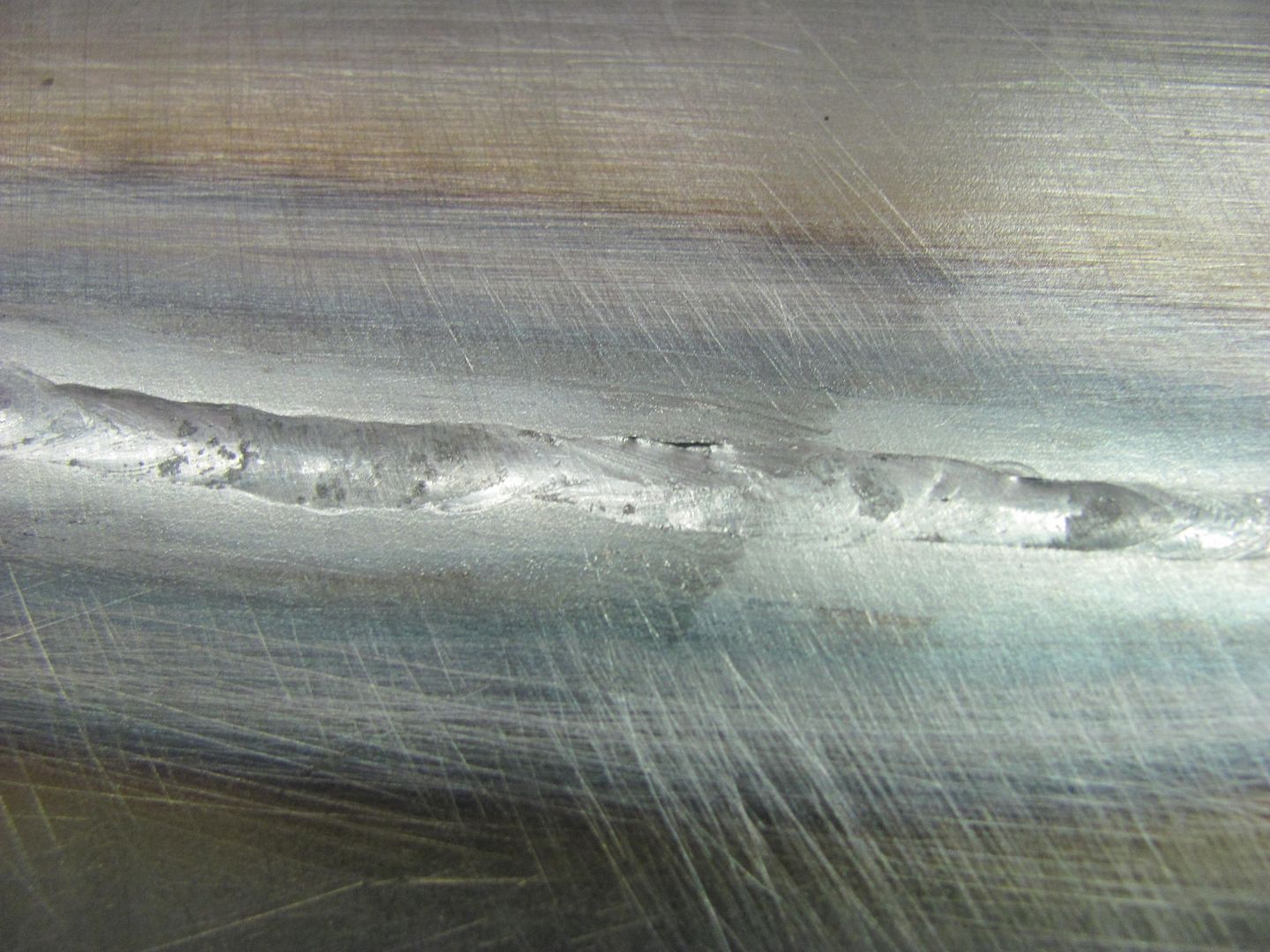

Back side.....
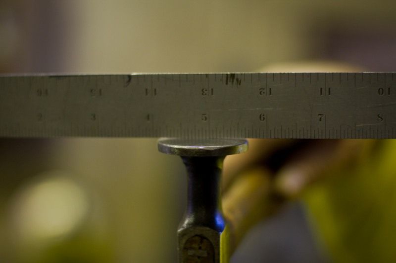
Then, using this anvil to planish out the weld and HAZ:
Results in this:
Front
Back
Nice and flat, no grinding required (in this case)
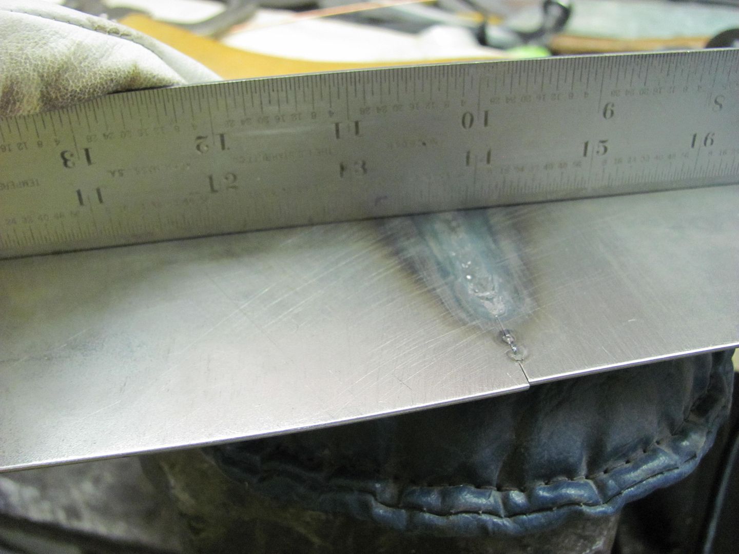
This method requires having an absolute tight joint, so fitment will be more time consuming, but just imagine all the time just saved over dressing out a MIG weld...
The little bit of undercutting on the back side is from just a bit too much heat, which is controlled by increasing the speed at which the torch is moving.
Too bad you don't live a bit closer (and I was done with this wagon) we could get that knocked out in a weekend.
Last edited:
1971gsfan
Well-known member
Robert
I thought the pics were too small, I can enlarge them later. I have my original hood and spare that is damaged to cut up for this project. I hope to have this done when its time for paint so I can paint the stock hood and the one I'm modifying. When I get going I'll post some pics of the progress. Fusion welding is pretty cool. I did some while in college through a welding class.
Again I thank you guys for your time responding to my questions
1971gsfan
Well-known member


OK, I'm sure I'm missing some details, like a cold induction air cleaner that may have to be modified, so these thoughts subject to change pending verification of hood/car..... (disclaimer)
But I would think that cuts made as shown. Side cuts about 1/2 to 2/3 up the ramp where hood raises, depending on match to new added sides. Vents trimmed off back to eliminate both upsweep and vents. Depending on air cleaner configuration, either slide section back and re-hem back edge after trimming vents for new back edge, or leave in place and add new rear section. I don't know how the front will react to being raised up, hence the two options there. The front may roll up just fine, then again adding a new section in front and sliding center backwards may provide better transition at the front.. But once sheet metal is cut, repositioned and tacked in place, then you will very likely need to separate outer skin and inner frame to planish welds and modify inner frame as well.. Given the amount of work to hammer form those hood scoop openings in a plain hood, it may be wise to find a GSX hood in similar "needing repair" condition to graft into the center section..

But I would think that cuts made as shown. Side cuts about 1/2 to 2/3 up the ramp where hood raises, depending on match to new added sides. Vents trimmed off back to eliminate both upsweep and vents. Depending on air cleaner configuration, either slide section back and re-hem back edge after trimming vents for new back edge, or leave in place and add new rear section. I don't know how the front will react to being raised up, hence the two options there. The front may roll up just fine, then again adding a new section in front and sliding center backwards may provide better transition at the front.. But once sheet metal is cut, repositioned and tacked in place, then you will very likely need to separate outer skin and inner frame to planish welds and modify inner frame as well.. Given the amount of work to hammer form those hood scoop openings in a plain hood, it may be wise to find a GSX hood in similar "needing repair" condition to graft into the center section..
Last edited:
1971gsfan
Well-known member
Robert
That is kinda what I'm thinking. I would cut like you outlined in red and the lines a added in white would be the "raised" portion. I will practice to see if I could bend the sides and front down from about where the white lines are or if it would be easier to bend the sides from a separate piece of metal and tack on where the white lines are. I want it to be 2 to 3 inches higher I could buy a metal cowl scoop and take the sides and possibly the front off it and tack to my center section as well. I guess there are several ways to do it. For the back or rear I could bend something similar to the bolt on cowl scoop rear as mentioned above. After looking at the post it might be easier to graft just the center scoops onto a cowl hood scoop like in the picture and weld that onto another skylark flat hood creating a gs cowl hood.
Also I hope I'm not highjacking your thread asking all these questions. I was interested in your advice and opinions
Again thanks
Tim
Attachments

Kevin54
MEMBER EMERITUS
Robert
That is kinda what I'm thinking. I would cut like you outlined in red and the lines a added in white would be the "raised" portion. I will practice to see if I could bend the sides and front down from about where the white lines are or if it would be easier to bend the sides from a separate piece of metal and tack on where the white lines are. I want it to be 2 to 3 inches higher I could buy a metal cowl scoop and take the sides and possibly the front off it and tack to my center section as well. I guess there are several ways to do it. For the back or rear I could bend something similar to the bolt on cowl scoop rear as mentioned above. After looking at the post it might be easier to graft just the center scoops onto a cowl hood scoop like in the picture and weld that onto another skylark flat hood creating a gs cowl hood.
Also I hope I'm not highjacking your thread asking all these questions. I was interested in your advice and opinions
Again thanks
Tim
'71......with your fiberglass hood, the sides are rolled. If you add an aftermarket cowl scoop like you show, the sides are squared, and that scoop cowl scoop would be considerably narrower than what your hood area is now. If you don't mind the squared sides, then you may want to split the cowl scoop down the middle and add a new center section in to cover the area of your raised portion that is in the hood currently. If that makes sense. Then add the scoops into the widened out portion.
1971gsfan
Well-known member
Kevin54
The fiberglass gs cowl hood is what the finished product will look like, I don't have a fiberglass hood. The FG hood is pin on. I don't like that. I would definitely roll out the square sides for the more rounded factory look if I used an aftermarket scoop. Like you said it would be narrow so I would cut the sides off, roll them out some and then weld that to my center section. splitting it down the center like you said might be about the right width. Then I would weld that new scoop to a skylark hood which is flat.The idea is to have a metal cowl induction hood with my GS cold air intakes in it.I have never seen it done so I want to do it. It is a big hobby project for me after that I would have to rework the underside for a stock look.
Tim
The fiberglass gs cowl hood is what the finished product will look like, I don't have a fiberglass hood. The FG hood is pin on. I don't like that. I would definitely roll out the square sides for the more rounded factory look if I used an aftermarket scoop. Like you said it would be narrow so I would cut the sides off, roll them out some and then weld that to my center section. splitting it down the center like you said might be about the right width. Then I would weld that new scoop to a skylark hood which is flat.The idea is to have a metal cowl induction hood with my GS cold air intakes in it.I have never seen it done so I want to do it. It is a big hobby project for me
after that I would have to rework the underside for a stock look.Tim
Tim, this is your car, so in the end the choice is yours. But IMO the bolt on cowl you show has far too sharp of corners to match the car. While the car didn't come with a cowl hood, my preference in doing these type mods to a car is to make it subtle enough that someone has to look twice (or more) to catch the difference.. or at least close enough to the style that someone may think it were original. I'll agree that cowl induction hoods aren't that subtle, but I think you may have better results with a "ramped" side similar/steeper than that of the original.. Rather than buy the bolt on scoop, that IMO doesn't match any part of the hood, I would form some sheet metal that accomplishes the ramped sides, and weld the pieces together. The front could likely be left intact, cut the side slices and see if you can do a "reform" on the leading edge. Form the cowl rear "extension" using bead roller, etc, and a tipping wheel to form the back hem that wraps around your newly formed inner structure.
As far as hijacking, the first post of this thread states the goal of this thread is to primarily focus on providing metalworking/metal shaping tutorials. I think this discussion fits that bill..
As far as hijacking, the first post of this thread states the goal of this thread is to primarily focus on providing metalworking/metal shaping tutorials. I think this discussion fits that bill..
1971gsfan
Well-known member
Robert
Yeah I know what you mean the "style" of my hood. The square scoop definitely will not match. I want it to look like it could have been a stock option. In the picture I added the white lines that will be about where the bend will be I will probably only raise it about 2 inches
Tim
Yeah I know what you mean the "style" of my hood. The square scoop definitely will not match. I want it to look like it could have been a stock option. In the picture I added the white lines that will be about where the bend will be I will probably only raise it about 2 inches
Tim
Robert,
Having just read through the entire thread I have to say your work is fantastic and a massive inspiration to those of us who will never make anything of ourselves because we charge more than a bondo-weilding bodyshop.
I have a small query harking back to the start of the thread if you wouldn't mind explaining something for me.
For years I have tacked, slapped with a hammer then ground the weld down. What I would like to know is how do you planish the weld whilst it is still a full proud lump of metal?
Thanks in advance
Pete
Pete, sorry so long to respond, been on a cruise with no internet...
For planishing the welds like you see in the fender shaving pics, I use a low crown hammer on the outside and a dolly on the inside, dolly closely matched to the contour of the inside of the panel.. Unless the outside is concave, then go to the high crown body hammer..
If you've ever smacked the dolly with the hammer, this is very similar to the sound you're looking for. I have done some rather inaccessible planishing by using my nephew on the inside with the dolly, and me on the outside with the hammer. Some light taps will verify if you are aligned on the correct "dot" as you will hear that metal on metal sound. Then a couple of good raps, and grind them just above panel surface using a cutoff wheel. Here's one that has been planished:
The grinding process would be similar to what I show here in grinding plug welds, although on weld seams I wait on the roloc sander cleanup until the end. This helps to minimize any chance of repeated hitting the panel on either side of the weld and thinning the panel. Once all the weld seam has been done end to end and planished and ground to above panel surface, then any remaining panel defects from welding can be addressed with dolly and ******* or even the hammer still if it needs the extra oomph. On a plug weld, when it's done, it's done, sand away.
http://s5.photobucket.com/user/rmccartney/media/1955%20Chevy%20Wagon%20Restoration%20Album%203/Grindingplugwelds.mp4.html
I've recently gone from the ER70S-6 wire to ER70S-7 and have found the -7 to have better wetting properties (better flowout, less proud) and less tensile strength for easier grinding and planishing. I made no machine adjustments when I put in the -7, just changed the wire, and it was NOTICEABLY easier to planish and grind.. Just having less proud helped out tremendously. I've got some new -7 coming in the smaller .023 wire, so hopefully that helps s a bit more as well.
.
Last edited:
BigMike782
Well-known member
been on a cruise with no internet...
Hopefully not on Royal Caribbean.
What is the purpose of planishing prior grinding?
Last edited: