To avoid these ads, REGISTER NOW!

MP&C Shop Projects

Kevin54

MEMBER EMERITUS
Joined
Jan 12, 2005
Messages
29,341
Location
Urbana, Ohio
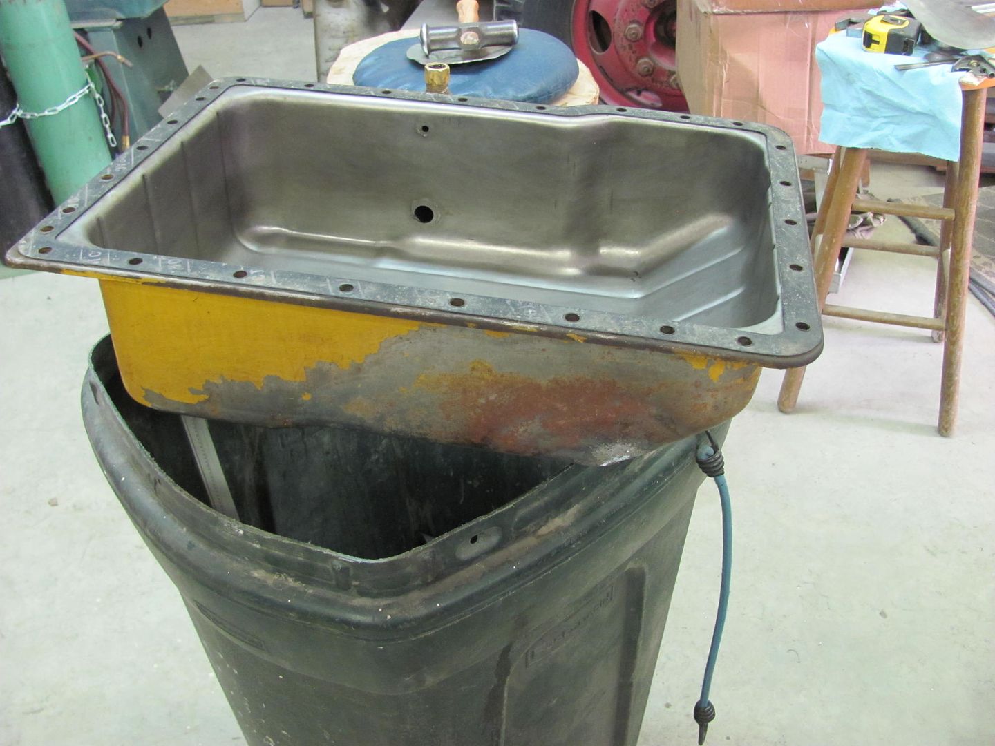
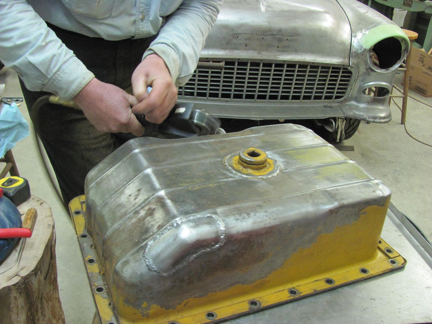
As a follow up to the valve cover repairs, the owner has the car just about ready, just needs some tune up work...


100_2939.jpg


100_2941.jpg


100_2945.jpg


100_2946.jpg

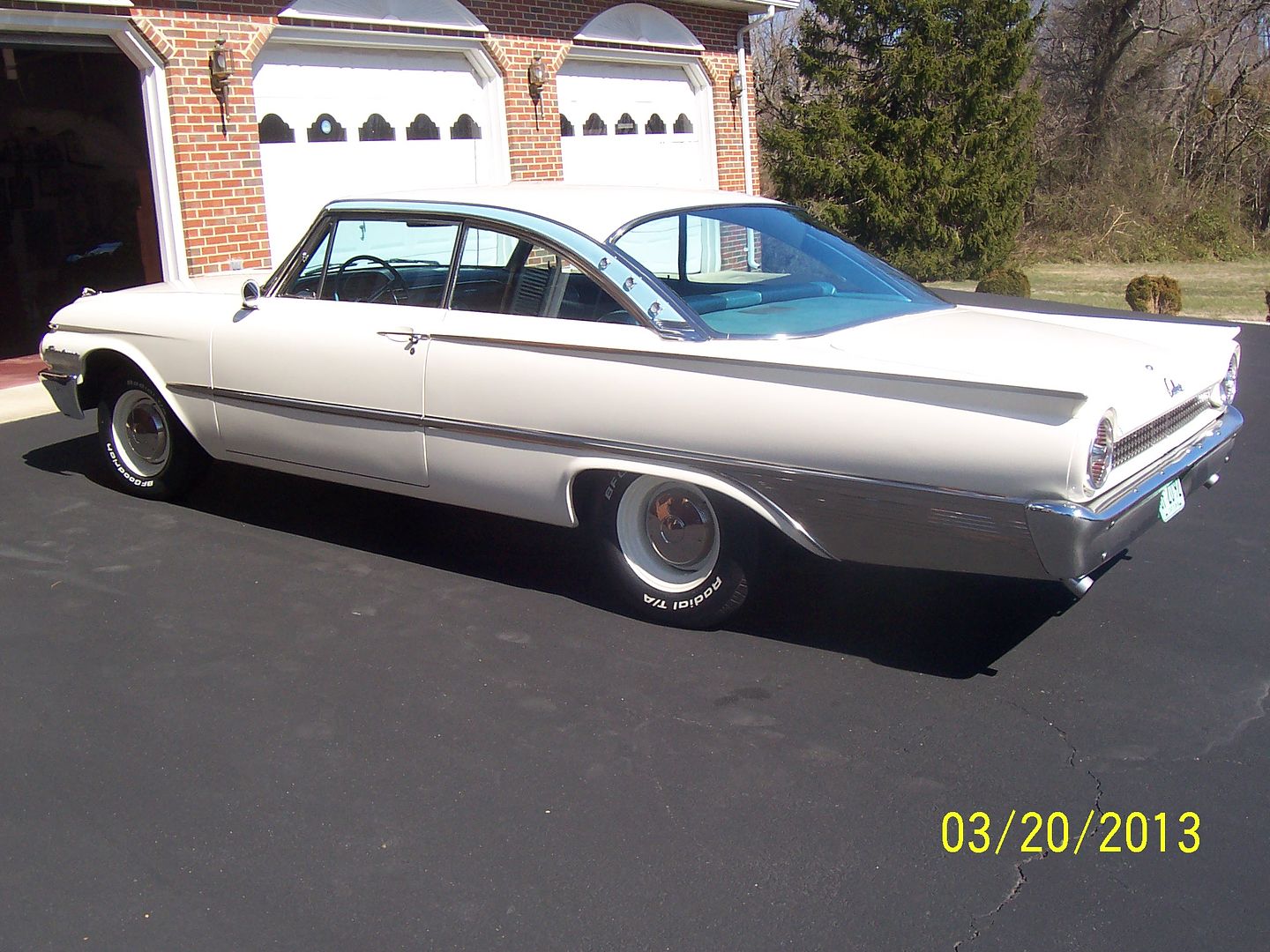
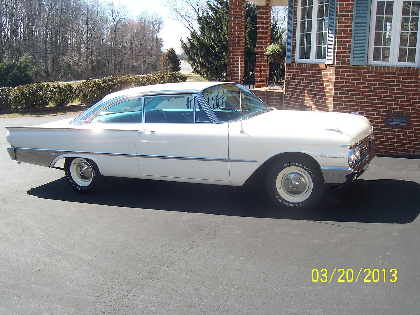
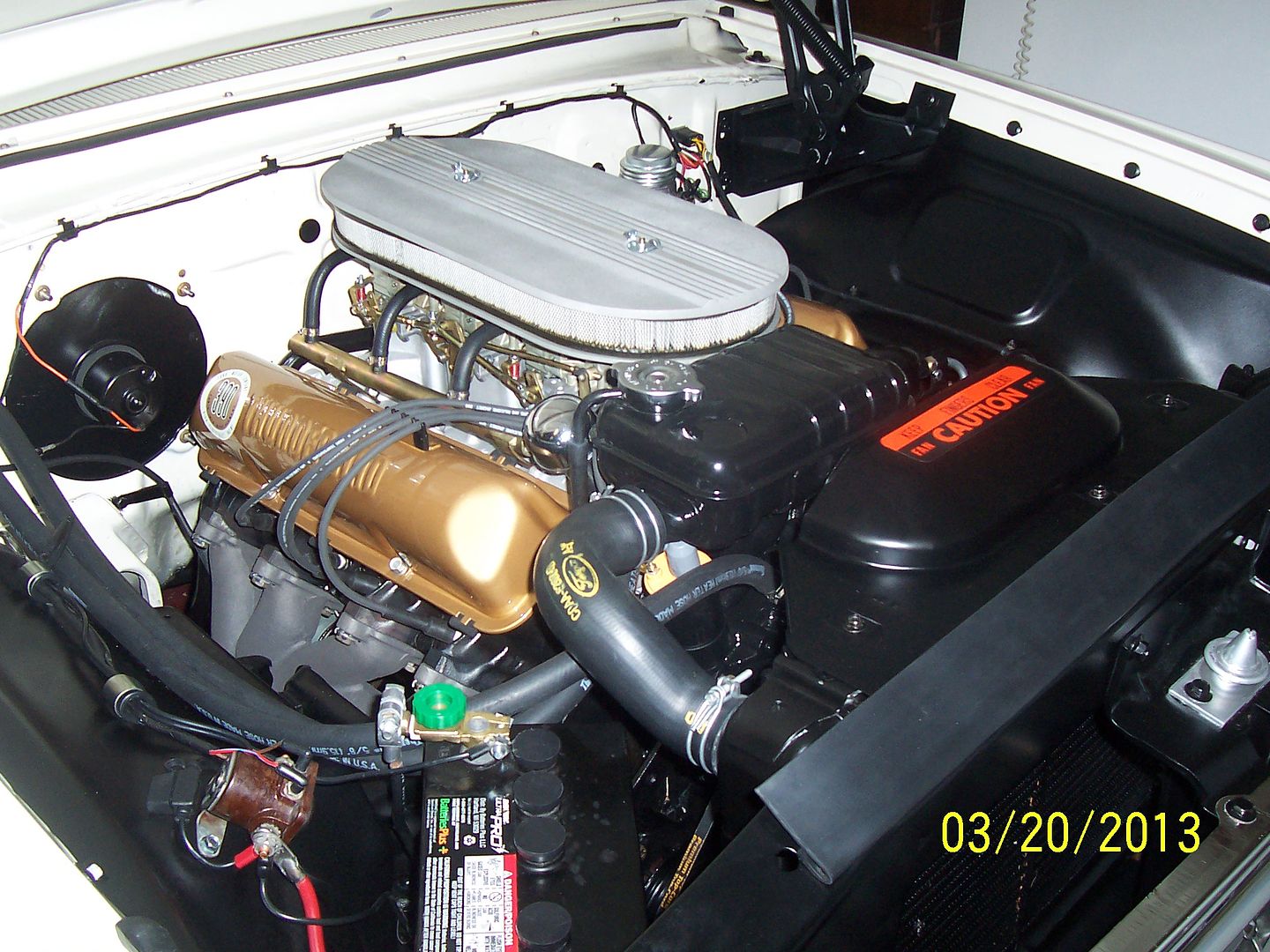
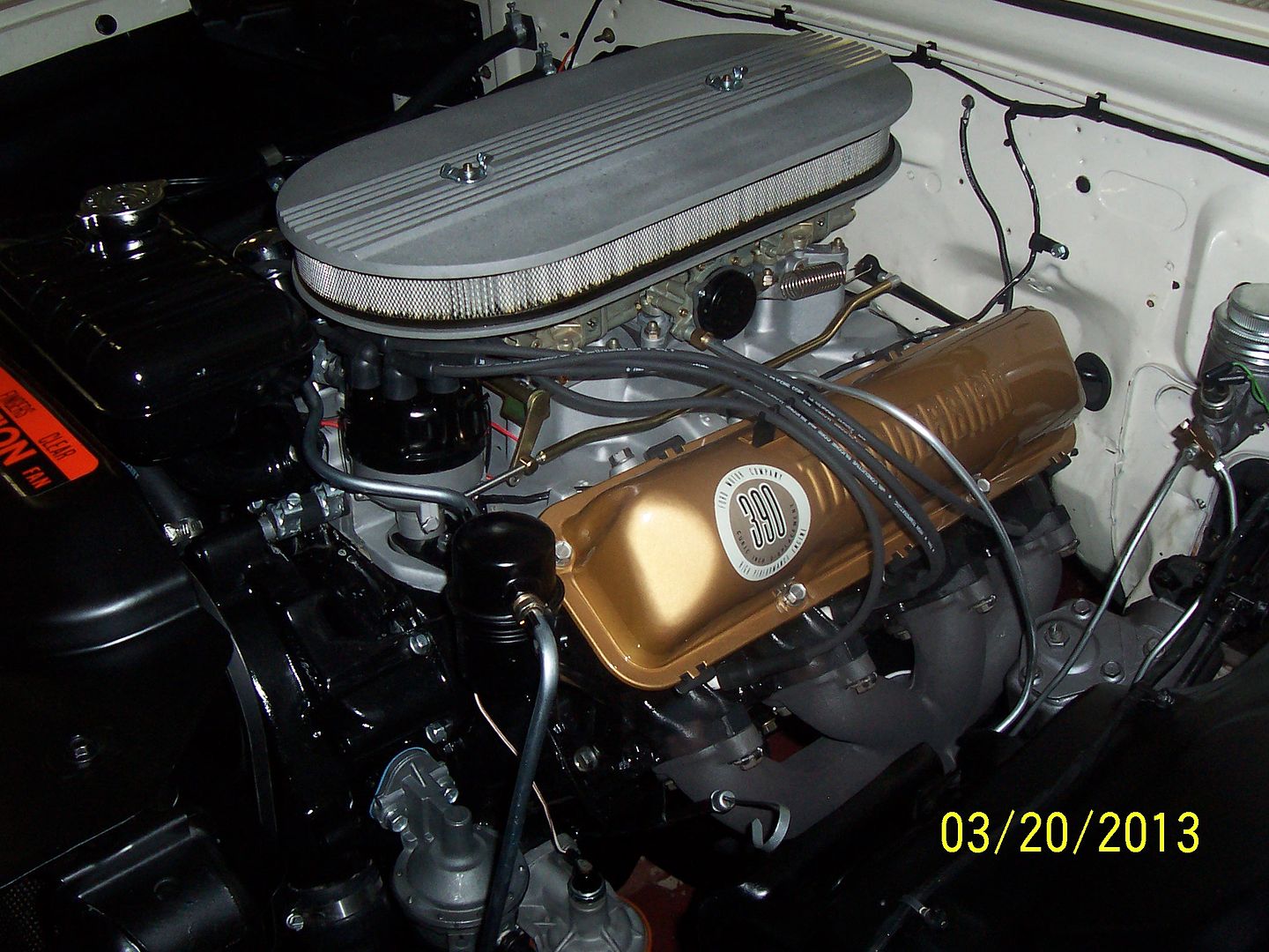
Sweet!!!! 4 speed or Auto? I'ma likin' a 390 with dual fours though :thumbup:
 
To avoid these ads, REGISTER NOW!
OP
M

MP&C

Well-known member
Joined
Oct 21, 2009
Messages
4,396
Location
Leonardtown, MD
Kevin, it's a 390 4 speed. It came with 2-4's when he bought it, but he took those off in favor of the three dueces the car would have come with from the factory.
 
Last edited:
OP
M

MP&C

Well-known member
Joined
Oct 21, 2009
Messages
4,396
Location
Leonardtown, MD
Boy, an apprentice sure is tempting....

Well, with this next post, I guess we'll find out who missed out on an auction with two seconds to go... :willy_nil

I had been looking for a blocking hammer and one appeared on ebay the other day, I won the auction and it showed up today. Here's one of the auction pictures, all of them were shown like this from the side...

Picture201-2.jpg


This was described as:

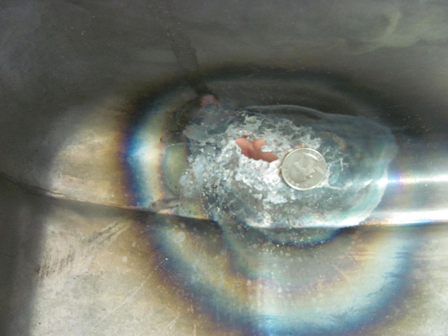
It's in great condition as you can see in the pics ,the only thing is it has some light engraving by the logo


I guess my perception of great condition is a bit different, as this is what the faces look like....


Picture202-2.jpg


Picture203-2.jpg


Picture204-2.jpg


Nonetheless, I had planned on cleaning up the faces, just not quite that much... :lol_hitti


Picture206-2.jpg


Picture208-2.jpg


Picture209-2.jpg


This was done with a 60 grit roloc and then changed to a 120....


Picture210-2.jpg


....then changed to a scotchbrite pad....


Picture211-2.jpg


Picture212-2.jpg


Picture215-2.jpg


then used the DA and trizact pad


Picture213-2.jpg


Picture214-2.jpg


Picture217-2.jpg


Added a spare handle I had in the shop and tried it out....


Picture218-2.jpg


Picture219-2.jpg


Picture220-2.jpg


Then touched up a bit on the wheel..


Picture224-2.jpg


Here's the comparison between this hammer and one of the body hammers...


Picture221-2.jpg


Picture222-2.jpg


Should come in handy..
 
OP
M

MP&C

Well-known member
Joined
Oct 21, 2009
Messages
4,396
Location
Leonardtown, MD
It would be used for shaping metal, like here:


_MG_9965.jpg


The wooden bat hammer and the plastic type mallets just don't have enough "heft" to provide the stretch needed for adding shape to 18 ga steel. They are more suited to use on aluminum. This Pexto blocking hammer is more effective at adding shape to a steel panel.
 
Last edited:
OP
M

MP&C

Well-known member
Joined
Oct 21, 2009
Messages
4,396
Location
Leonardtown, MD
So just when do you decide to use that 'nuclear solution'? It looks hefty enough to be used for straightening a bent frame! lol


Here's a sample....18 ga steel, flat as shown. Used the Pexto blocking hammer and a shot bag filled with No. 8 lead shot.


Picture225-2.jpg


Picture226-2.jpg


After less than a minute, here's the amount of shape added to the panel.


Picture227-2.jpg


Picture228-2.jpg
 
OP
M

MP&C

Well-known member
Joined
Oct 21, 2009
Messages
4,396
Location
Leonardtown, MD
Started back in the wagon tonight, the rear hatch was a bit snug for the opening the factory provided.


Picture182-1.jpg


Picture186-1.jpg


Rather than risk certain chipped paint, we'll work to get the gaps more consistent...


Picture190-1.jpg


Picture191-1.jpg


Then the edge was ground to our mark and some c-clamp vise grips held all three pieces snug while they were tacked in place.


Picture193-1.jpg


Picture194.jpg


Picture196.jpg


Then the top and bottom sides of the weld are ground flush with the panels. This removes the bulk of the weld and makes it easier in trimming the side....


Picture197.jpg


Picture198.jpg


Marked again....


Picture199.jpg


....and ground to yield a much better gap. One down......


Picture200.jpg


Yesterday/early this morning a question arose as to the correct thickness of the sheet metal on car hoods, specifically from the 50's to 70's time period. Well, since I'm all about using pictures to validate, here is a 1952 Ford hood and a 1955 Chevy hood that I just happened to have lying around....


Picture176-1.jpg


Picture178-1.jpg


Just to clarify any confusion and dispel any rumors of the Big 3 automakers using 16 or even 14 gauge sheet metal on the hoods, I thought this an opportune time to take some measurements. Just to be more precise, we'll use a micrometer.


Picture177-1.jpg


Picture181-1.jpg


Picture179-1.jpg


Picture180-1.jpg


Now looking at this ASTM chart, it would appear that both these readings fall within the tolerances for 19 ga cold rolled steel. Humph. I'd have never guessed that.... :rolleyes:


:lol_hitti


ASTM-thicknessTolerance.jpg
 
Last edited:
OP
M

MP&C

Well-known member
Joined
Oct 21, 2009
Messages
4,396
Location
Leonardtown, MD
I guess that other thread gave you a lesson as well as a sore end. Lol!


No sweat, actually the dimension worked out to be exactly what I said it was. The rest of the guys gave the OP enough grief that I didn't want to pile on in that thread, but thought I'd post it to clarify any question.
 

Kevin54

MEMBER EMERITUS
Joined
Jan 12, 2005
Messages
29,341
Location
Urbana, Ohio
ASTM-thicknessTolerance.jpg


Of all the years I've worked around sheetmetal, I never knew that galvanized was that much thicker than hot or cold rolled.

You learn something new on here everyday!!!
 

e-tek

Well-known member
Joined
Dec 19, 2007
Messages
10,690
Location
Saskatoon, SK
Loved the gap work - not as easy as you make it look!! If you weren't so far away I'd be at the next class you're holding for sure!
 
Last edited:

Kevin54

MEMBER EMERITUS
Joined
Jan 12, 2005
Messages
29,341
Location
Urbana, Ohio
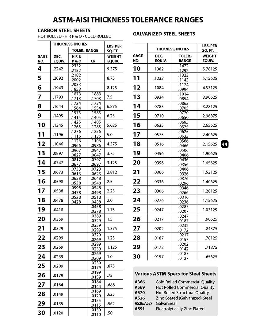
Kevin, my guess is that the difference is the thickness of the galvanized coating.

That's what I figured, but I never figured that galvanized coating would be that thick. The galvanize is adding around .002+/side. Not much to a carpenter, but quite a bit to a toolmaker :lol:
 
OP
M

MP&C

Well-known member
Joined
Oct 21, 2009
Messages
4,396
Location
Leonardtown, MD
Continuing on to the driver's side, this one is a bit tighter at the bottom than the other, shows about 1/32 gap. Used the compass again to mark the cut line...


Picture202.jpg


Picture204.jpg


Tacked, welded, and welds dressed...


Picture207.jpg


Picture208.jpg


All finished for this evening, have a couple pin holes to fix, will get them when we do the top...


Picture209.jpg


Picture210.jpg


New gap is right at 5/32", or to be more technical, one paint stick width....


Picture213.jpg


Picture211.jpg
 
OP
M

MP&C

Well-known member
Joined
Oct 21, 2009
Messages
4,396
Location
Leonardtown, MD
Thanks Sid!

Ok, one side left to go...


Picture214.jpg


Picture215.jpg


Picture216.jpg


Trimming to fit..........


Picture217.jpg


Welding the layers together....


Picture219.jpg


Picture220.jpg


Picture221.jpg


After dressing the welds..... I do have a couple pin holes to fix, but the gap is looking much better.


Picture224.jpg


Picture226.jpg


Picture227.jpg
 
To avoid these ads, REGISTER NOW!
OP
M

MP&C

Well-known member
Joined
Oct 21, 2009
Messages
4,396
Location
Leonardtown, MD
One of the other jobs on this car was to remove the hood ornament, and peak the hood. I recently had someone ask my preferred method for peaking a hood. He had wanted to cut out a strip and weld in. My concern with that method is that any shrinking from the welding and not enough planishing would be sure to result in a nice oil can. To show how well my method worked, I did a video to show how tight the hood was, no oil canning, and to show the detail a bit better. But first, a repeat of the forming process...

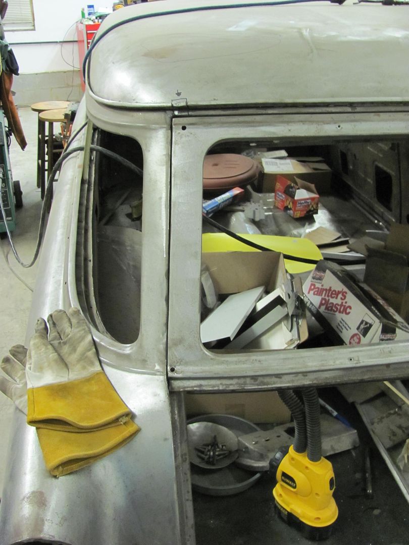
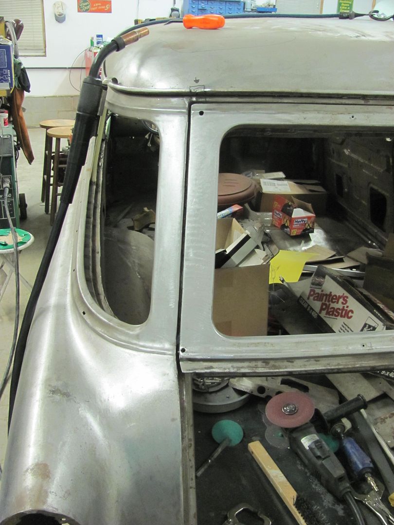
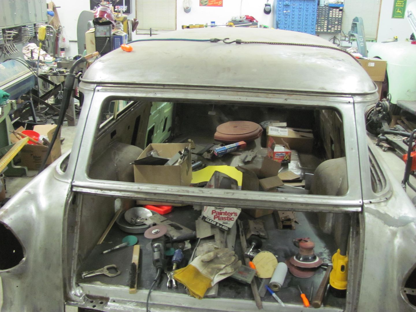
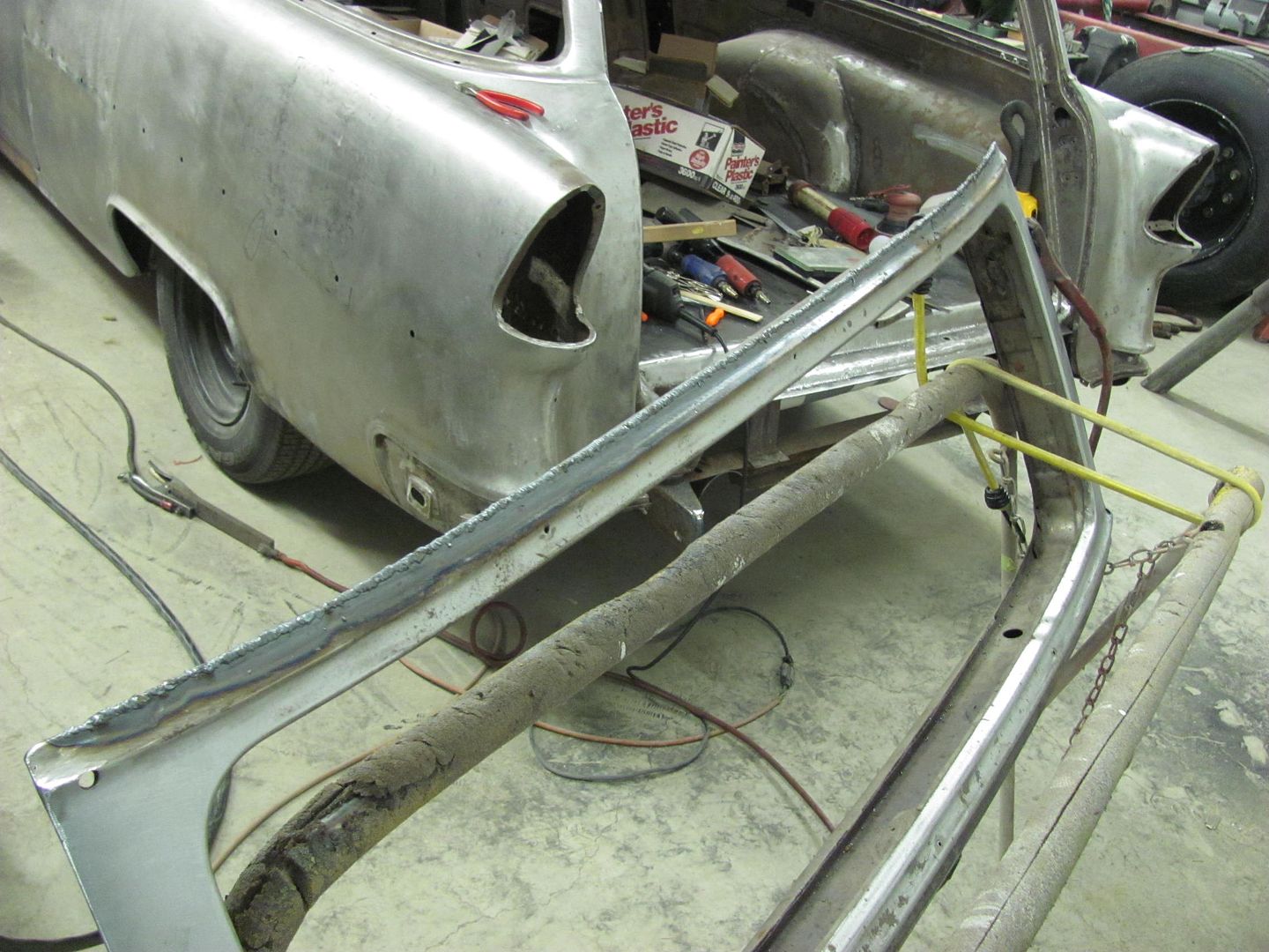
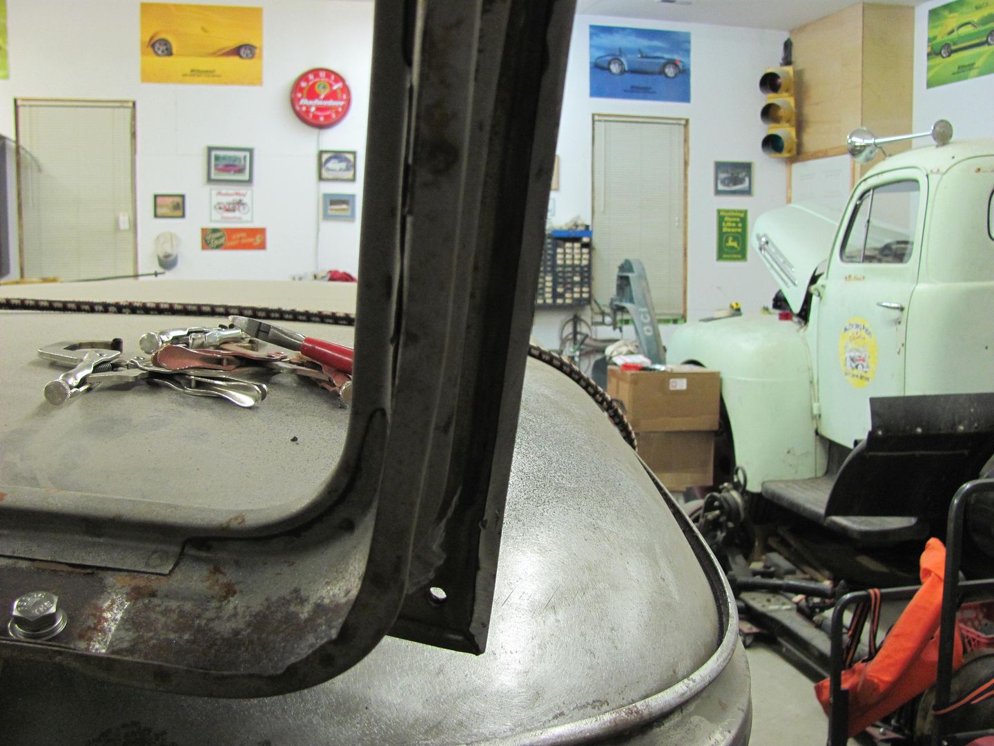
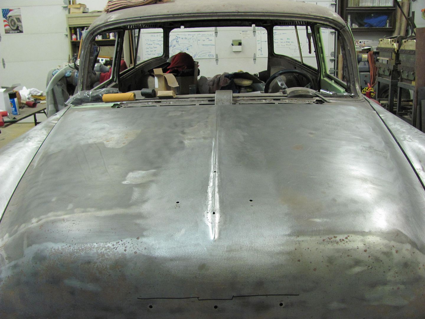
One of the tasks on the 55 is to de-bird the hood and bring the peak forward.

Picture482.jpg


Picture480.jpg


Picture481.jpg


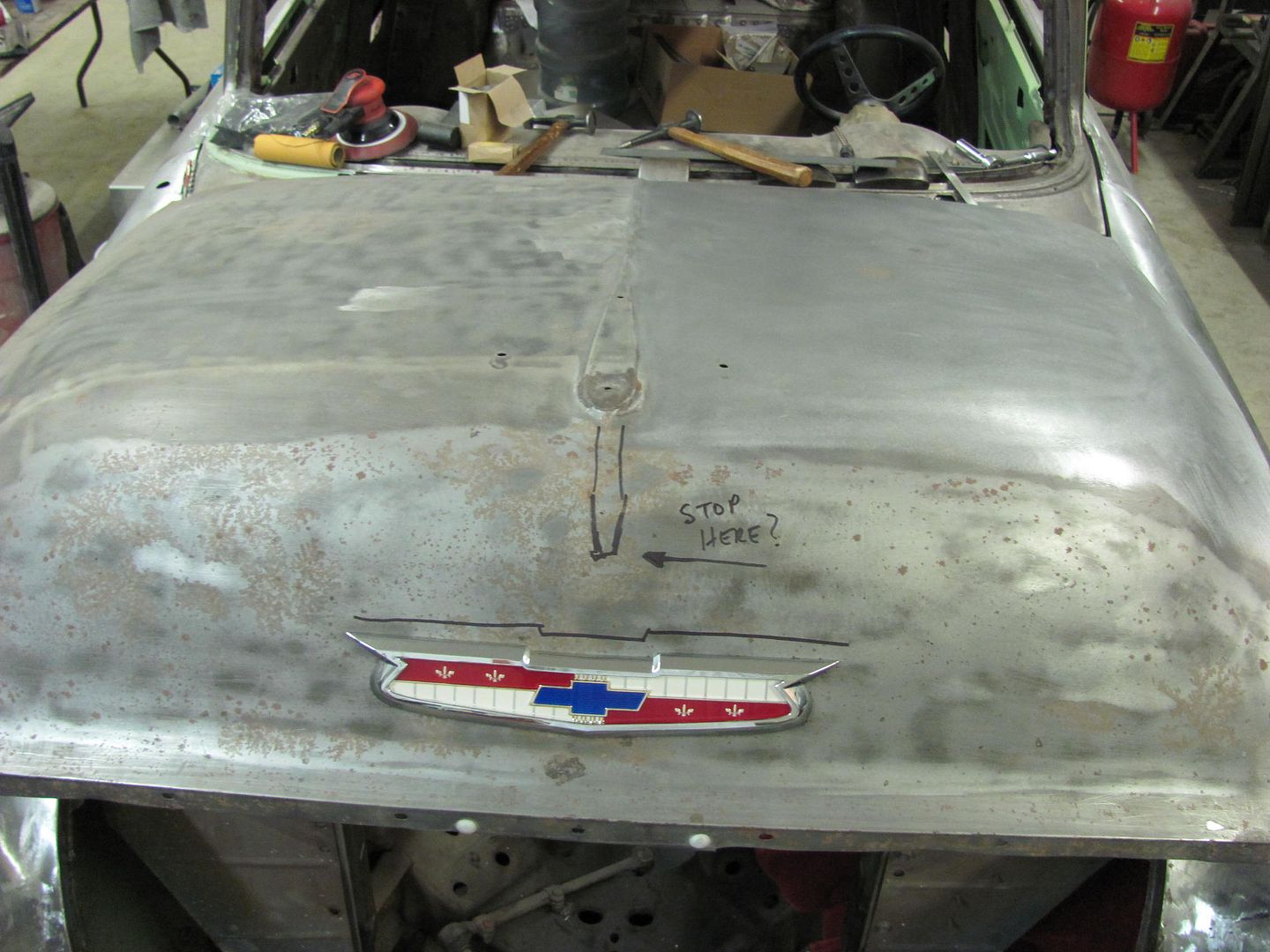
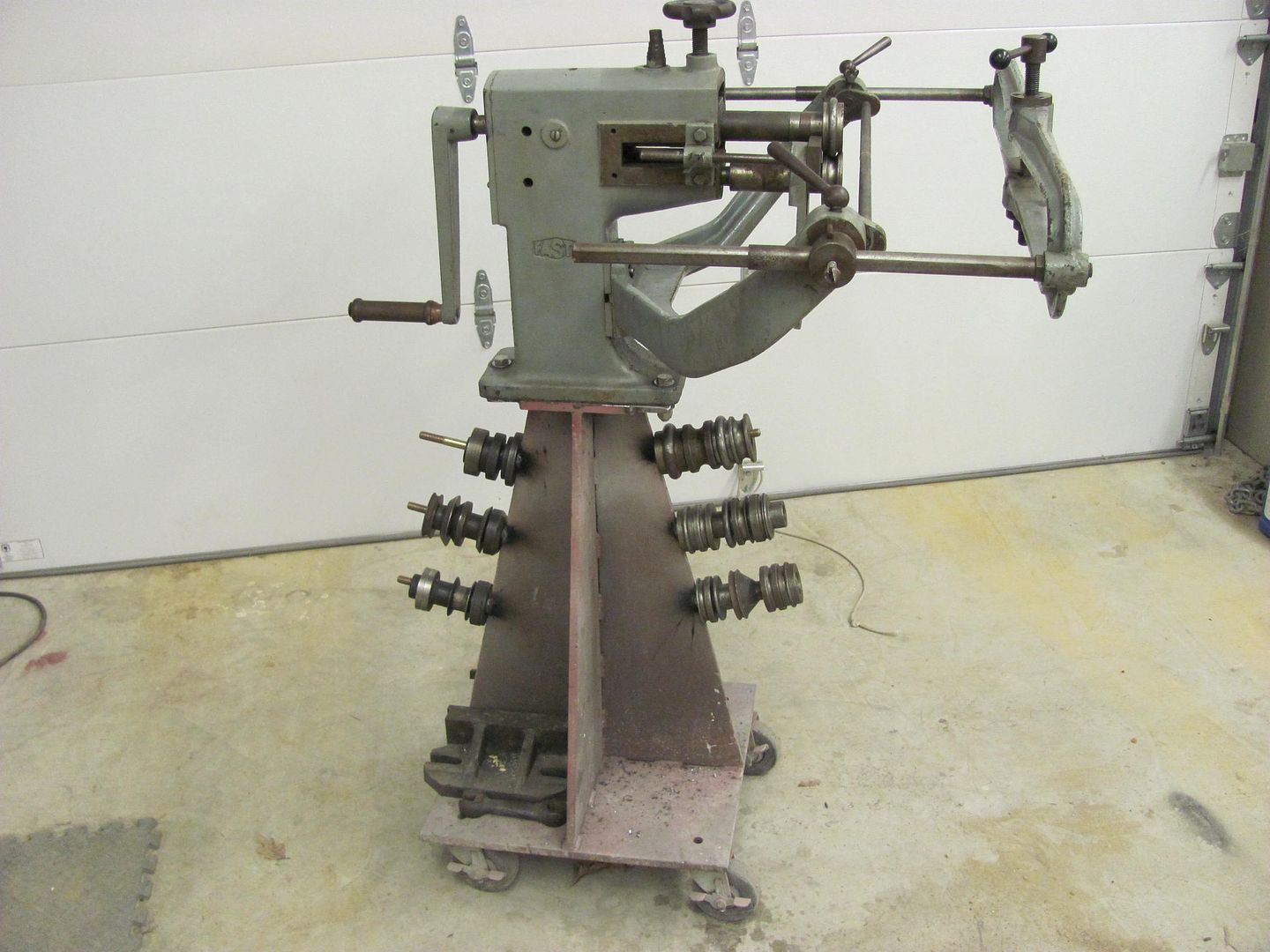
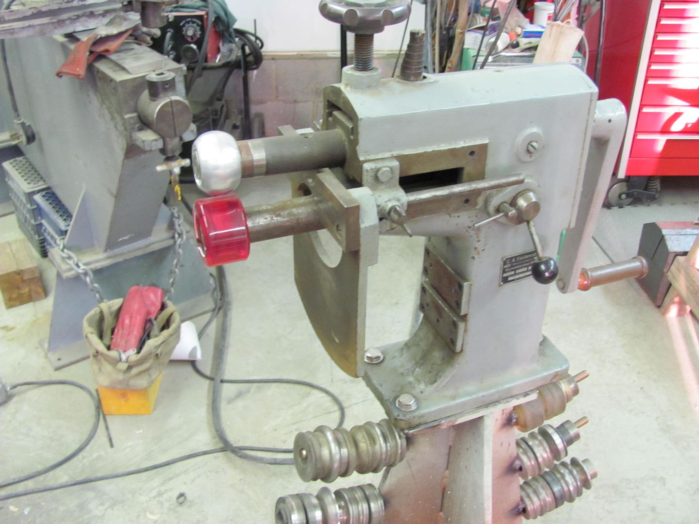
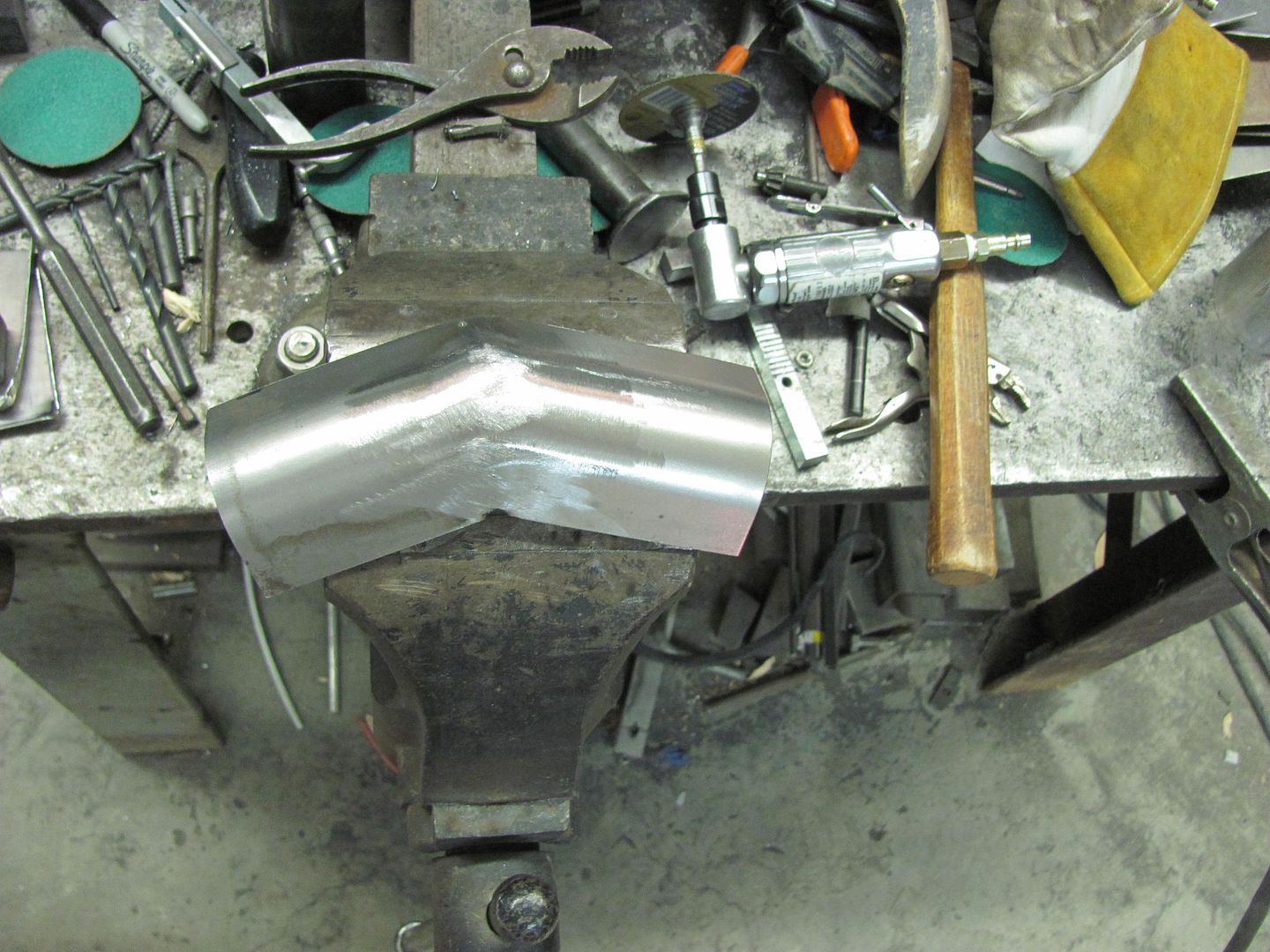
I know I can cut a strip out of the middle and duplicate a replacement with this little jewel...

Picture056.jpg


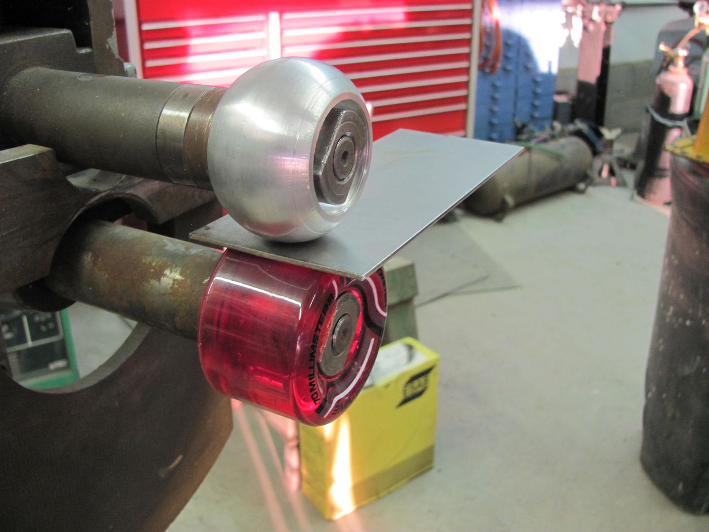
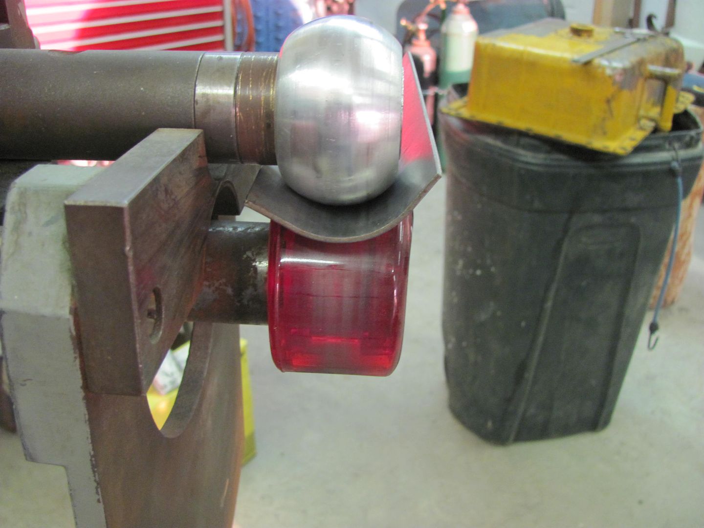
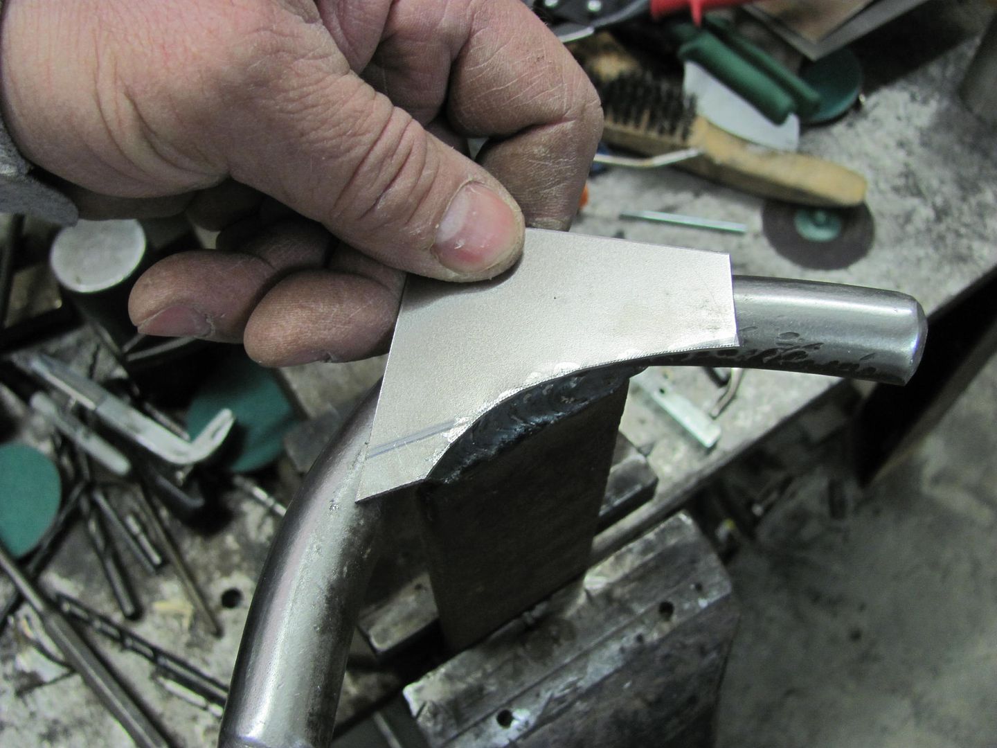
.....but this hood is relatively straight and rust free, so I'd like to keep it intact (without all that welding) if at all possible. I tried my hand at some manual "punch and die" tooling to see how well it might work, and all in all, it wasn't too bad although it will take some clean up afterwards:

Picture484.jpg


Picture485.jpg


Picture487.jpg


Picture488.jpg


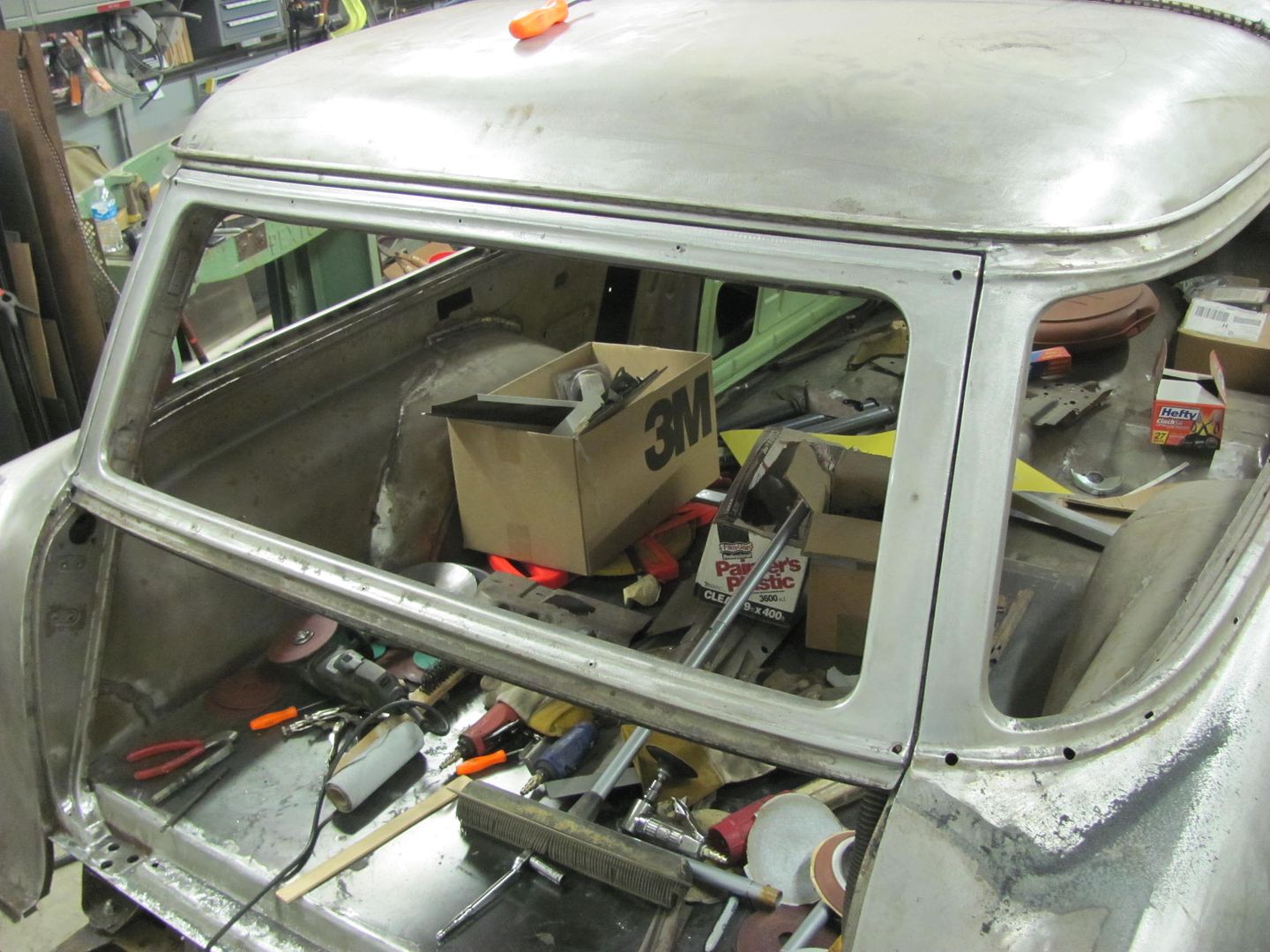
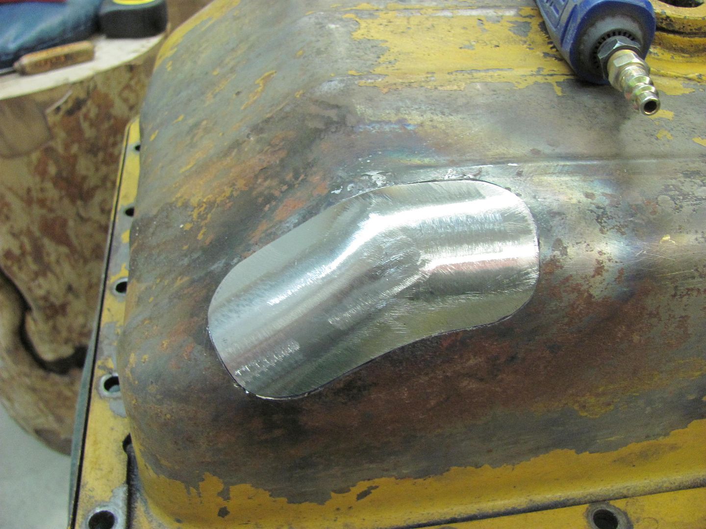
Results from the "start line"

Picture489.jpg


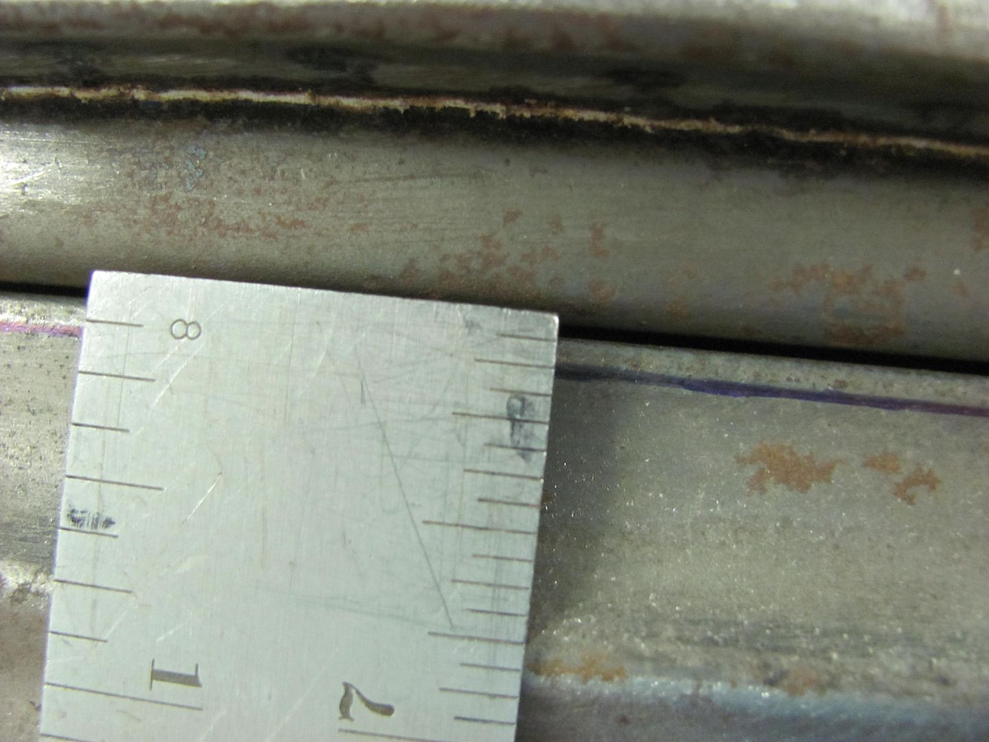
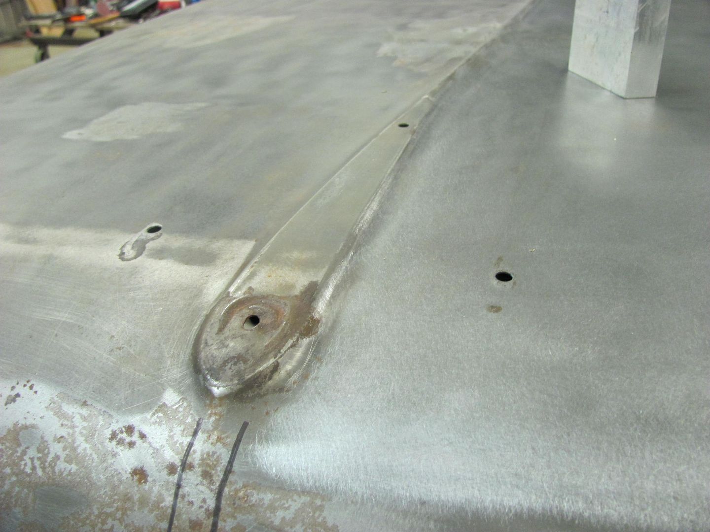
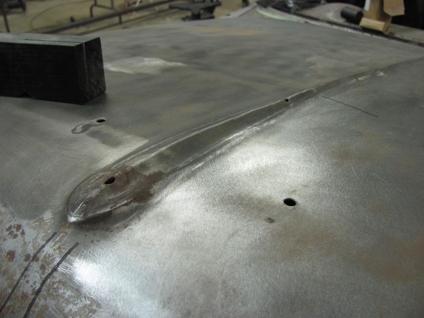
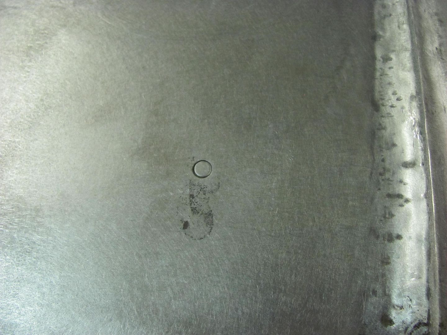
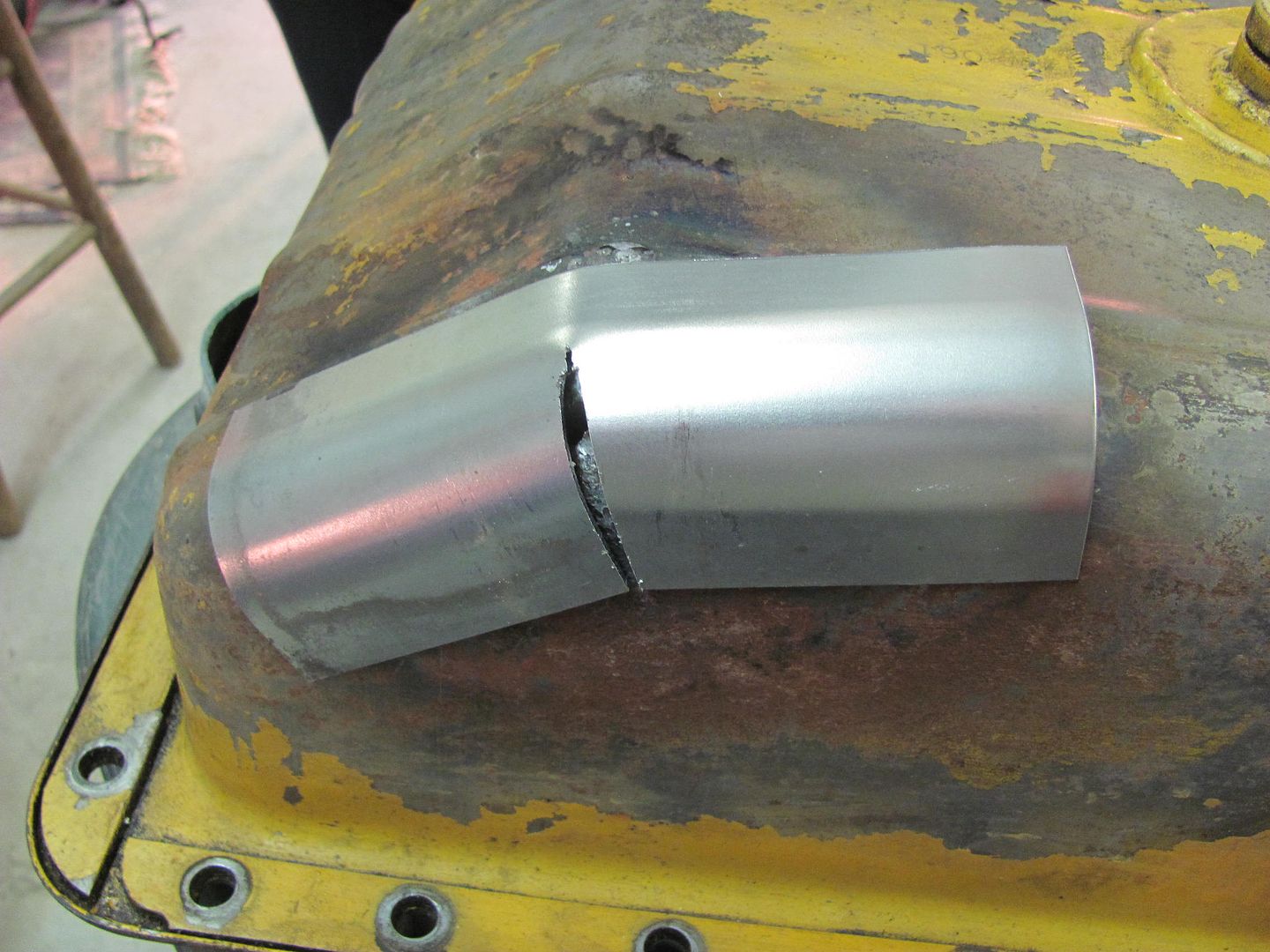
The pad, or "plateau" where the bird rested seems to have a nice crease around the perimeter.

Picture493.jpg


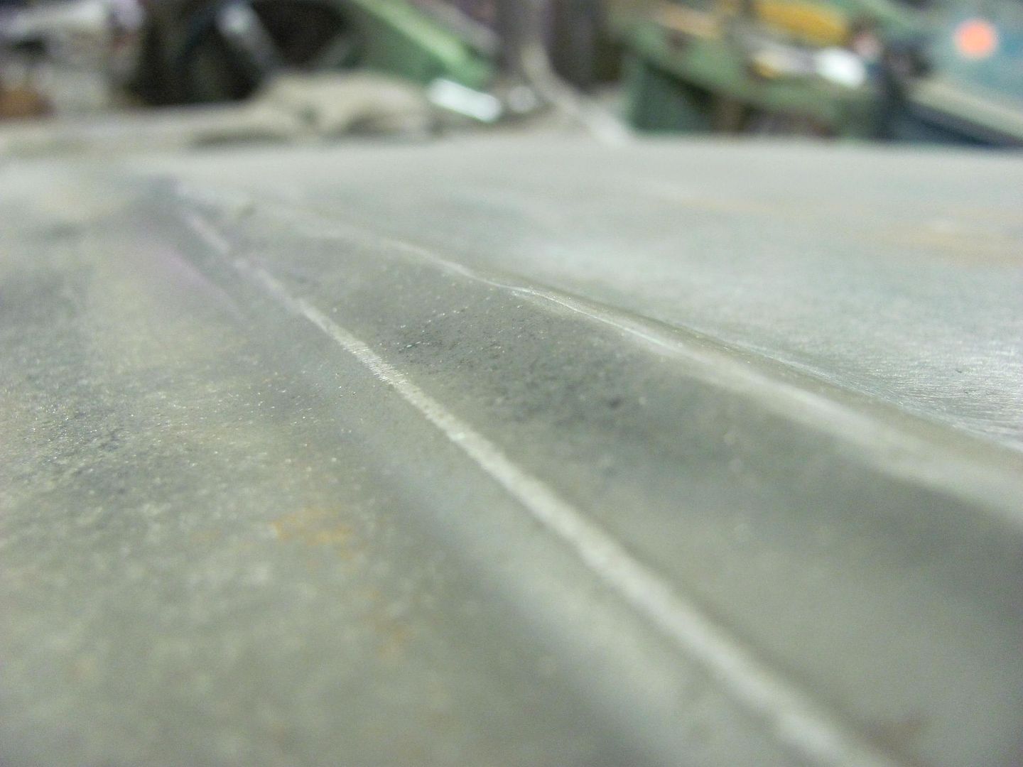
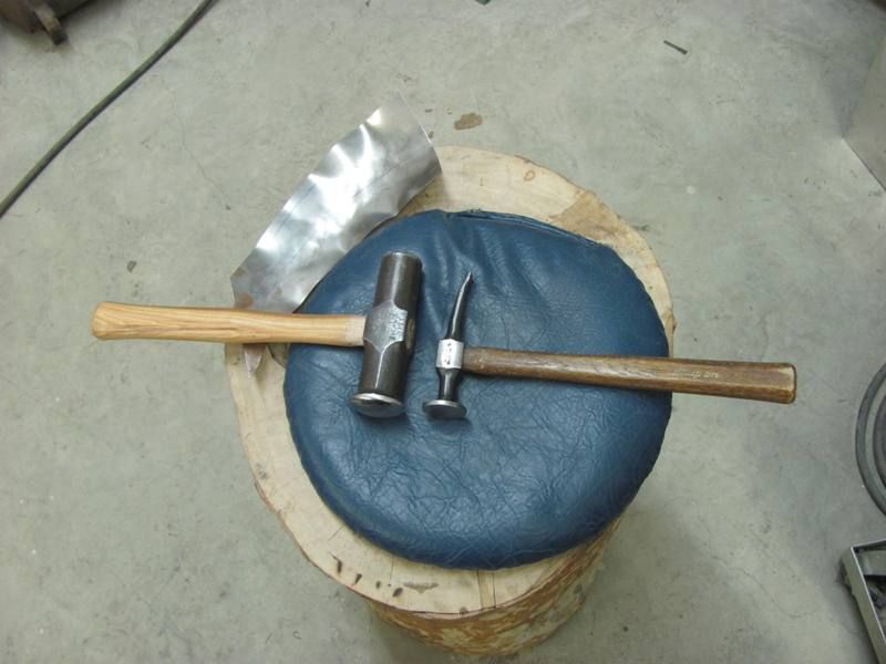
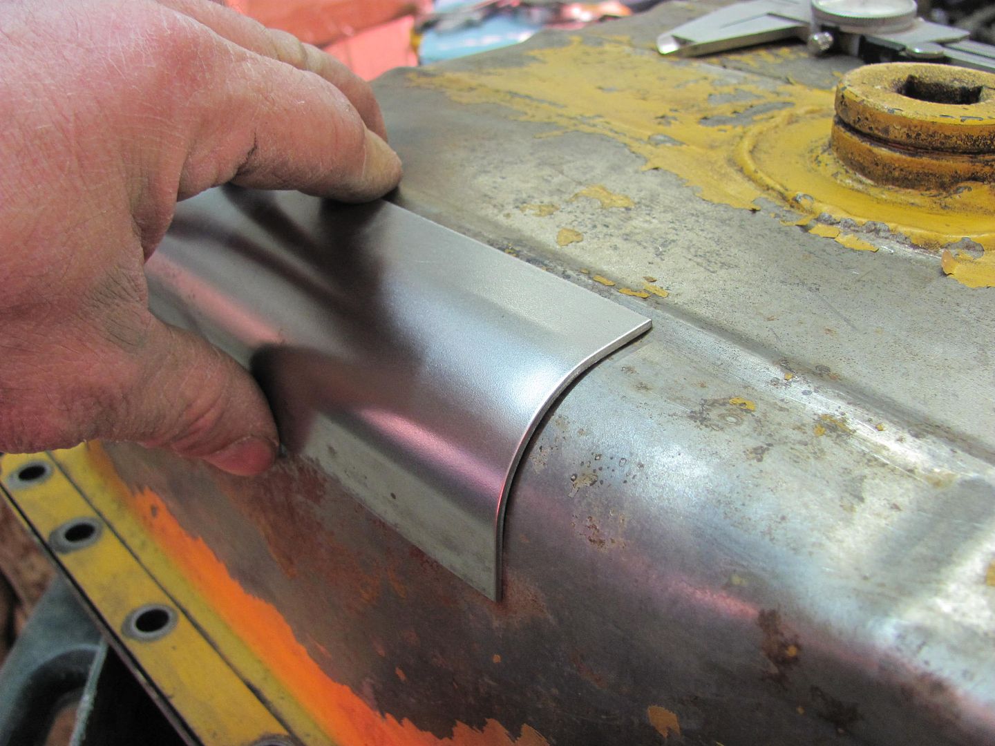
We started with using the crowned body hammer off dolly to knock the sharpness down a bit.

Picture494.jpg


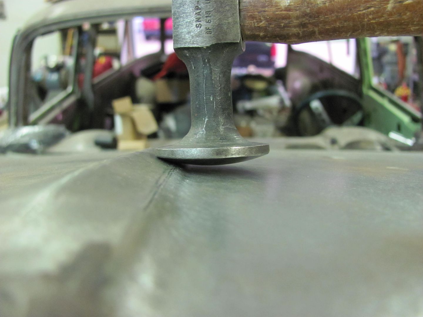
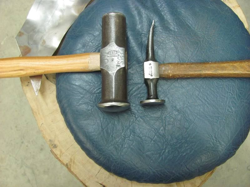
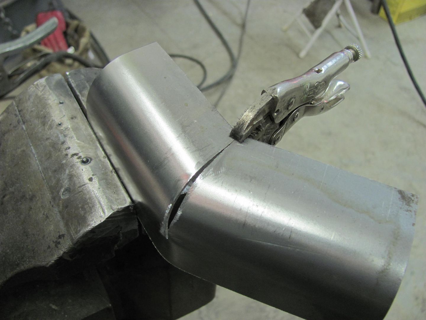
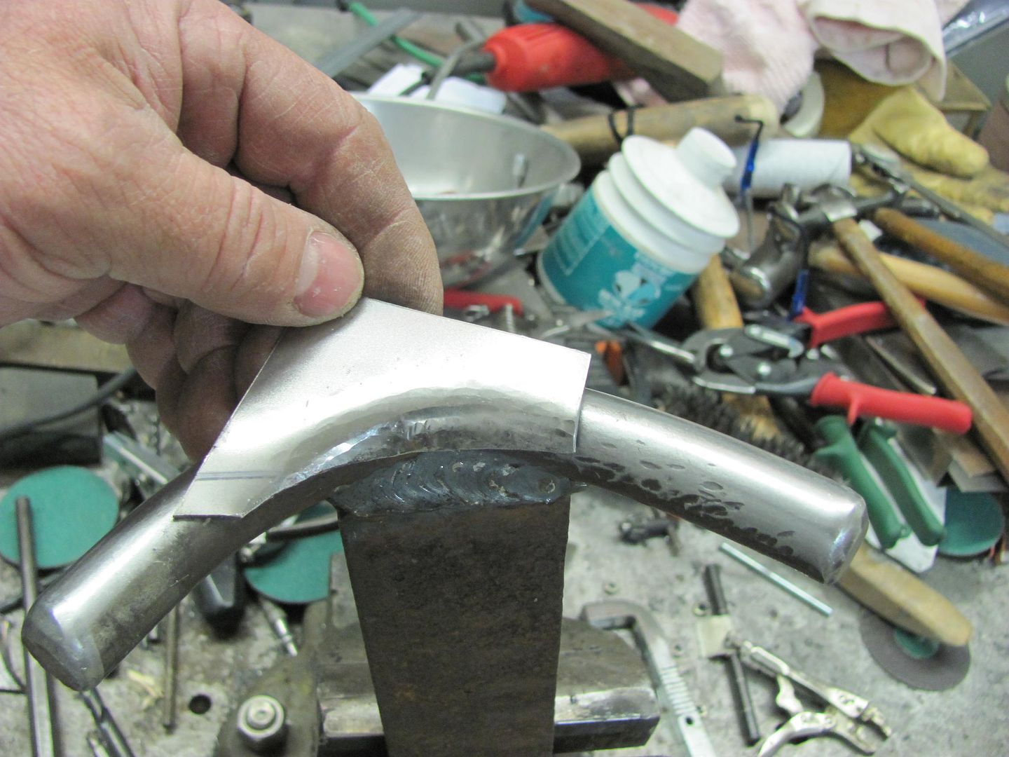
After that we needed something that more closely matched the inside radius. This would work if it weren't for that flat spot on the bottom of the hammer....

Picture495.jpg


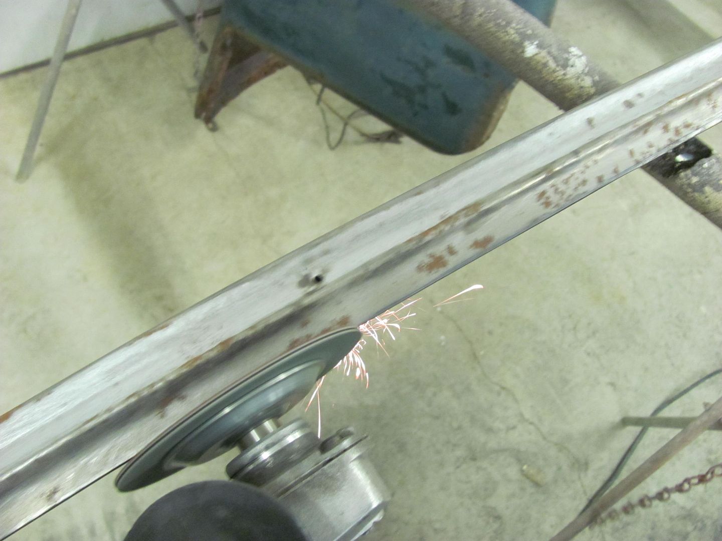
...but after about 5 minutes with the grinder it had a more conforming radius..

Picture496.jpg


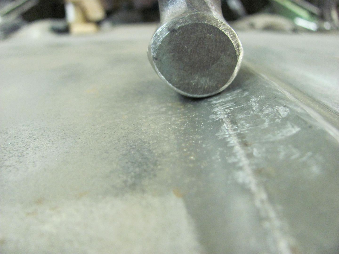
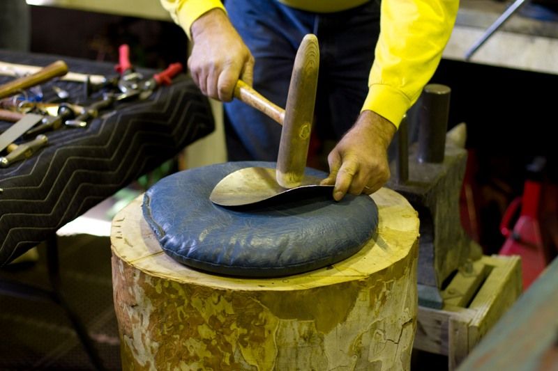
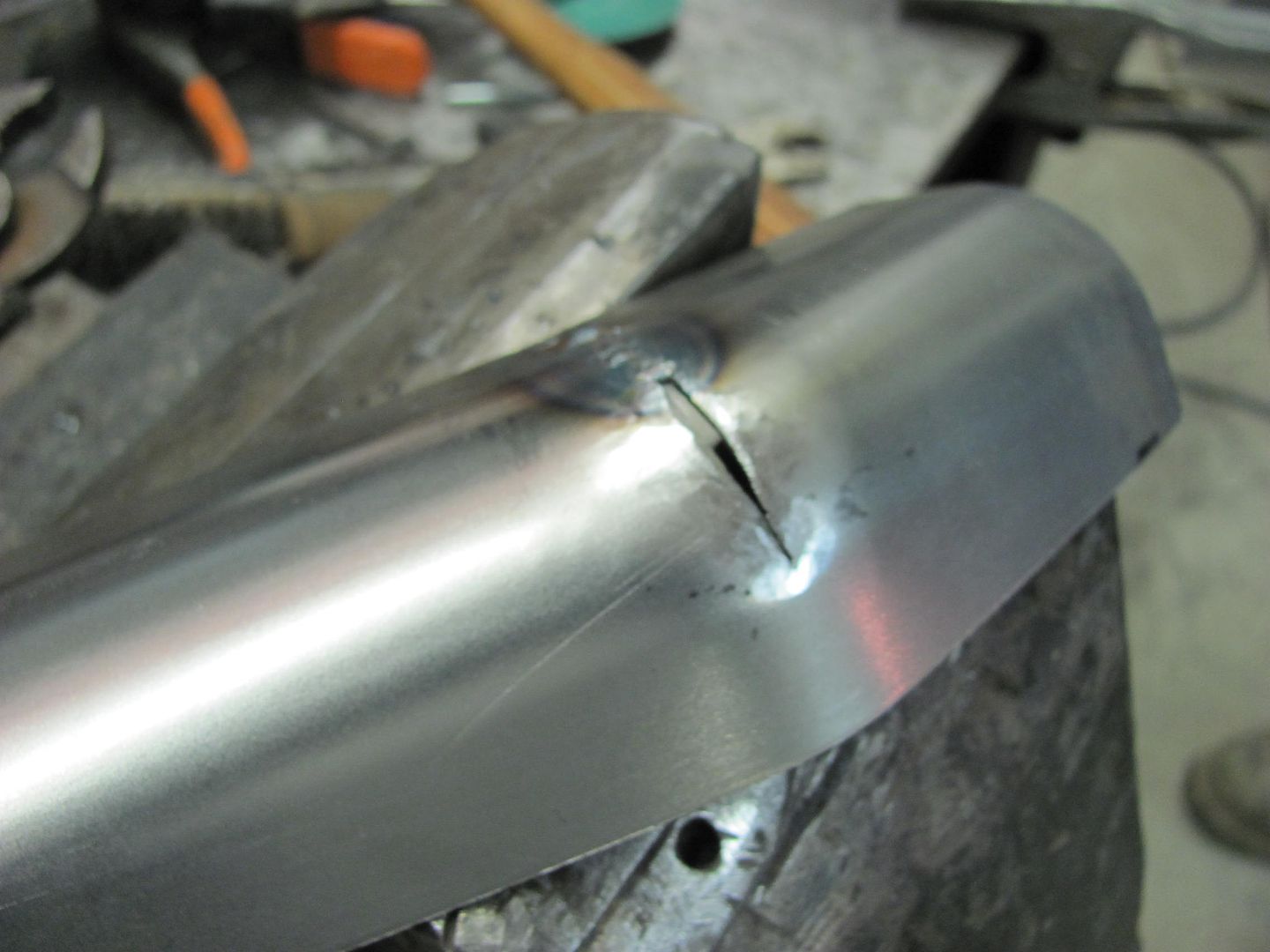
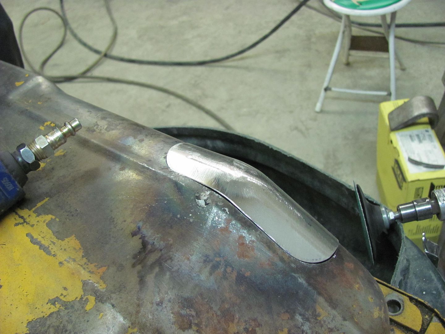
Kept working and working (and more use of the "Punch and Die" as well).....

Picture497.jpg


Picture498.jpg


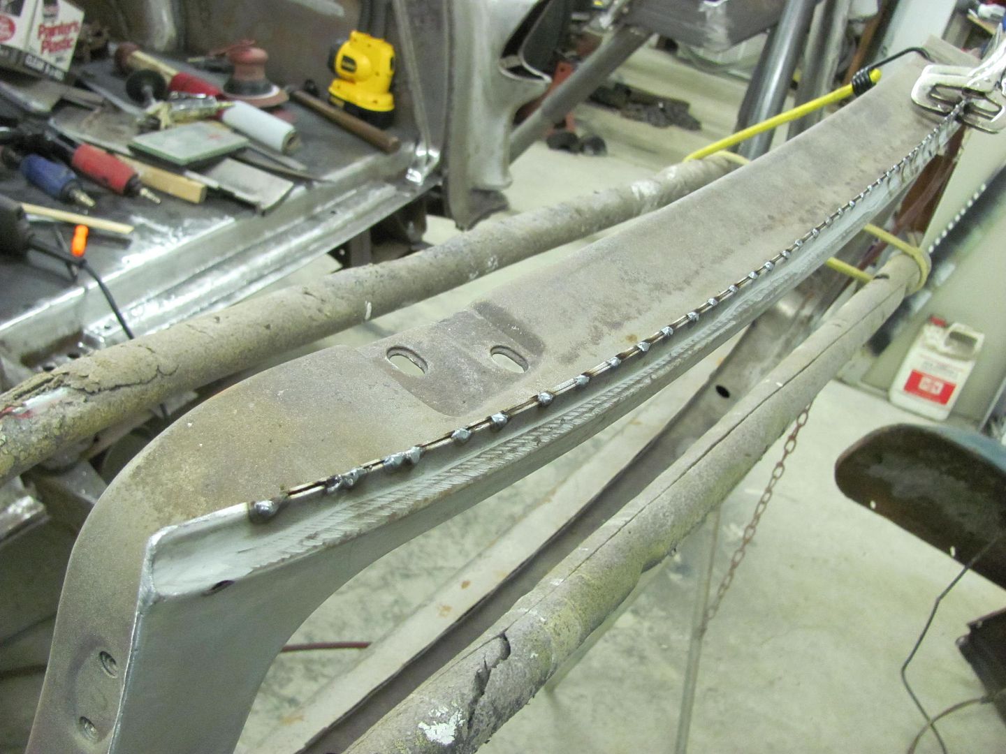
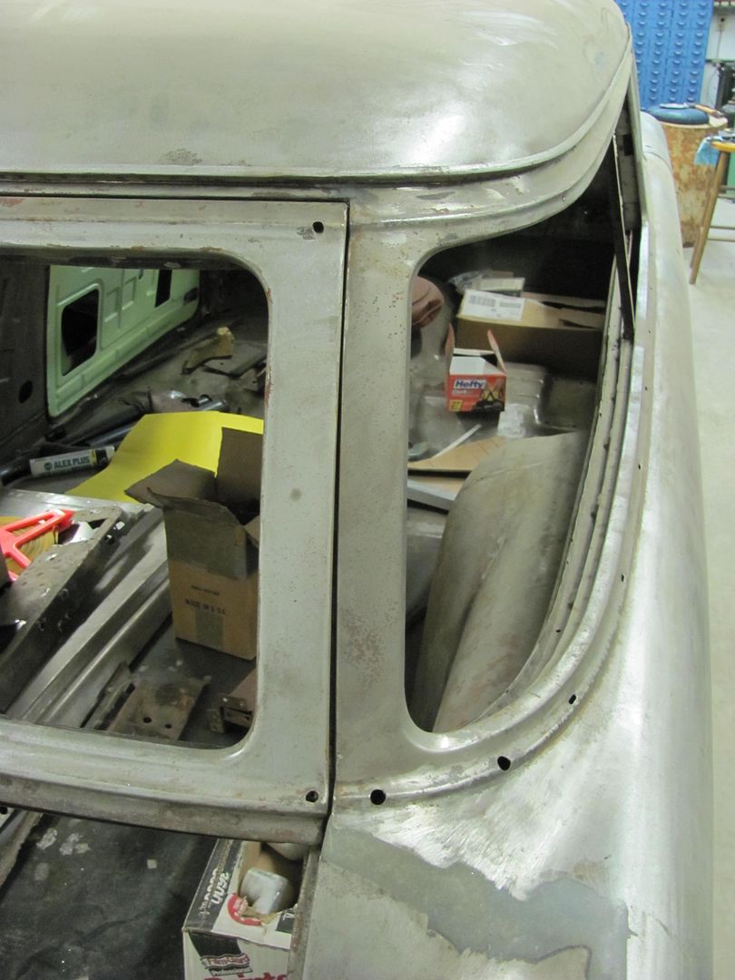
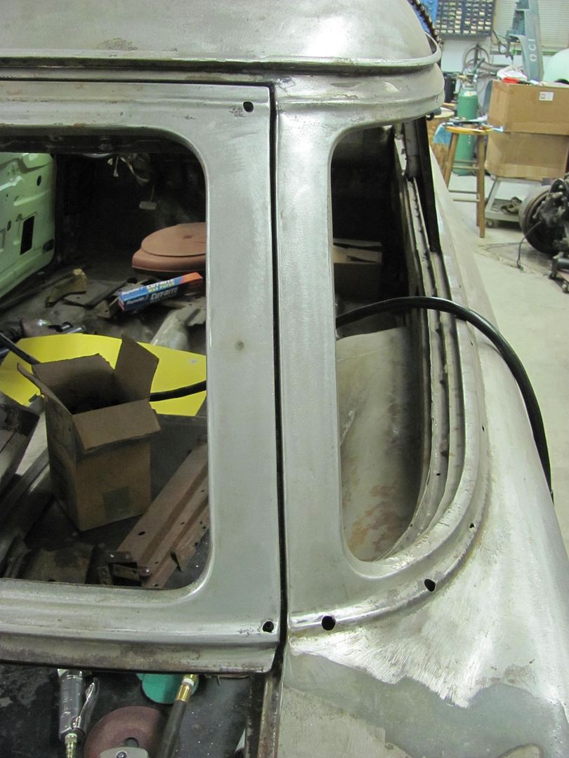
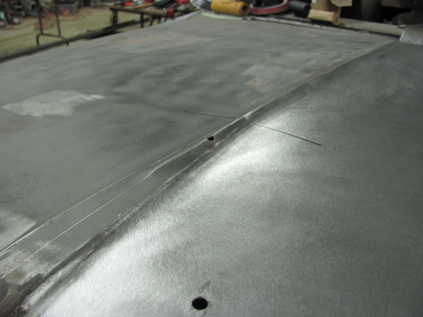
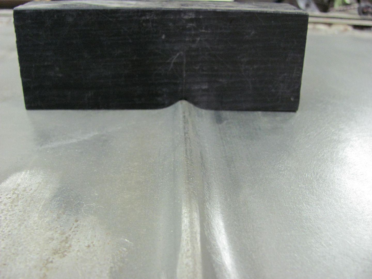
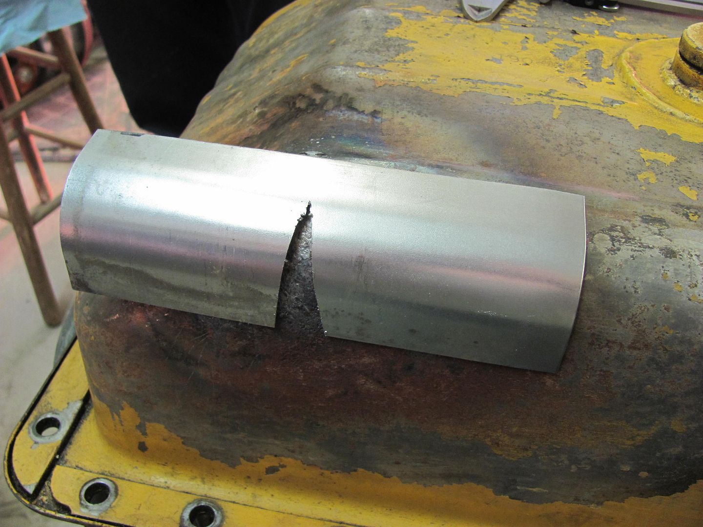
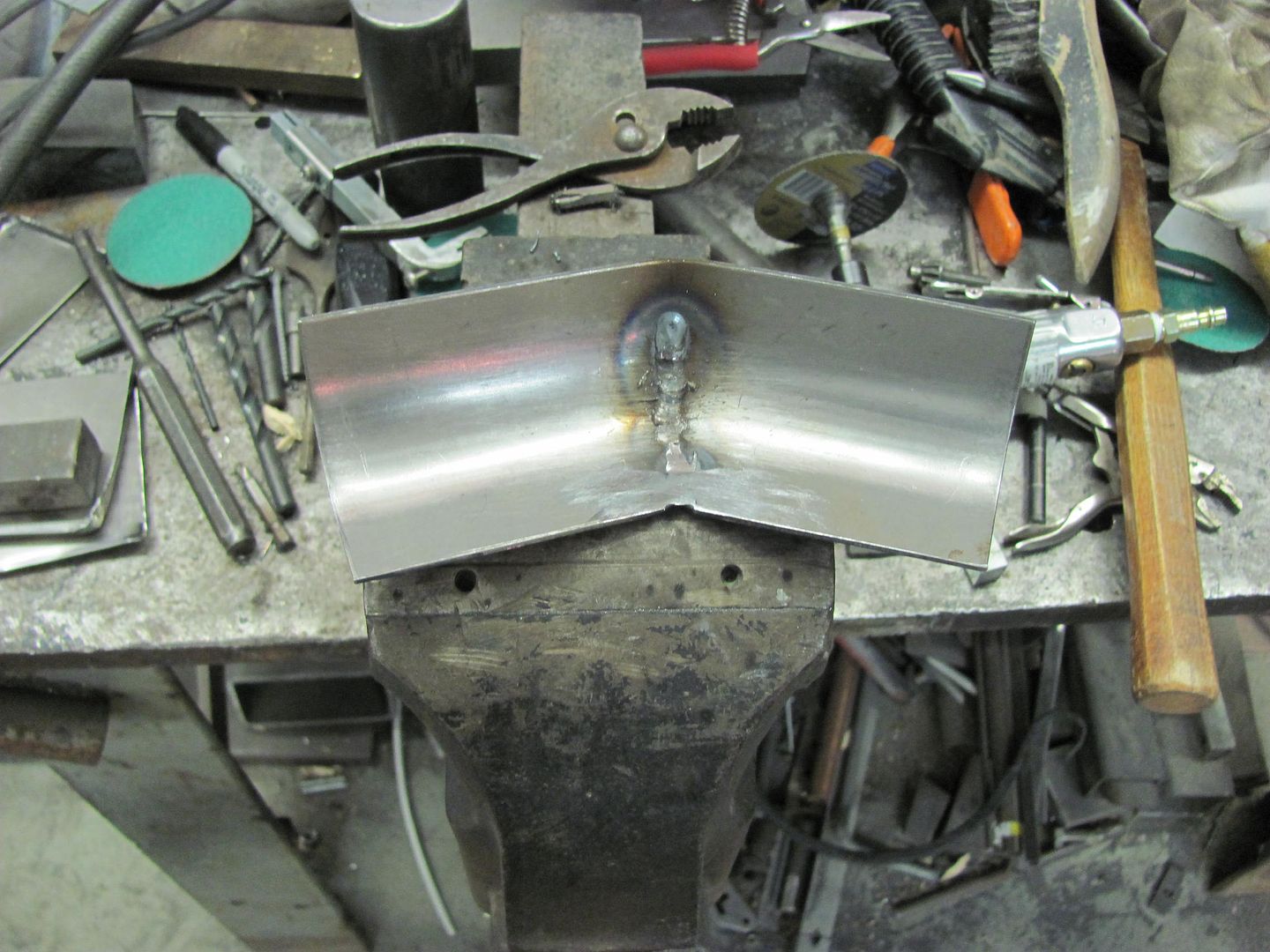
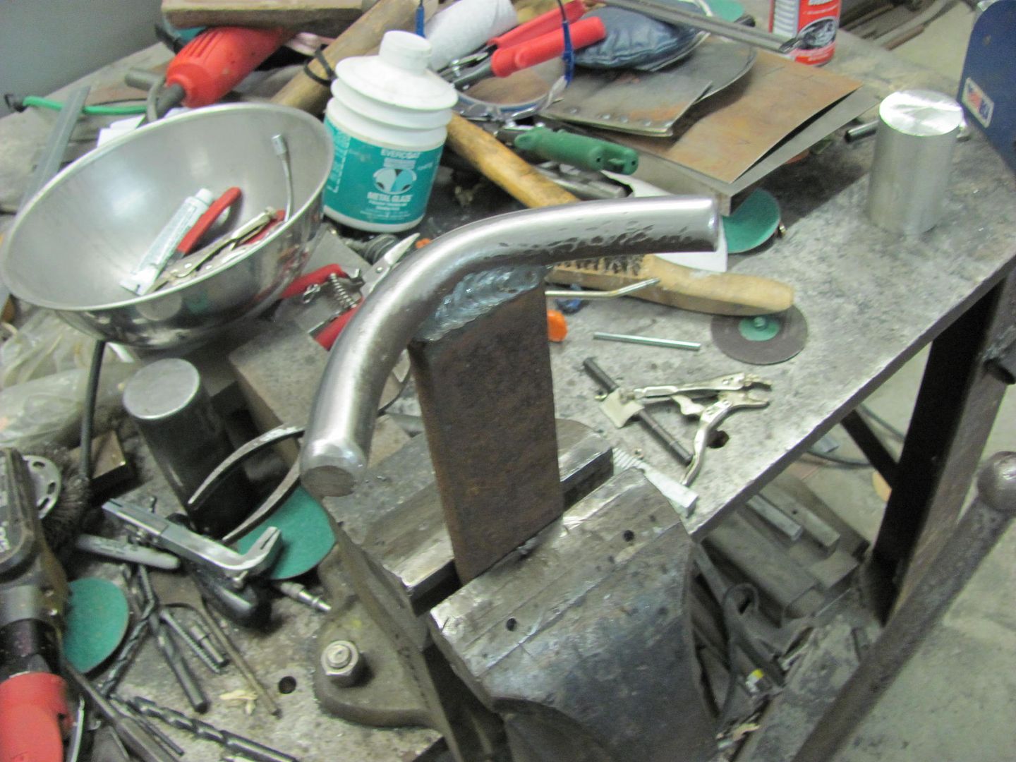
and this is what we ended up with....

Picture499.jpg


Picture500.jpg


Picture501.jpg


Picture503.jpg


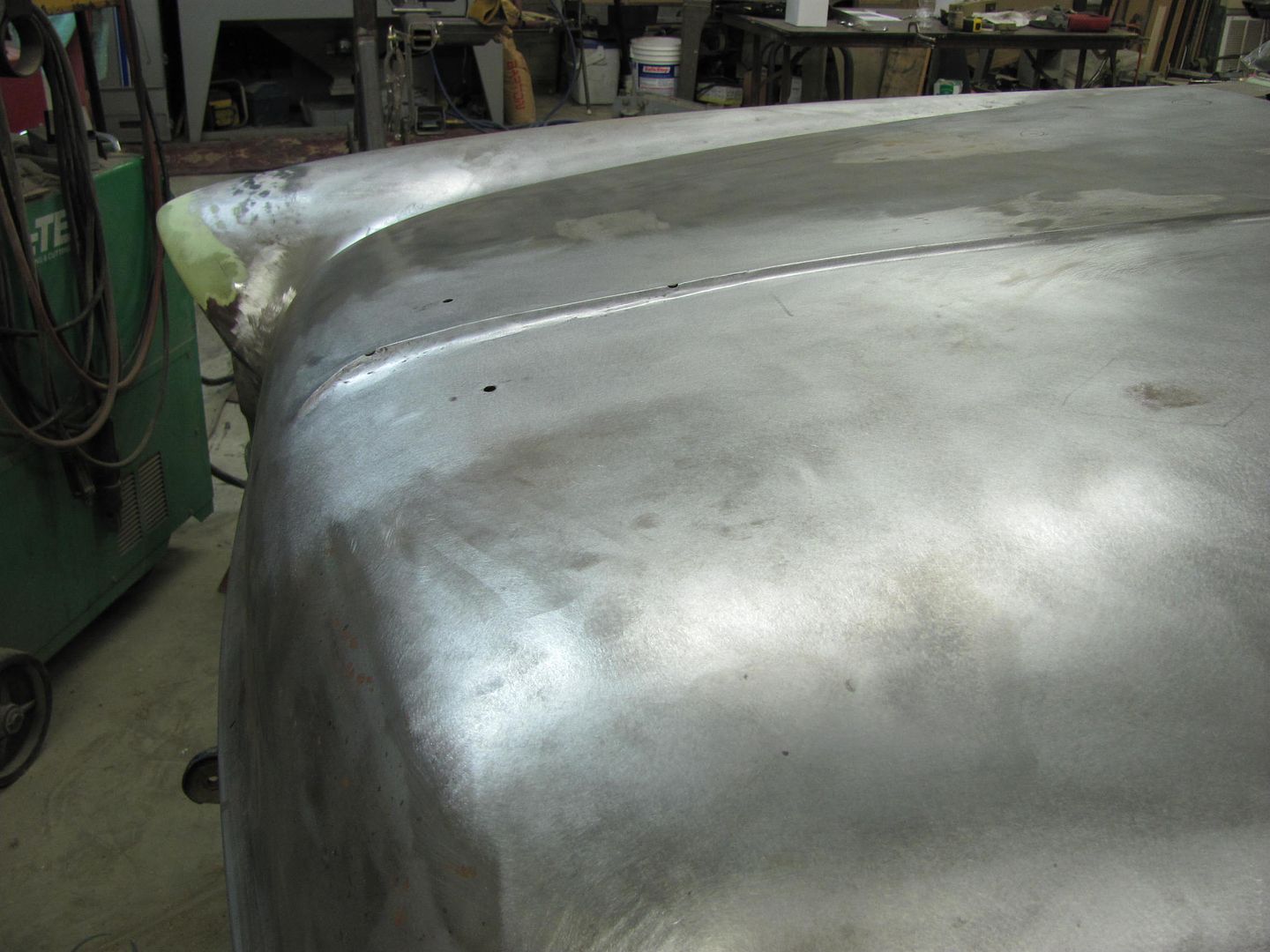
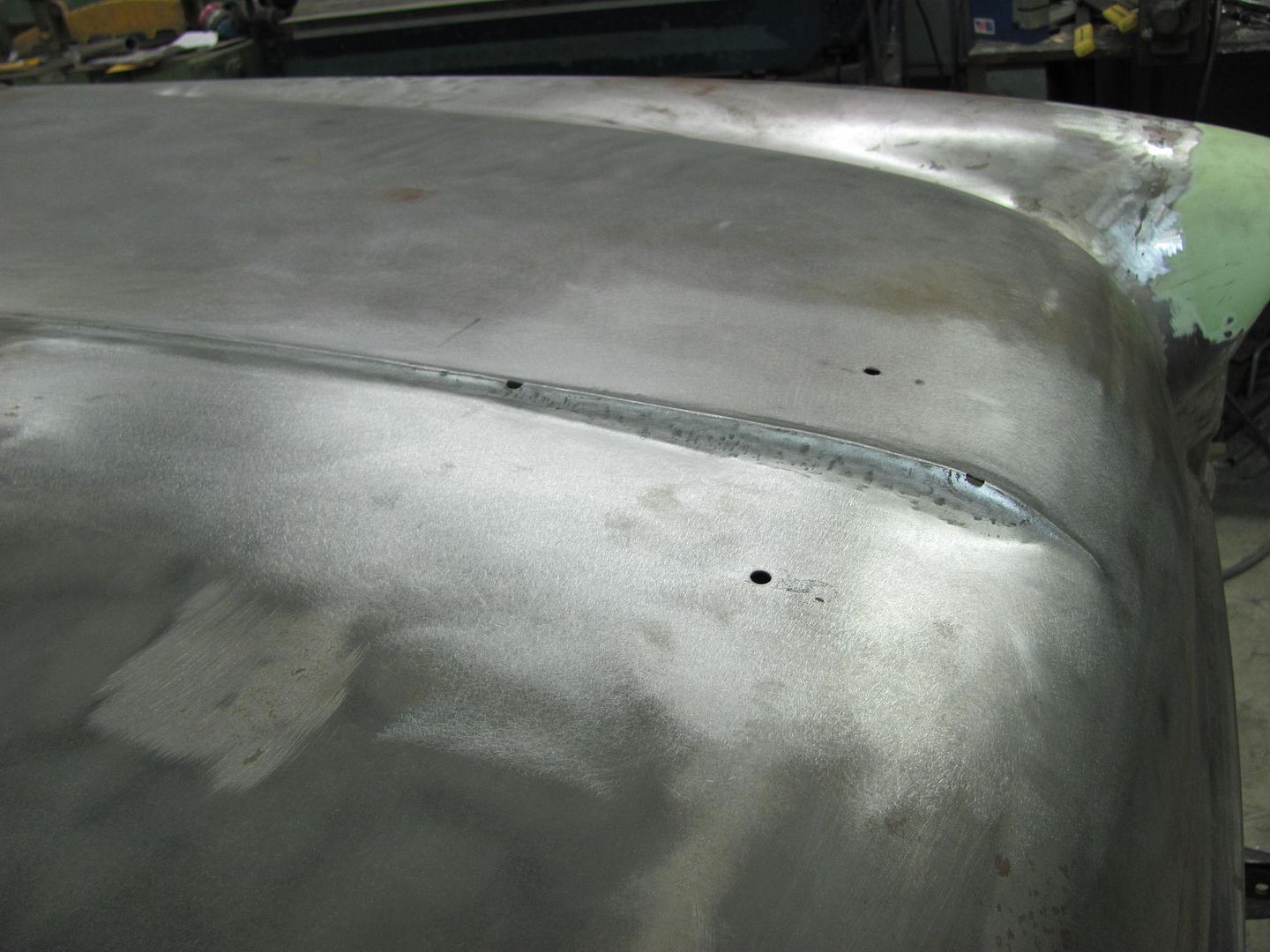
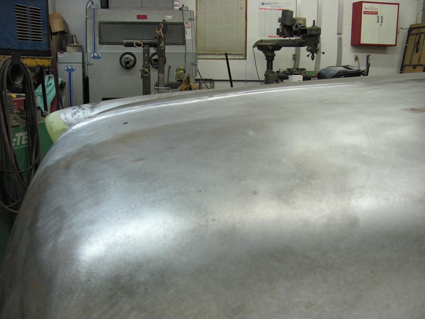
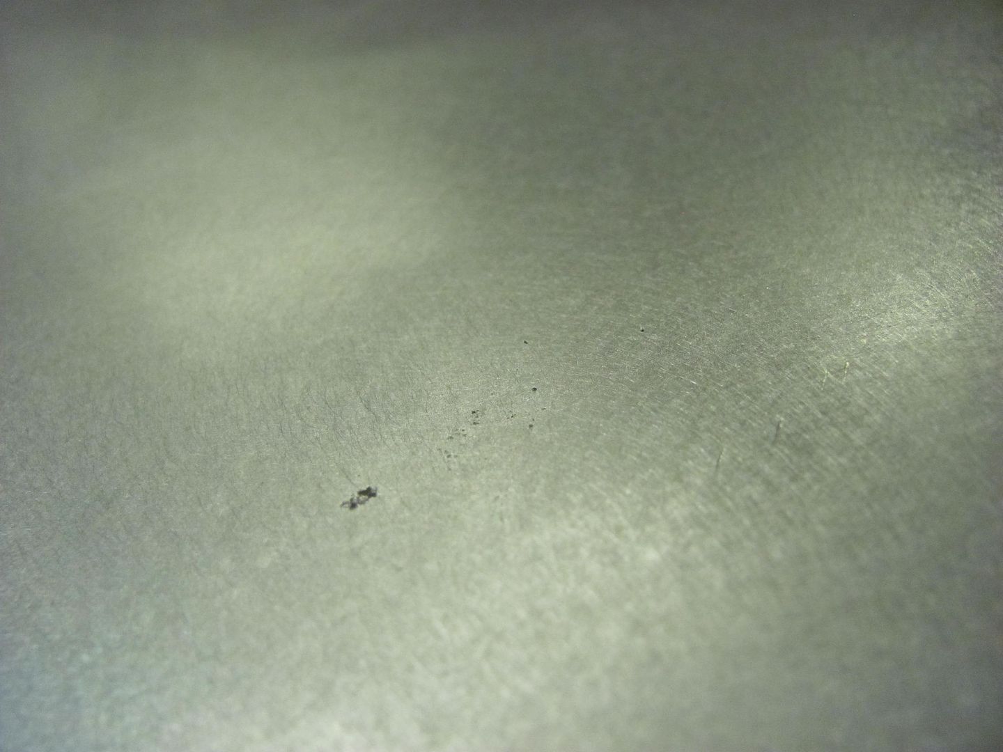
It still has some fine tuning to go, holes to fill, some shrinking in the "valley" down both sides towards the front and some tweaking here and there to make the peak more uniform front to back. But overall I'm real pleased with how it turned out.


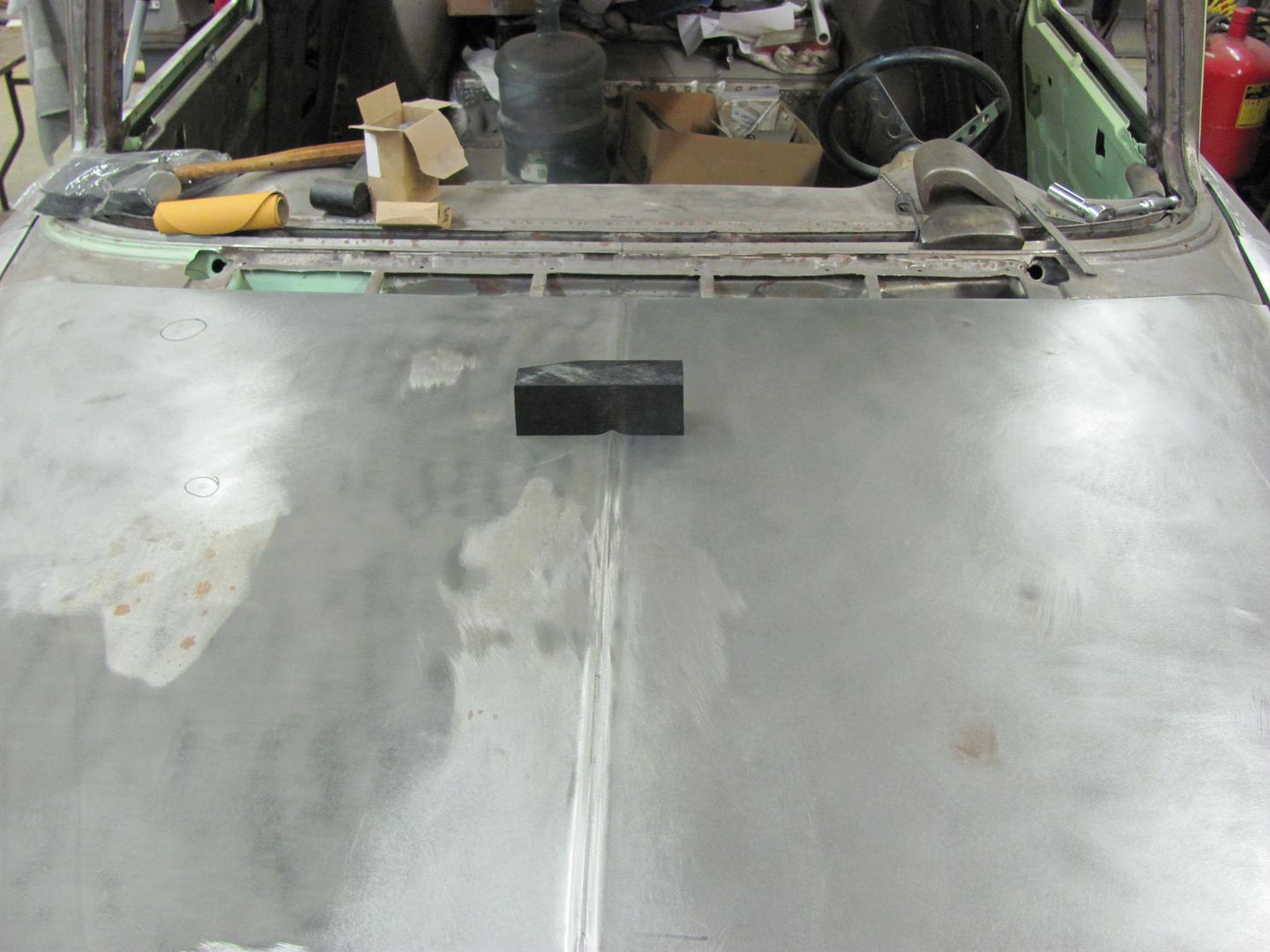
Backing up a second, a few more details.....


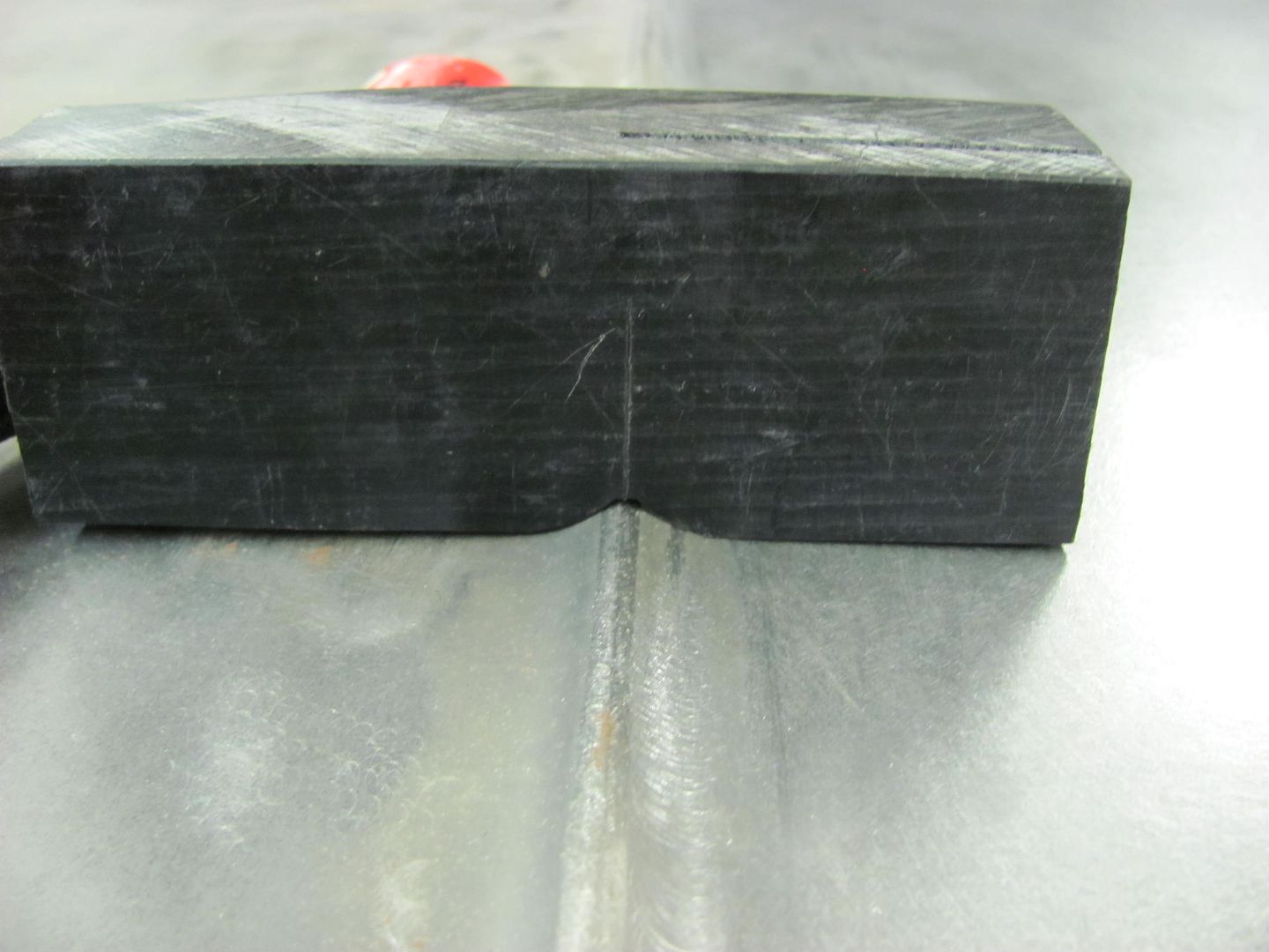
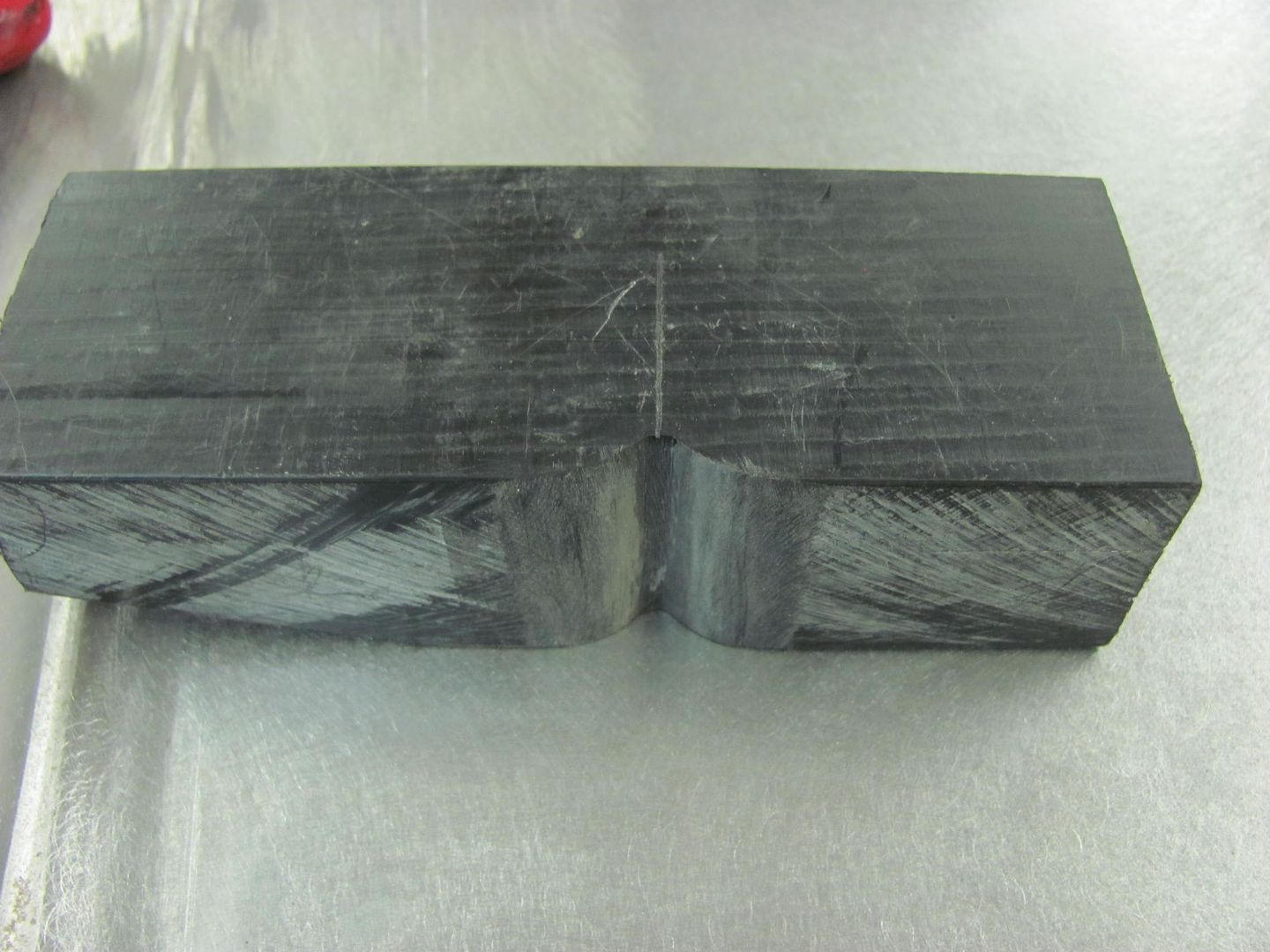
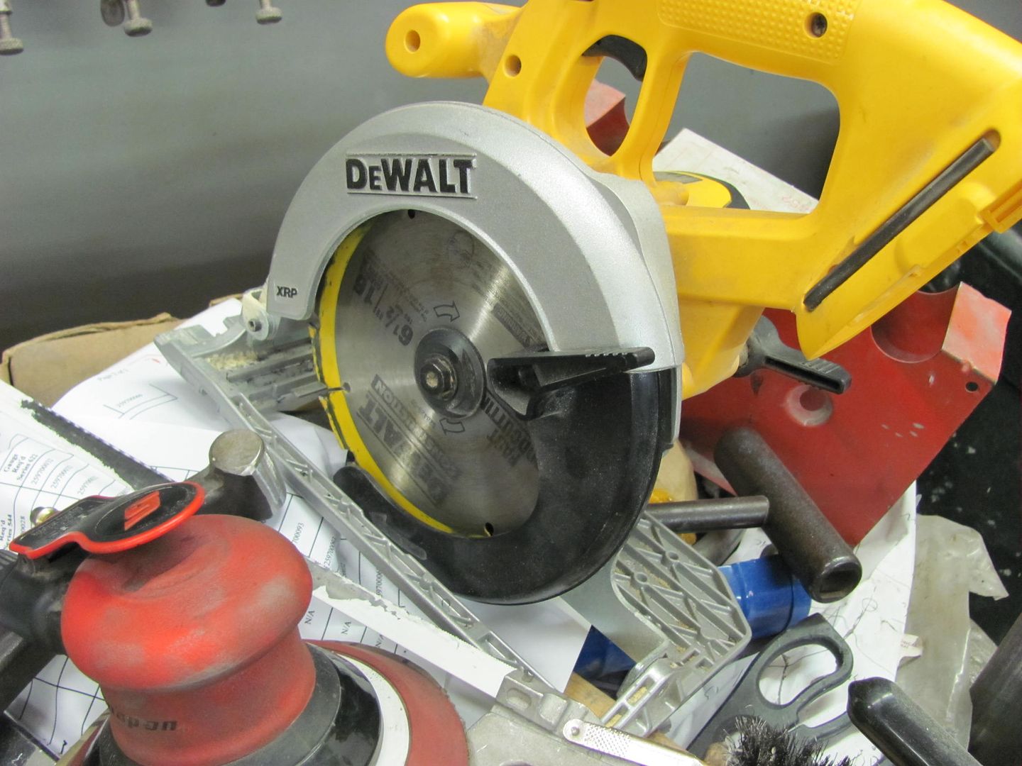
The plastic is a black delrin, it is some pricey stuff so if you know anyone who uses it try to latch on to any scraps for just such an occasion, but this stuff came from McMaster Carr. I have also used it for making a non-marring "punch" for persuading some stainless moulding into moving where I wanted it to. I believe it is in the Teflon family. It was made using the Dewalt, two passes at about 1/4" deep. The rest of the shape was using an 80grit 3" roloc. Shape, test fit, repeat. (Until it matched the peak on the rear part of the hood)

Picture511.jpg


Picture512.jpg


An alignment mark was located on the delrin "die" and down the center of the hood, and also on the underside for keeping the punch in line. Very much a two person operation, good thing my nephew Chris needed some money for a transmission ;) (dang Honda'a) or this might have been a weld caper.


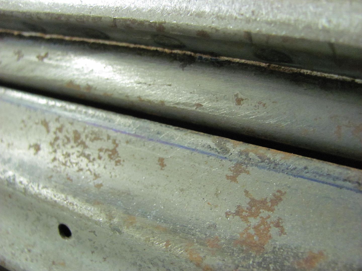
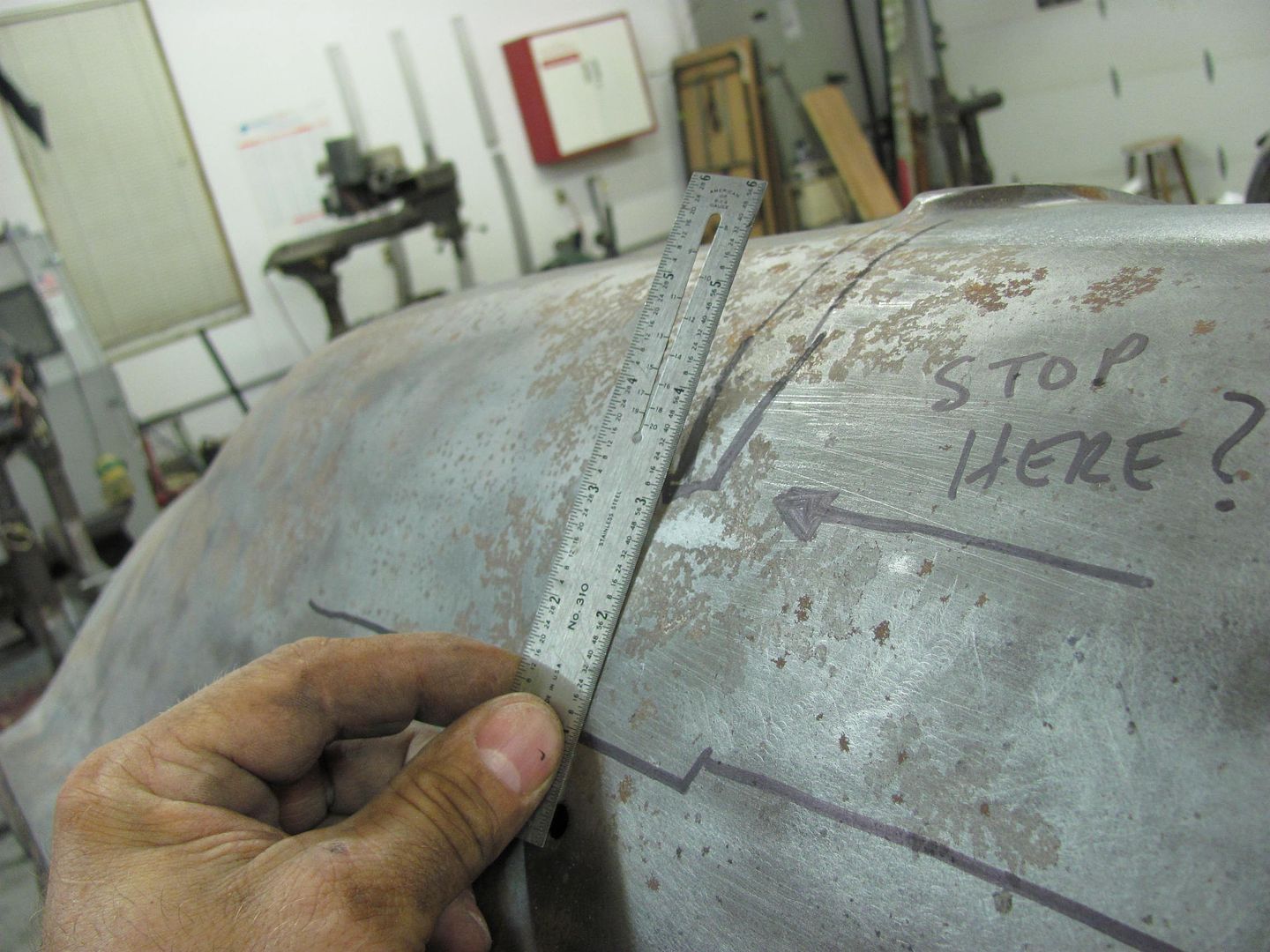
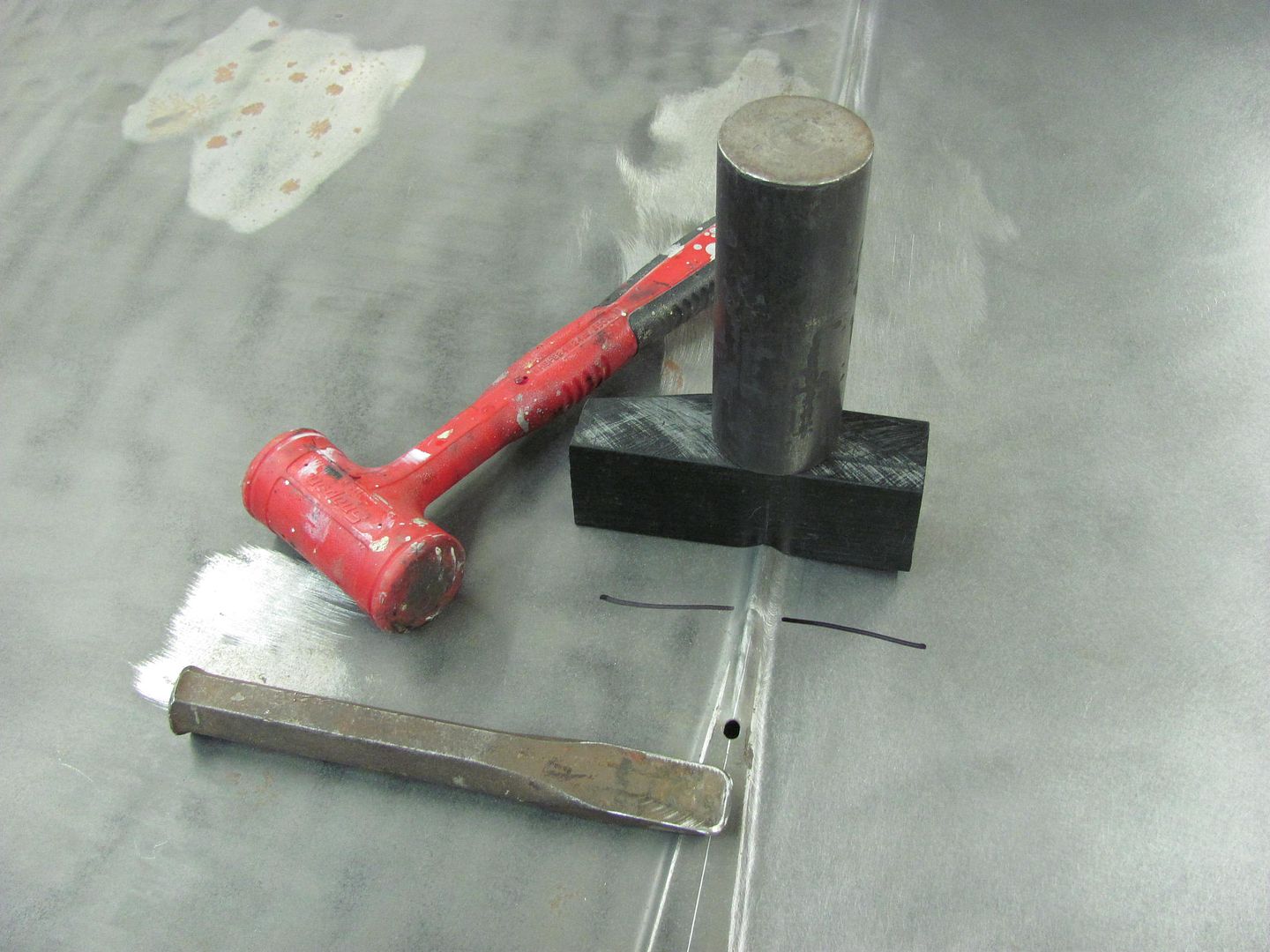
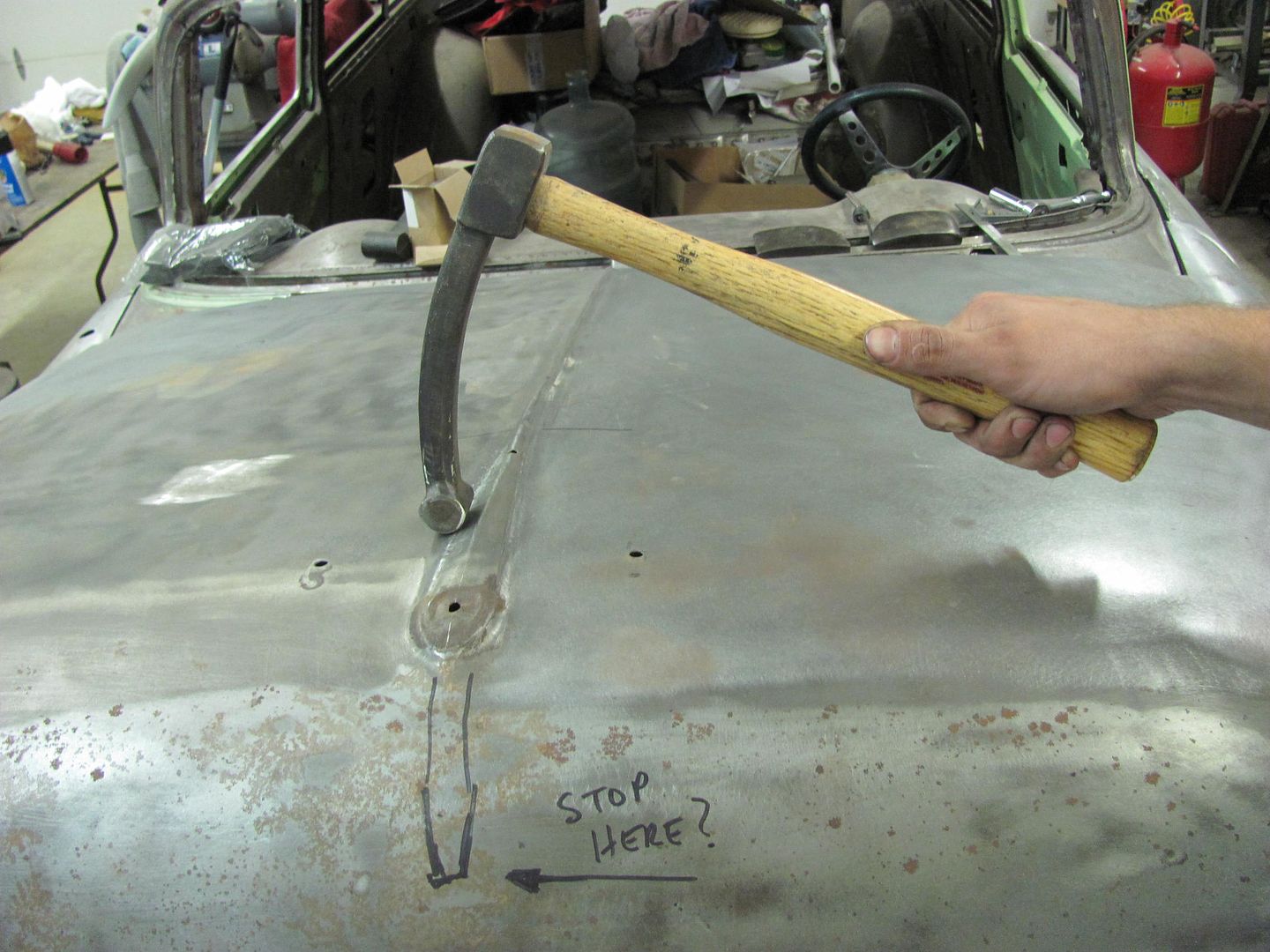
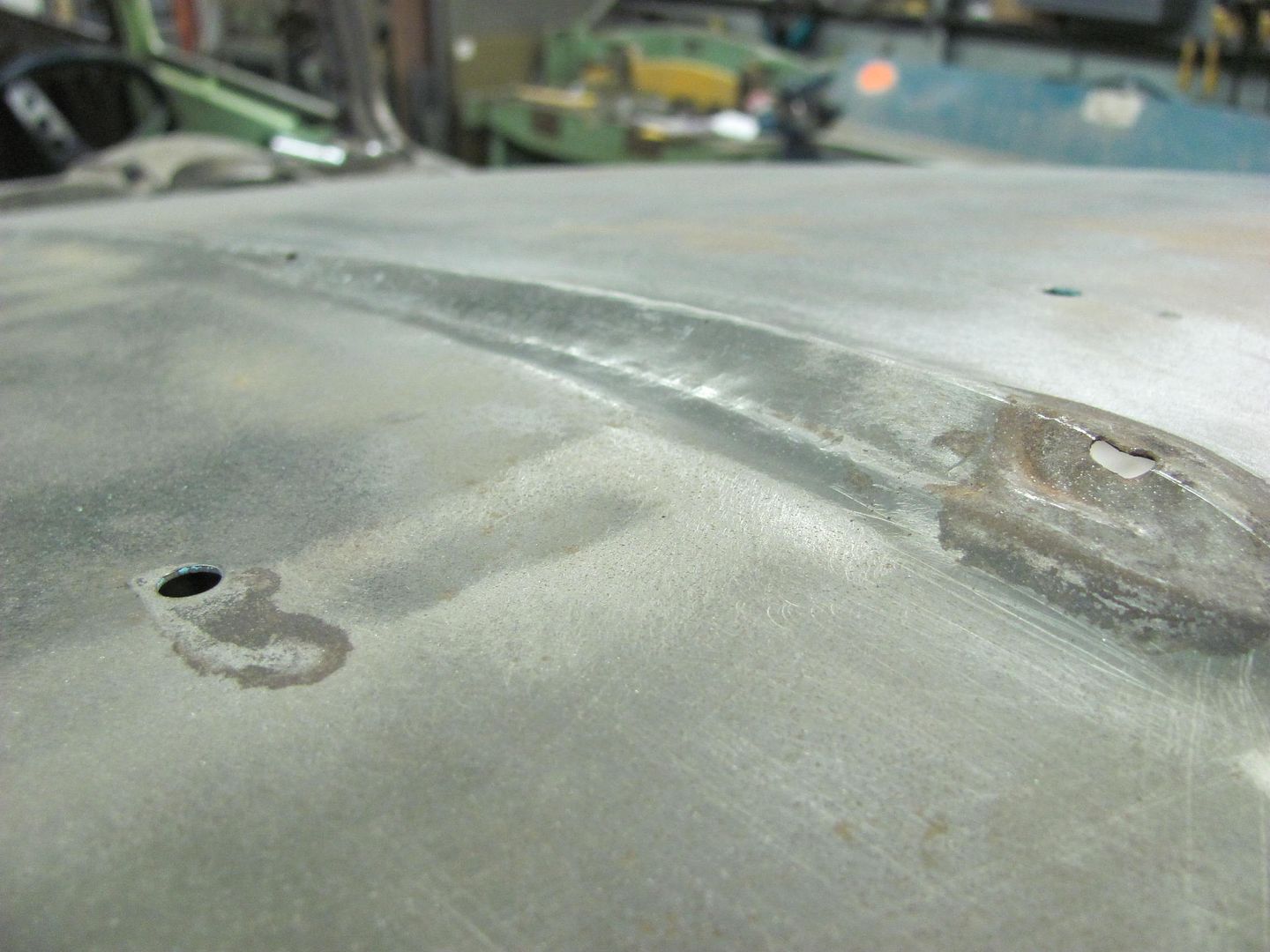
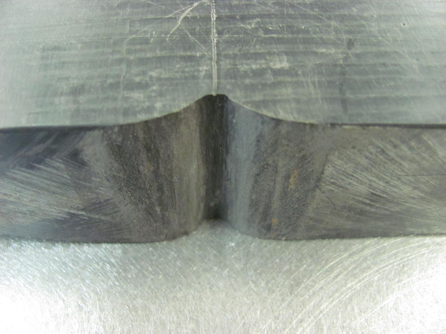
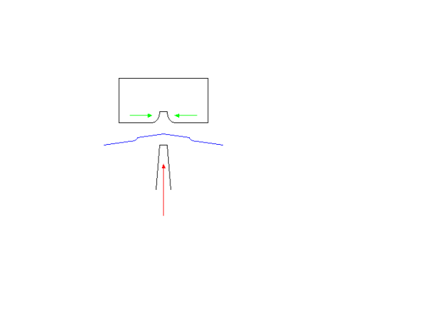
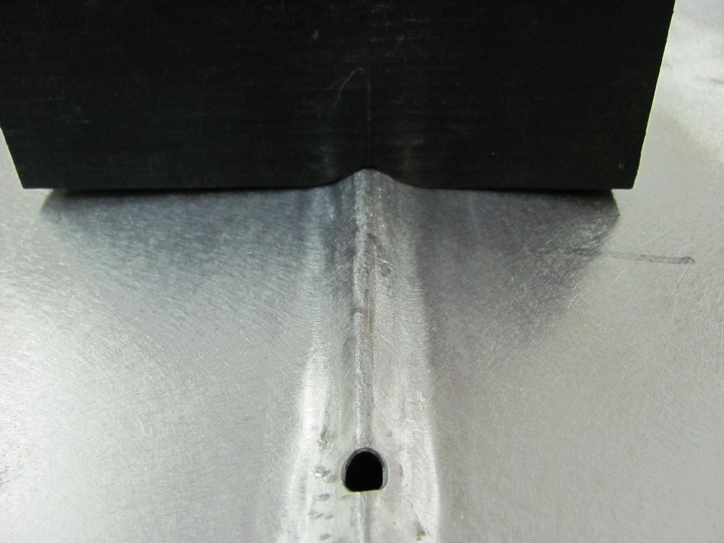
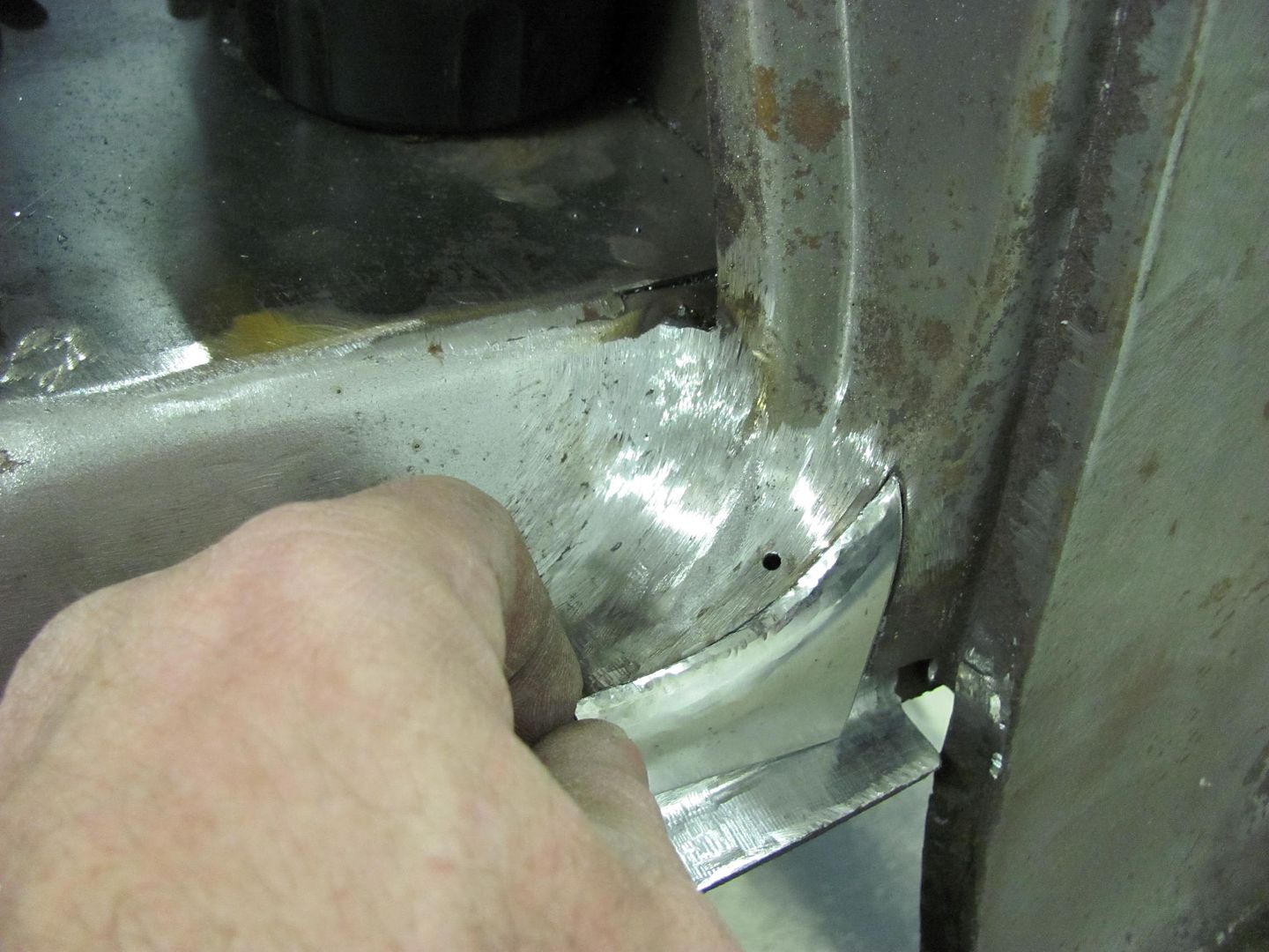
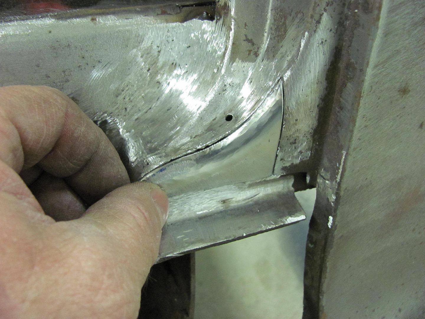
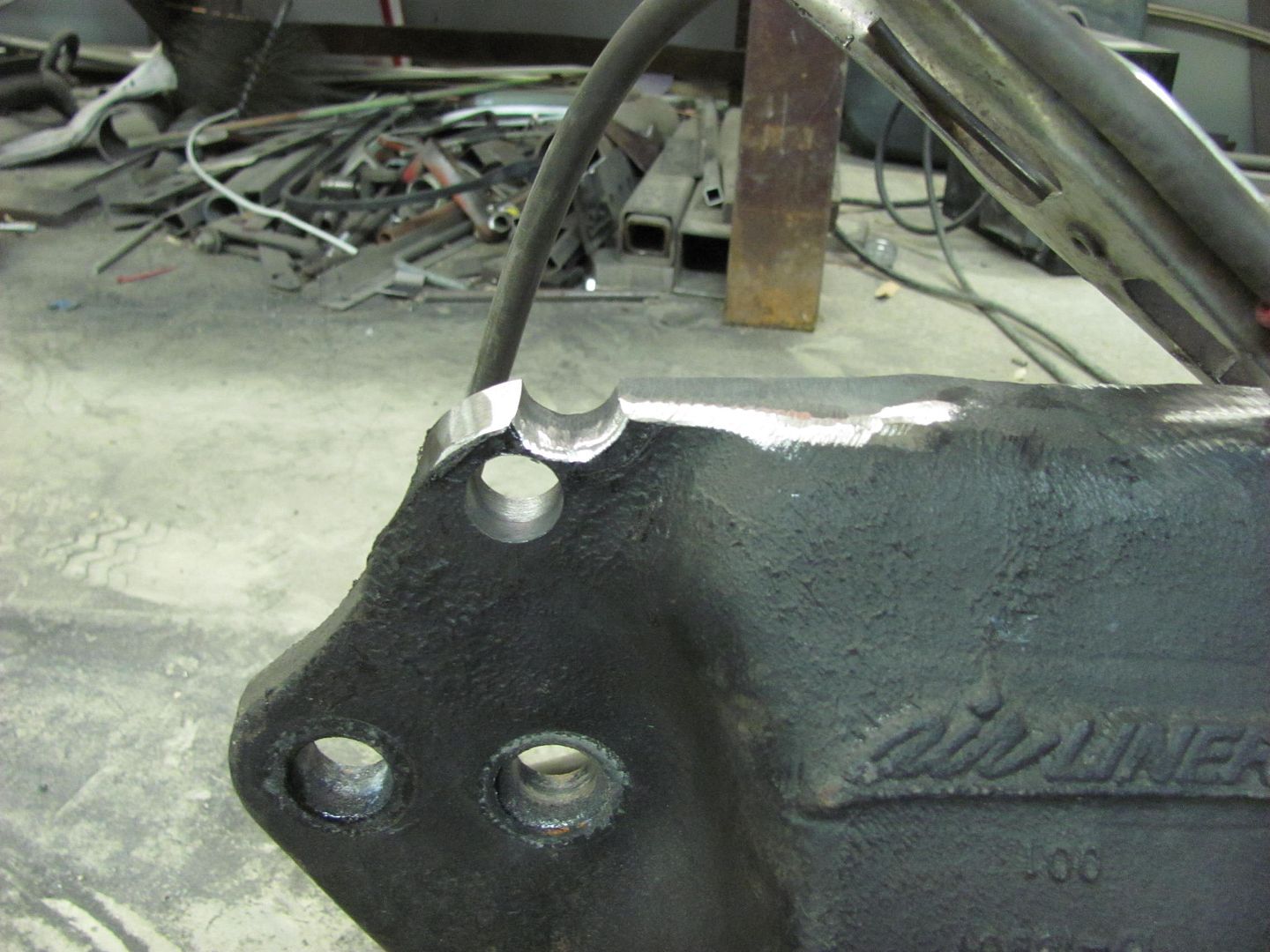
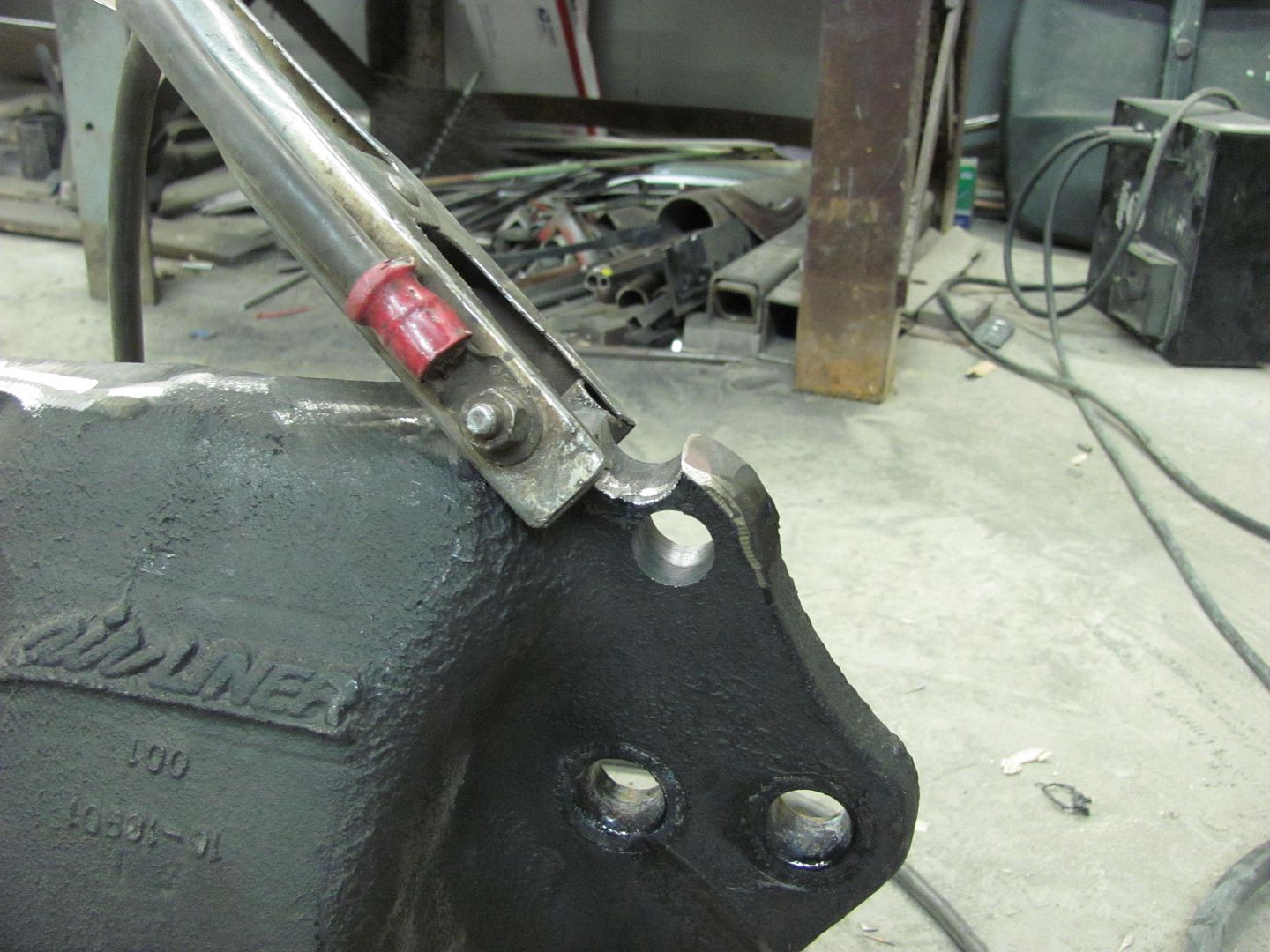
The Delrin, although a hard plastic, tends to absorb the "blow" much more than if made of metal, so it will tend to do more shaping and shrinking rather than stretching had it been metal. The 2" round stock in the photos (above post) was merely to keep the delrin from bouncing around. Also working in your favor using the punch and die arrangement, after having knocked down the sharp edge of the plateau, as seen in the next picture, operation of the punch (red arrow) will tend to draw the hood in from the sides (green arrows), very much an off-dolly operation. So all in all there should be minimal if any stretching of the panel.

Picture513.png


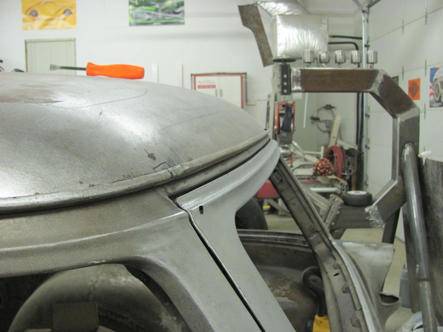
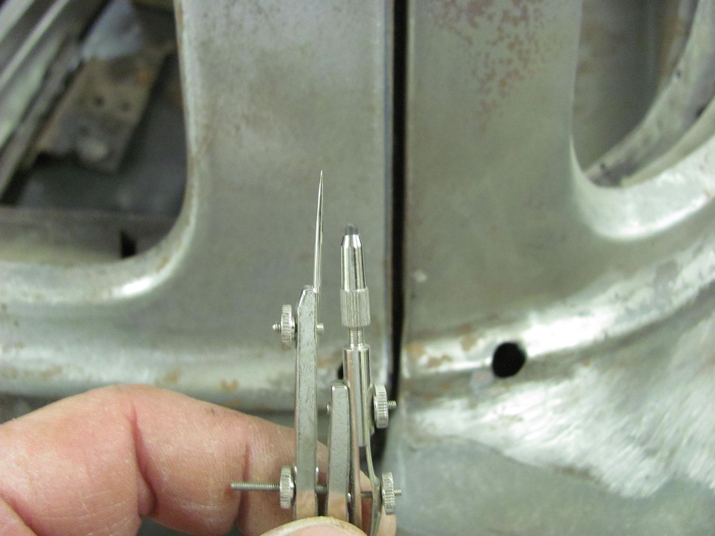
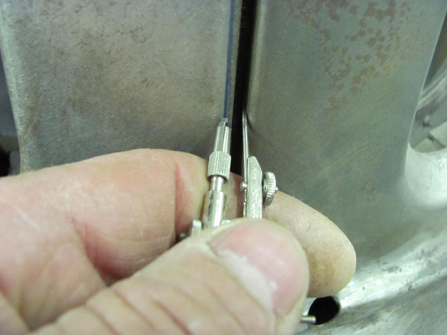
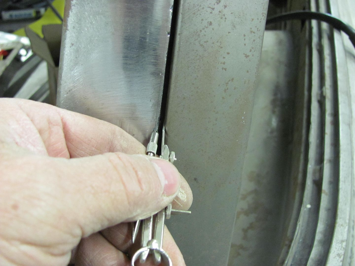
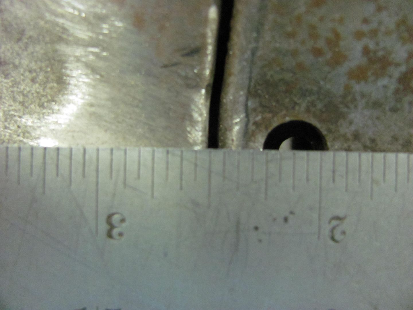
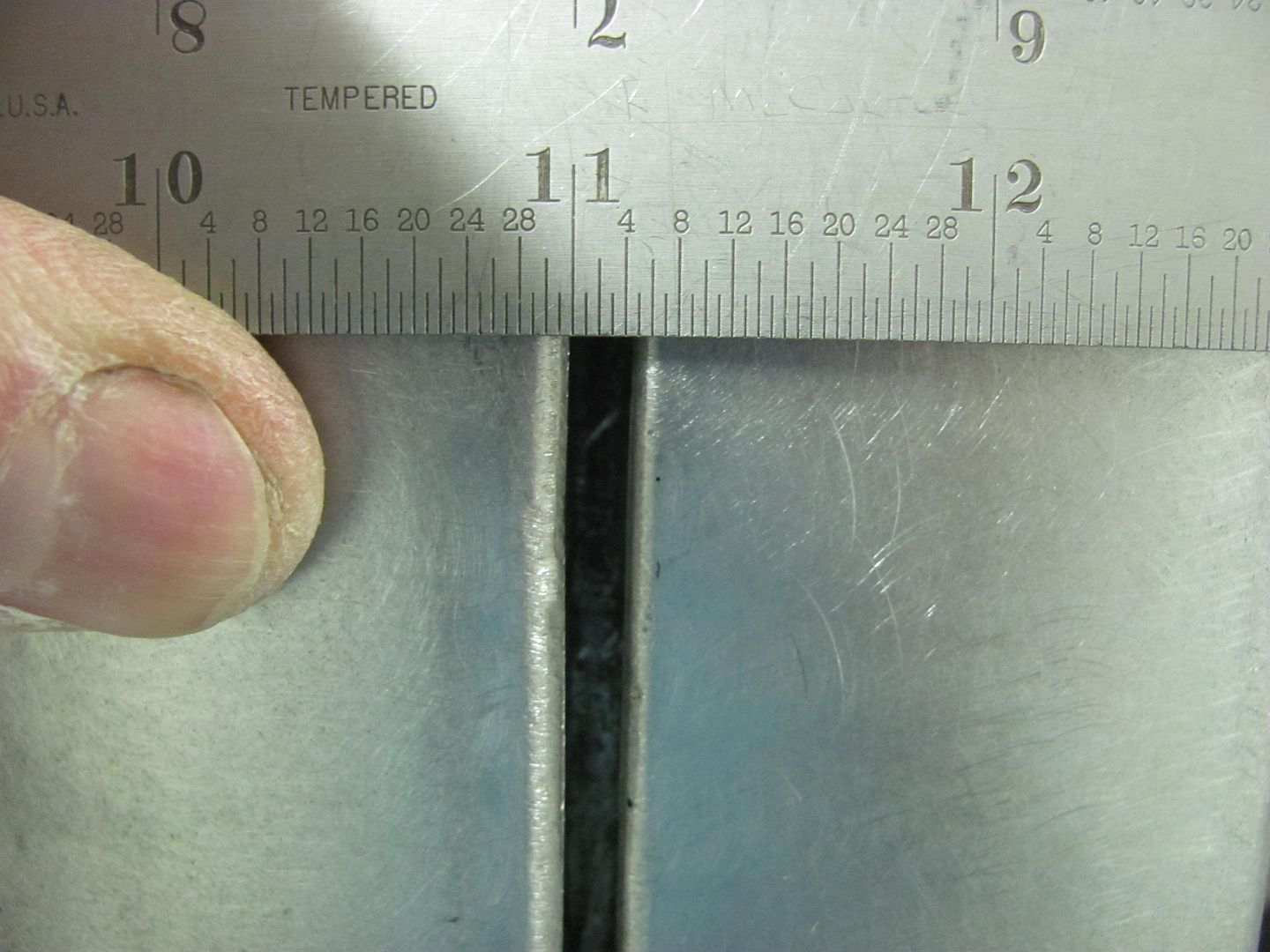
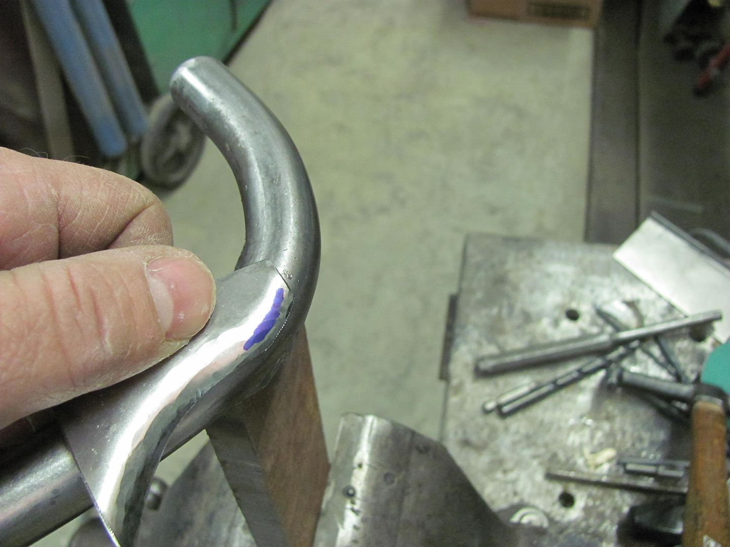
Here are comparisons of the delrin at the rear (factory peak), middle and front of the hood.

Picture505.jpg


Picture506.jpg


Picture507.jpg


Picture508.jpg


Picture509.jpg


Picture510.jpg


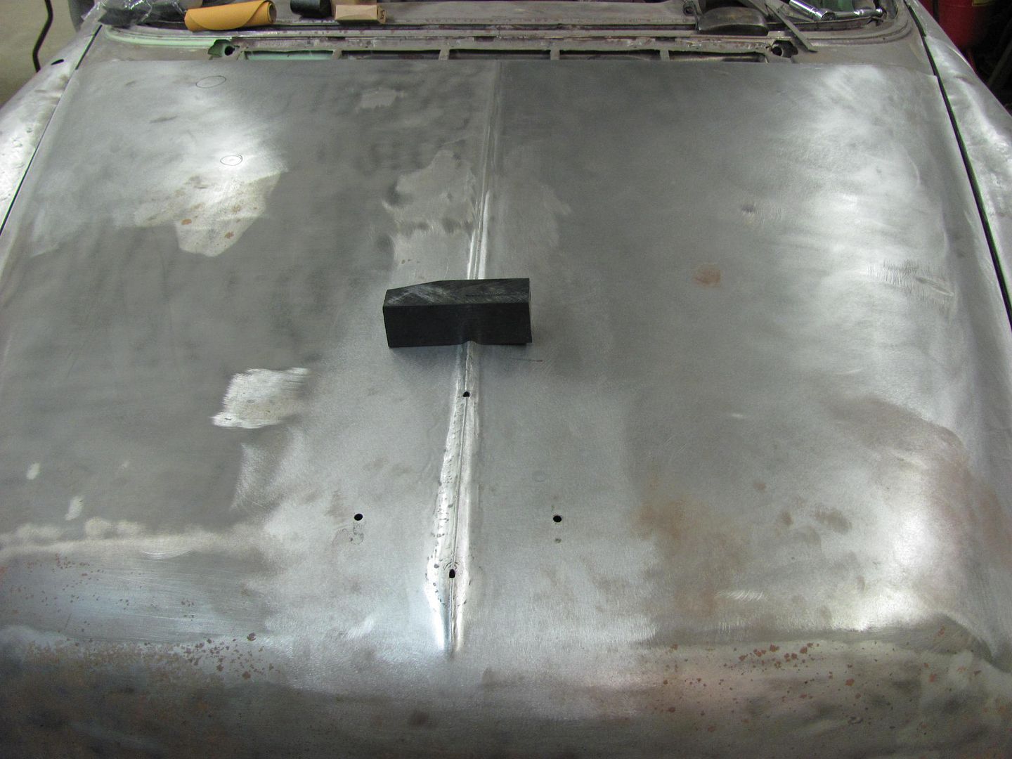
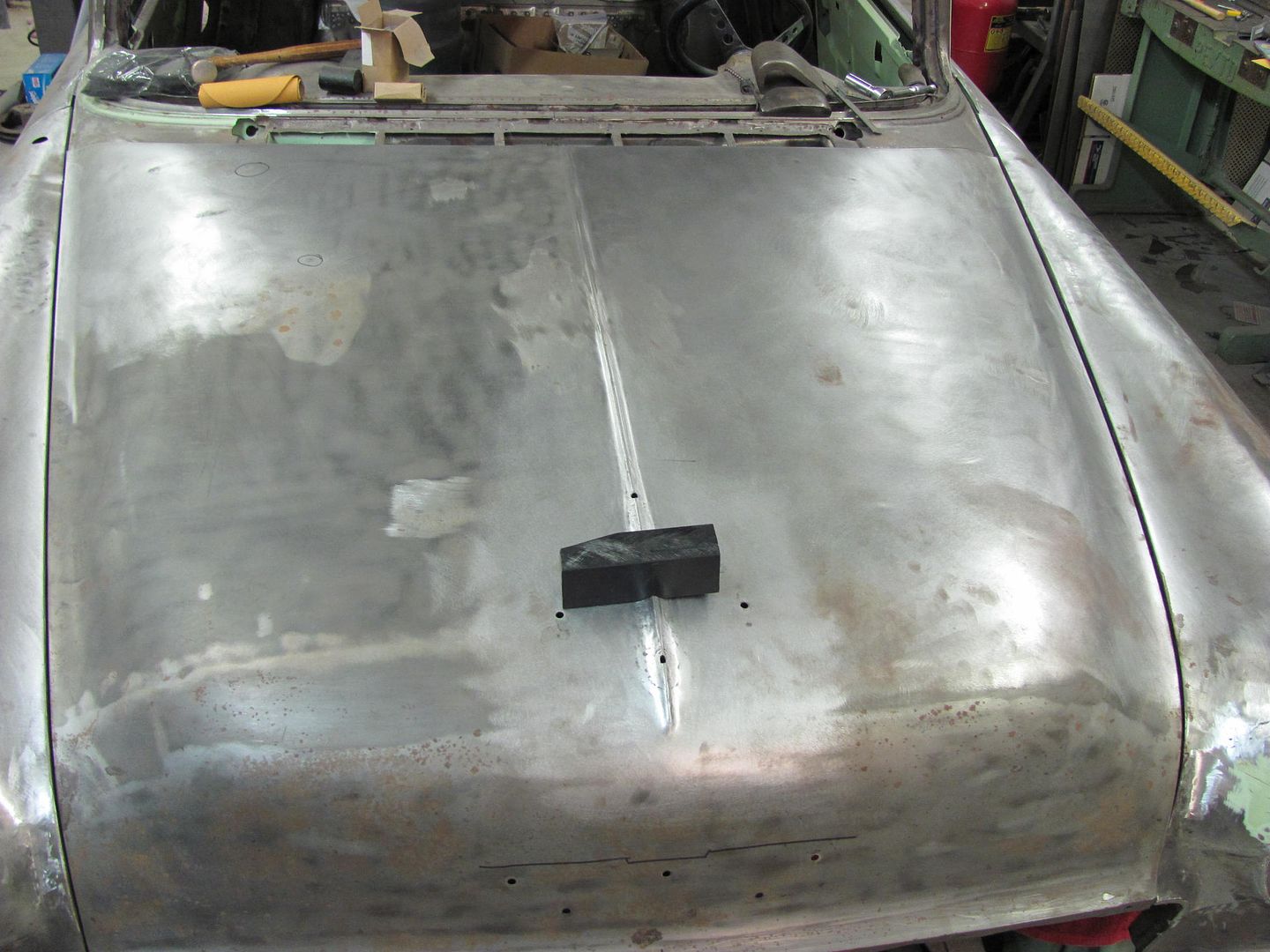
You can see the hood gains more crown toward the front, but the peak also seems to still have more altitude there. It's here where I'll use the shrinking tip on the dent puller to shrink the "valley" a bit more to try for better consistency out to the front.


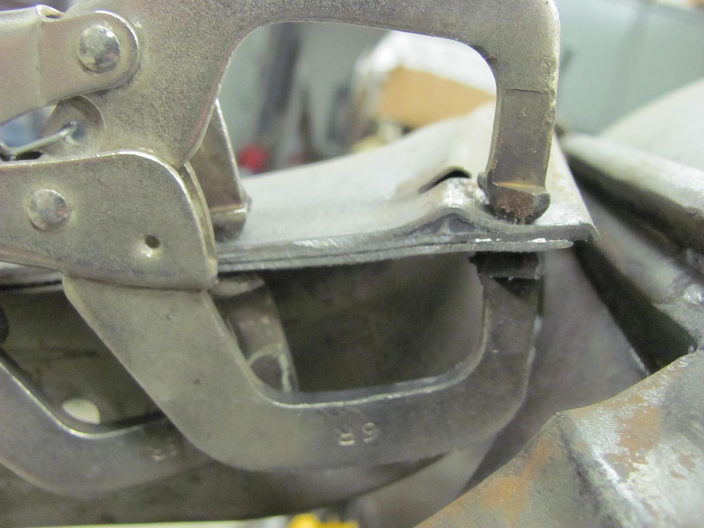
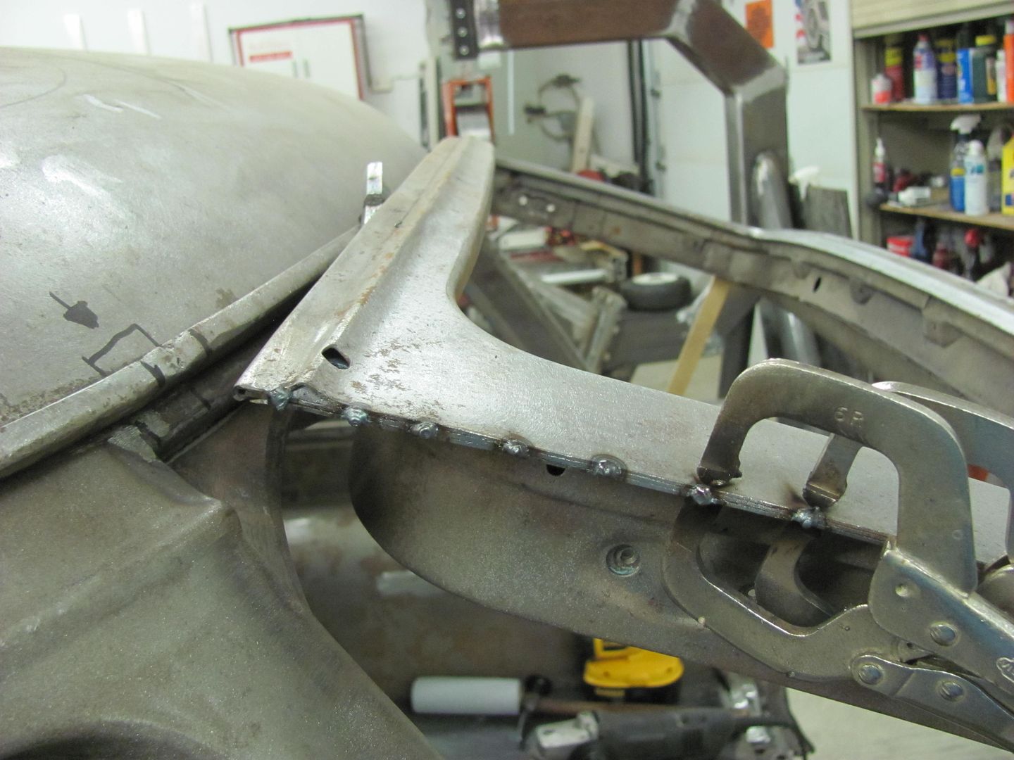
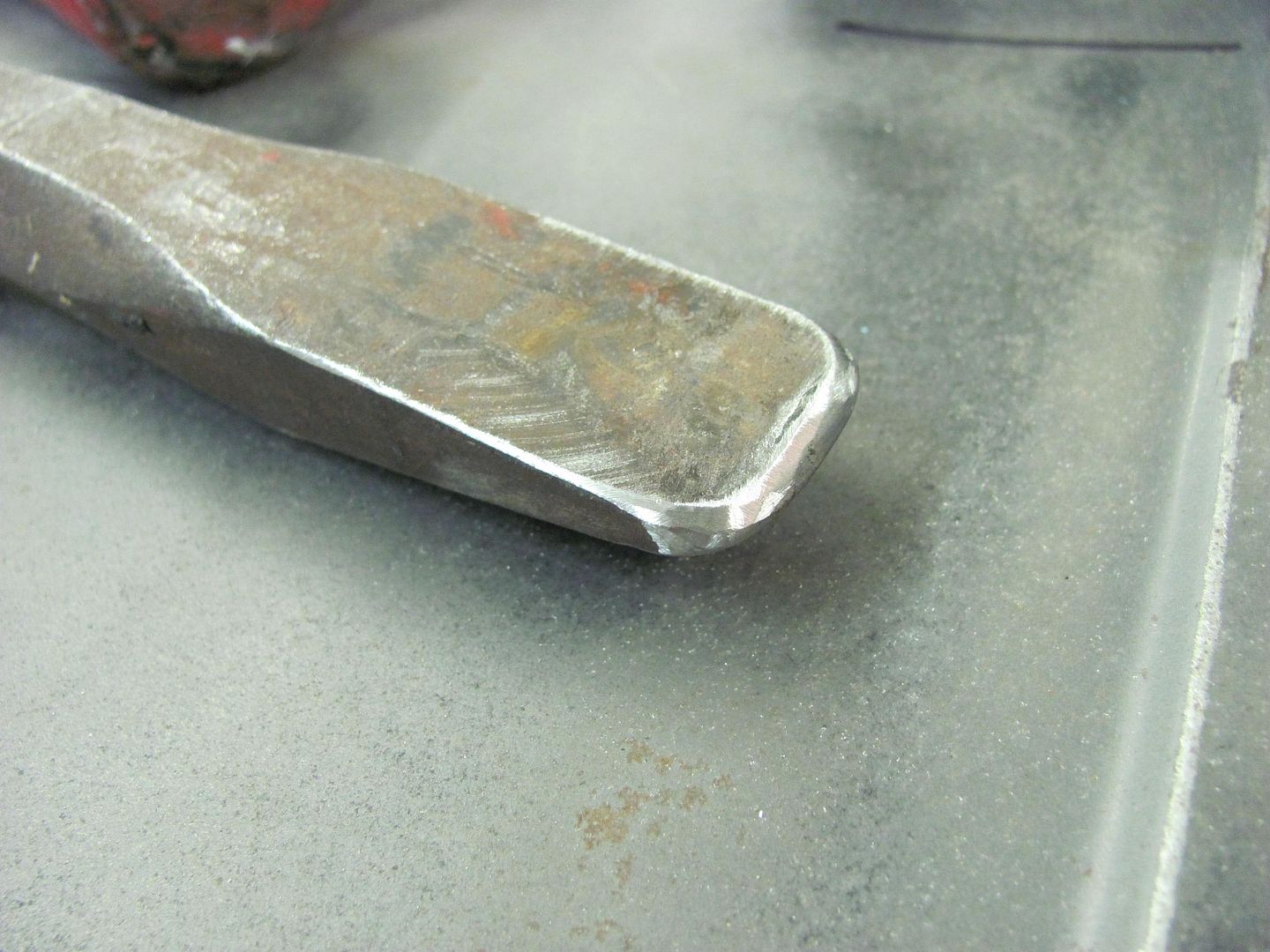
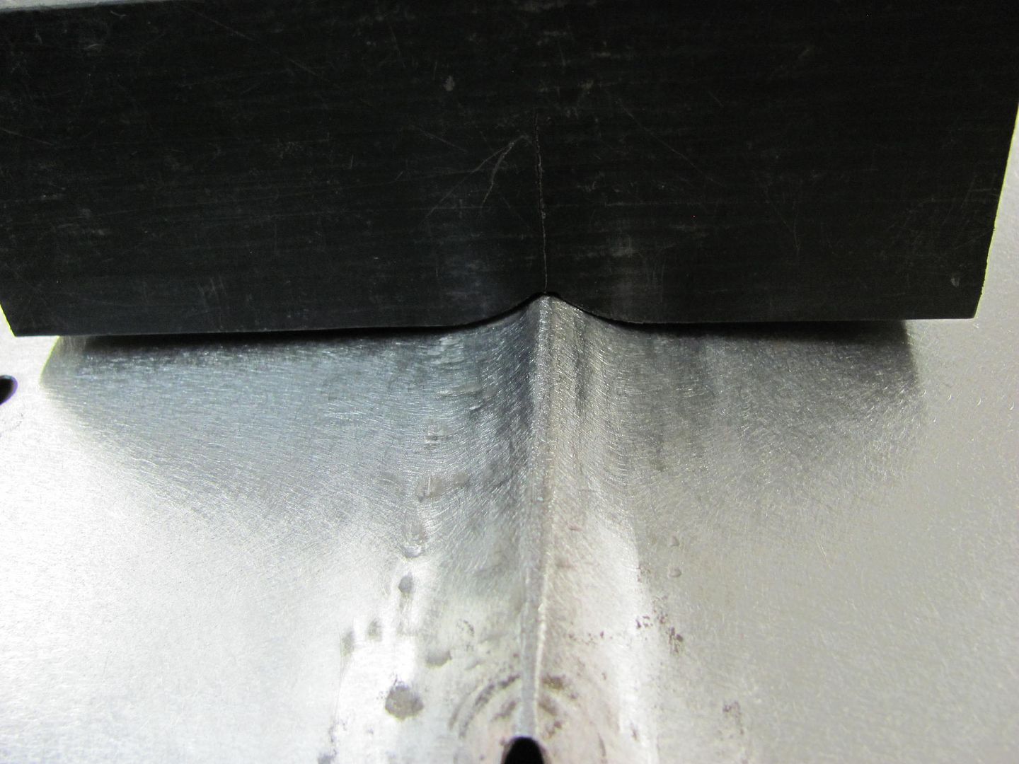
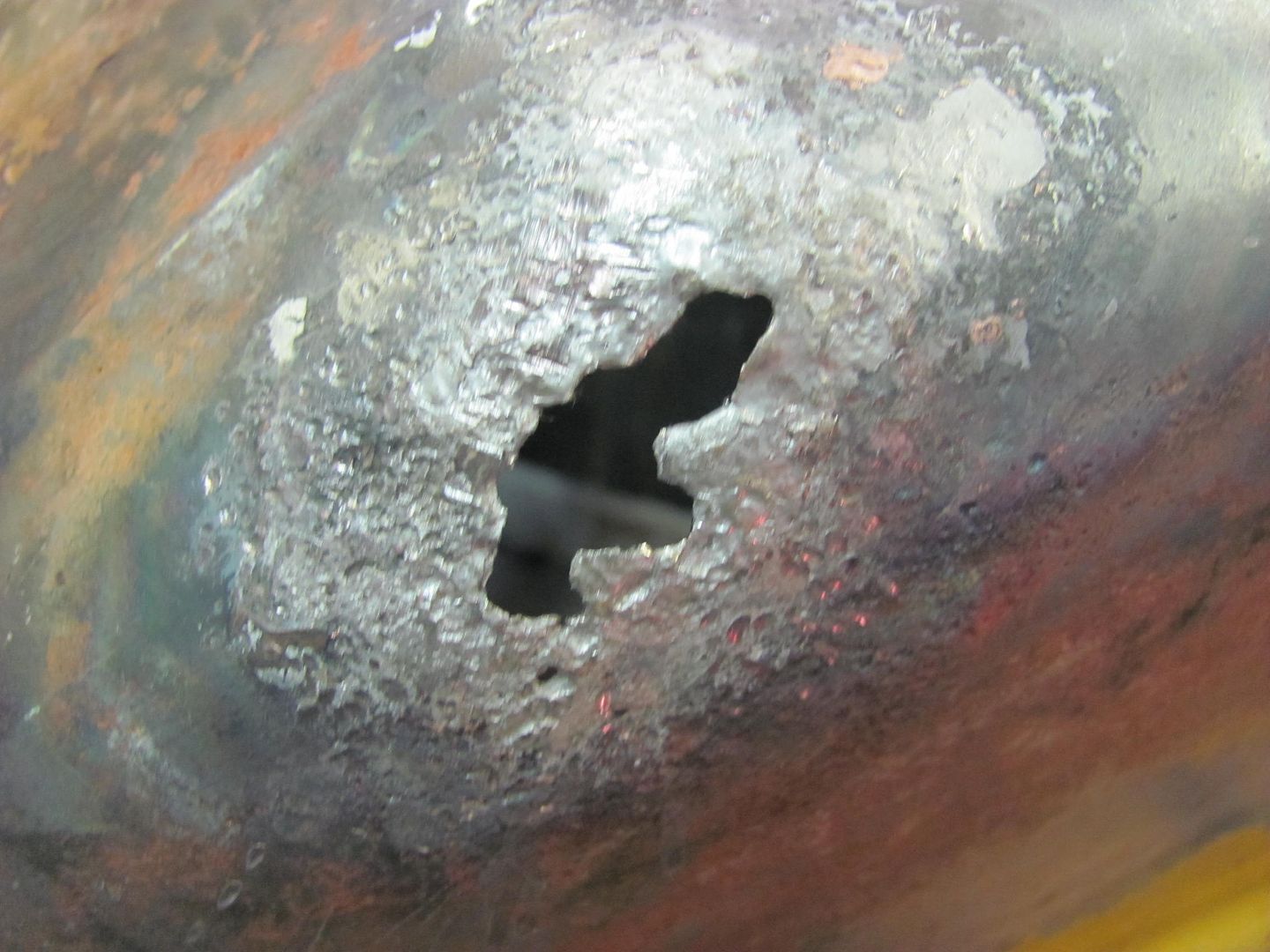
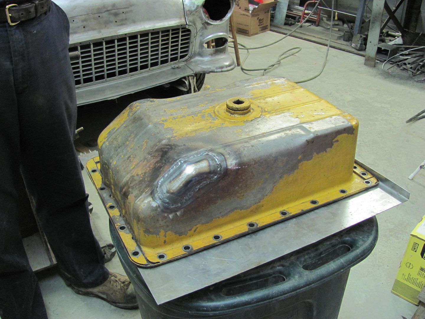
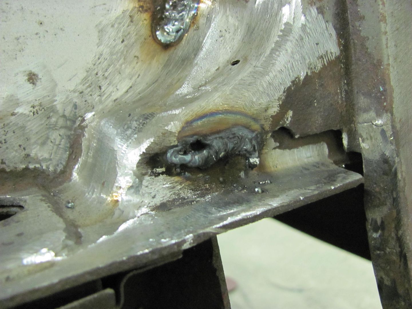
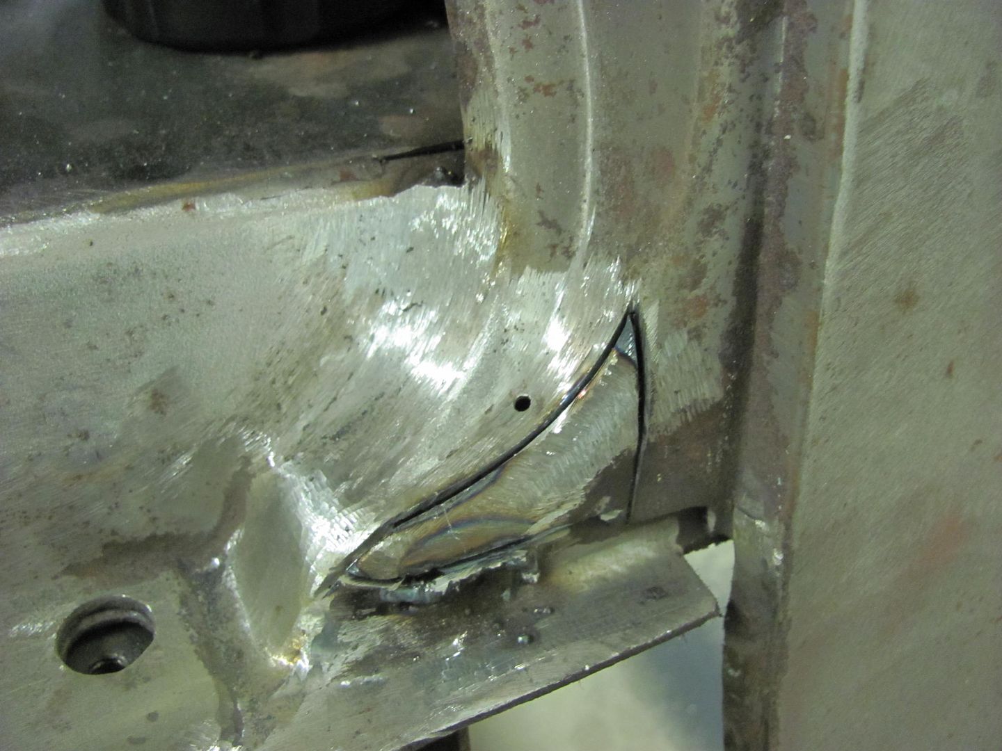
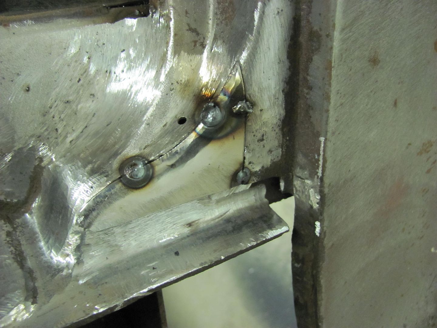
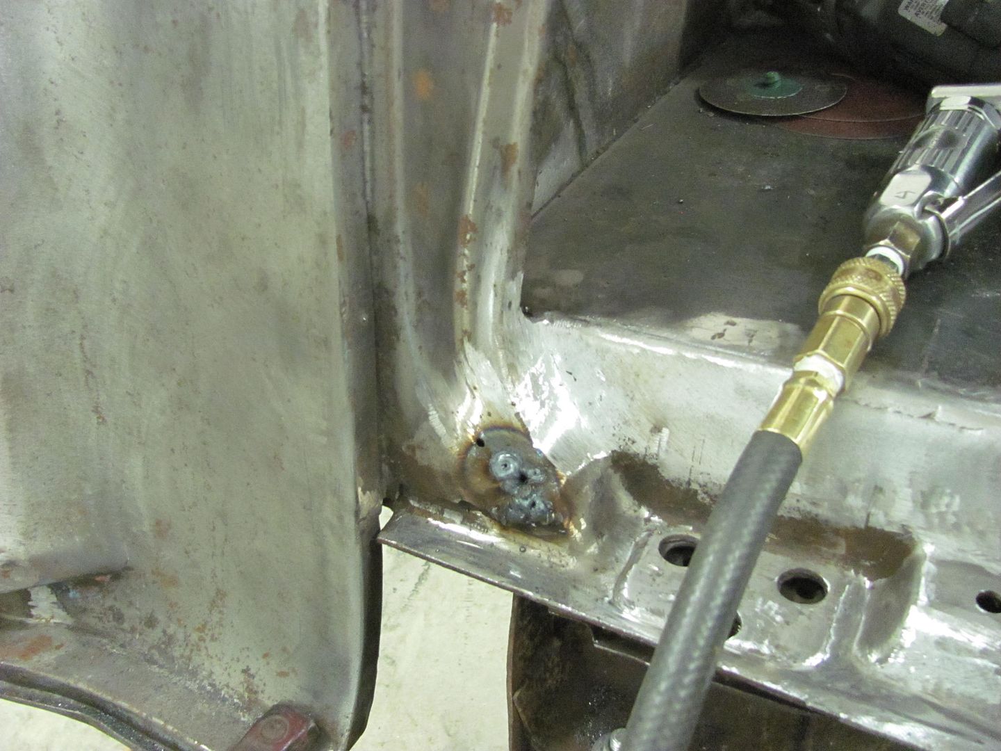
Now to fill in some bird mounting holes... Using my Roper Whitney hand punch to make some plugs for the holes, but the punch part has the locating center point, which will tend to distort the plugs. I found the correct size and ground off the point.


Picture514.jpg


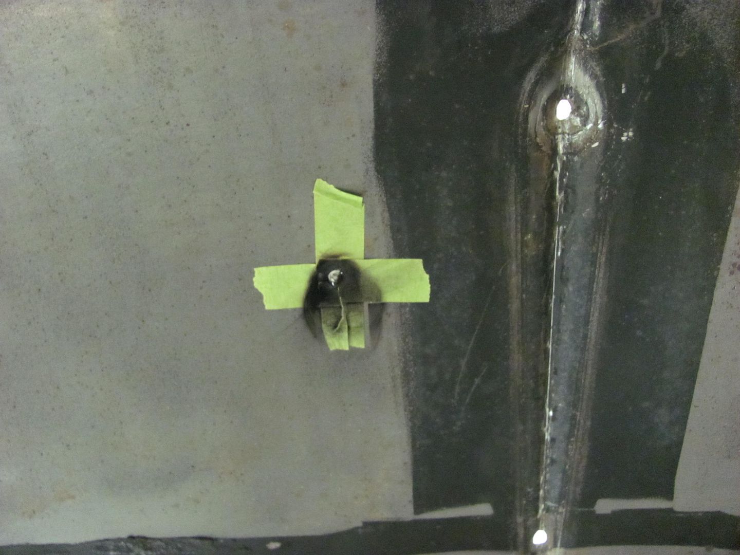
Plug held in place with a couple strips of tape on the bottom, long enough to tack in place....


Picture516.jpg


Picture517.jpg


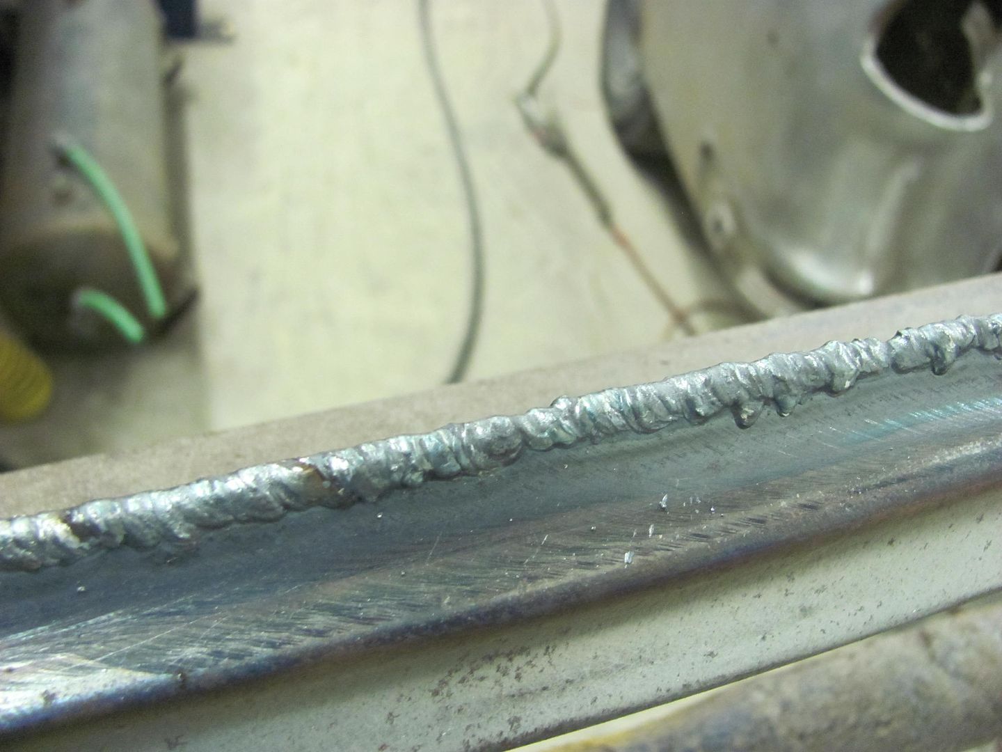
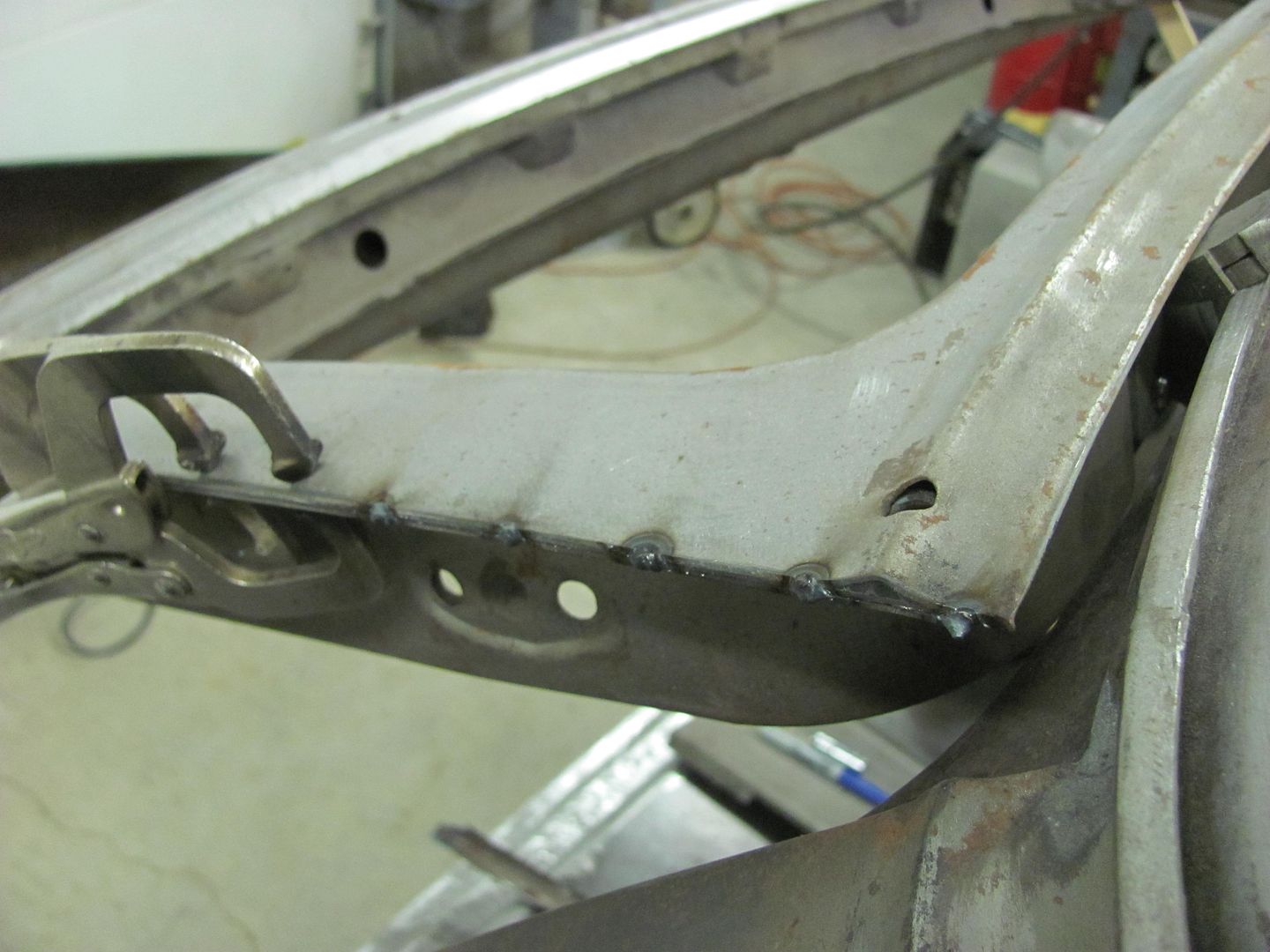
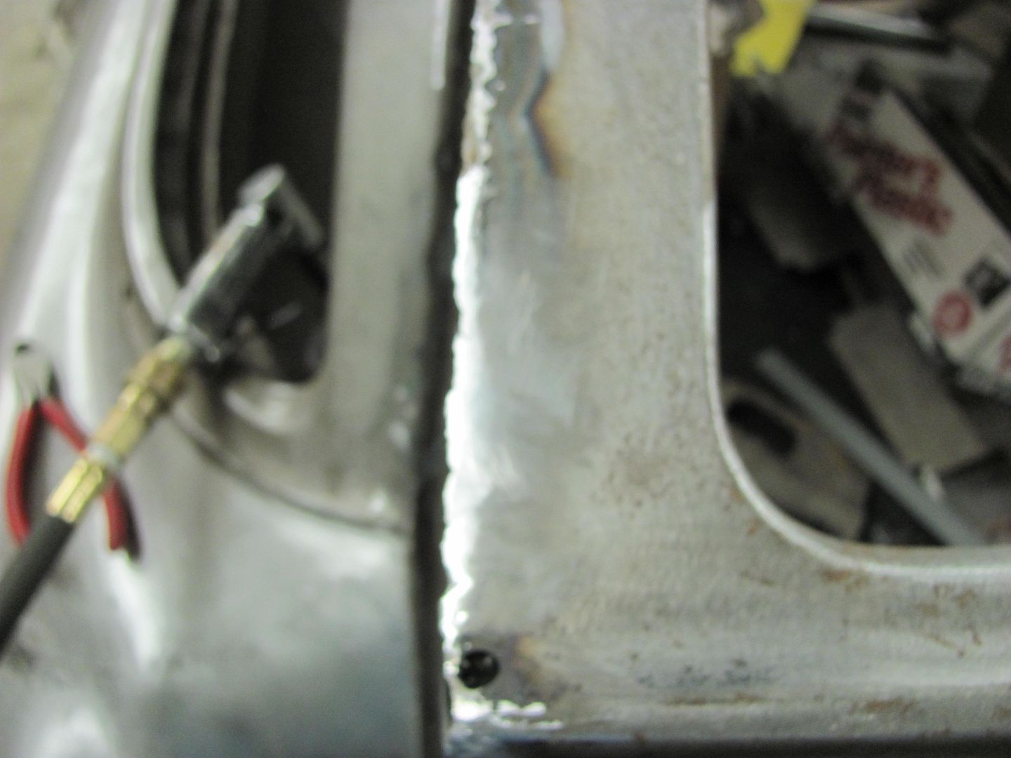
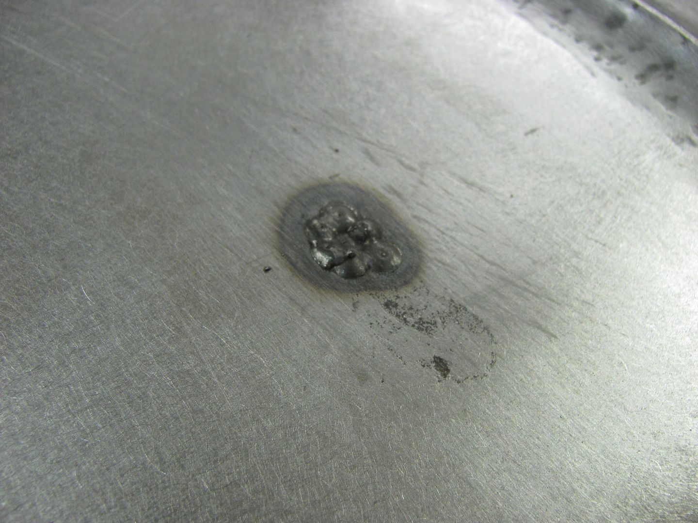
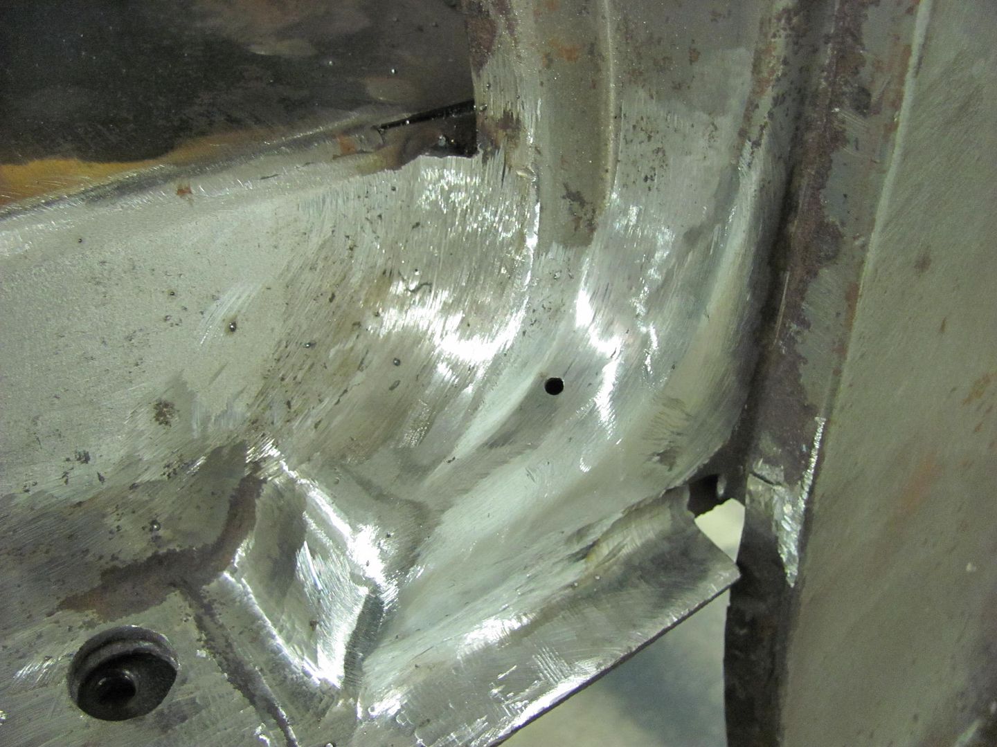
Welded in place and welds dressed....


Picture518.jpg


Picture520.jpg


And here is the video that shows a bit more detail....


.
 
Last edited:

1Garageman

Well-known member
Joined
May 12, 2009
Messages
4,417
Location
Columbus, Ohio
Damn you!! I was just browsing around on this site and I found thread on here. I have been reading this thread and amazed by the photos for the past HOUR! I love your work and can't wait to see more in the future!
Great work!!!!
 

junkman104

Well-known member
Joined
Apr 5, 2005
Messages
4,561
Location
Cherokee County N.C.
Just wanted to put my 2 cents in, great work! I was surprised years ago how bad the body lines on a 55 didn't line up worth a **** until I did one. I spent many hours on the deck lid to the lower panel fit until the owner thought I was being **** with it! Even today I look at the fit when looking at a tri-5.
 

Omphaloskeptic

Well-known member
Joined
Oct 11, 2008
Messages
2,346
Location
Ultima Ratio, Wa.
Robert, thanks for the 'on-line-lesson' in metal work. Did you need to apply any heat to the area to make it easier to move? I was thinking you might have used heat to ease the ornament crown crease. What job did your nephew Chris do for this operation? Was he the Delrin-die-dead-weight-guy? lol

Another question - working on the underside, was the punch and dead-blow hammer the only tools you used, or was there also some body hammer work used there too?
 
OP
M

MP&C

Well-known member
Joined
Oct 21, 2009
Messages
4,396
Location
Leonardtown, MD
Thanks for the comments guys!


Did you need to apply any heat to the area to make it easier to move? I was thinking you might have used heat to ease the ornament crown crease. What job did your nephew Chris do for this operation? Was he the Delrin-die-dead-weight-guy? lol

Another question - working on the underside, was the punch and dead-blow hammer the only tools you used, or was there also some body hammer work used there too?

No heat used. Chris was the delrin guy, but part of that was to also insure the centerline mark on the delrin remained aligned with the centerline mark on the top of the hood. All the while I was crouched in the engine compartment and had to make sure the punch stayed aligned with the centerline mark on the underside.. Basically, it was a gradual progression of working the center crease, then knocking down the plateau edge a bit, then repeating.. until it got to what you see. The good part about it is that as completed the underside will be just as nice as the outside, so for all intents and purposes will appear as factory, subtle..

I meant to get a better shot of the underside when I filmed, I'll have to get the camera back out so you can see that...
 

e-tek

Well-known member
Joined
Dec 19, 2007
Messages
10,690
Location
Saskatoon, SK
Once again proving that the term "Precision Hammering" is NOT an oxymoron!

(Hey, maybe a good name for a bodyshop!)
 
OP
M

MP&C

Well-known member
Joined
Oct 21, 2009
Messages
4,396
Location
Leonardtown, MD
So today I got a phone call, and long story short, needed to do some metalshaping for a Caterpillar D5 dozer. No, really! The last time this same mishap occurred was over ten years ago in my back yard. It seems dirt/mud gets packed between the stump pan and the oil pan, until a hole rusts through the oil pan. Last time Paul bought a new oil pan, but it sounded like he needed to use the dozer this week, so he brought it over for repair..


Picture232.jpg


Picture234.jpg


Picture235.jpg


The heat marking is where he was attempting to braze it closed, with little success. Calipers showed the pan to be 14 ga, and I just happened to have some in stock. I've used the bead roller before to form a radius, but never on metal this thick before. This will be a good test of the fancy 75A durometer skateboard wheel to see how well it works.


Picture236.jpg


Picture238.jpg


Picture239.jpg


Took a few passes, but worked real nice. Now for a relief cut and a weld...


Picture240.jpg


Picture241.jpg


Picture242.jpg


Picture243.jpg


Picture246.jpg


Picture247.jpg


Picture248.jpg


Rust hole removed, patch trimmed and fitted, then welded in place..


Picture252.jpg


Picture253.jpg


Picture255.jpg


.....and Paul cleans it up for paint..


Picture257.jpg


You never know what you see over here in the shop... :lol_hitti
 
Last edited:

larry4406

Well-known member
Joined
Jan 27, 2006
Messages
18,972
Location
Northern Virginia
Excellent! How do you achieve such tight gaps for fitting the patch? Cut the hole first then successively trim and fit the patch to the hole? What are you using to cut the hole?
 
OP
M

MP&C

Well-known member
Joined
Oct 21, 2009
Messages
4,396
Location
Leonardtown, MD
Hi Larry! The patch was formed, cut out on the band saw, fine tuned with a sanding disc and radiuses added, then placed over the rust area and the outline scribed. I used a 3" x .035 cutoff wheel to slice through the oil pan and rough cut the hole, cutting out the corners diagonally within the scribe mark. Then the blue die grinder in the picture was used, it has a 1-1/2" drum sander on it, and got all the corners rounded out. The final fitment trimming was done on the patch.
 

BJ42LX

Well-known member
Joined
Dec 29, 2010
Messages
2,811
Location
WNY
I'm impressed the hole got this big before it needed repair. The mud and rust must have been packing the hole for months/years!


Picture235.jpg
 
OP
M

MP&C

Well-known member
Joined
Oct 21, 2009
Messages
4,396
Location
Leonardtown, MD
I'm not sure that some of the hole size can't be attributed to his attempts at repair, but that is how it showed up here...
 
OP
M

MP&C

Well-known member
Joined
Oct 21, 2009
Messages
4,396
Location
Leonardtown, MD
Thanks!

Spent tonight working on the tailgate jamb area, touching up some factory welds in preparation of installing the rear tail pan. Wasn't too long before Murphy's law reared its ugly head, and the lower part of the jamb showed some signs of rust lurking inside.


Picture229.jpg


Cut open an access hole and cleaned out the inside as best I could for welding in some new metal..


Picture230.jpg


Picture231.jpg


For making a replacement, I have an "anvil" I made recently out of some scraps from under the welding table...


Picture232.jpg


Picture233.jpg


Picture234.jpg


Here's the anvil end we'll use this evening as matched up to the original...


Picture236.jpg


Picture237.jpg


Picture240.jpg


Fitting, trimming, and welding...


Picture242.jpg


Picture243.jpg


Picture246.jpg


Picture247.jpg


Picture248.jpg


Picture249.jpg


....and, as can be expected, one more to go... Until next time.


Picture250.jpg
 
OP
M

MP&C

Well-known member
Joined
Oct 21, 2009
Messages
4,396
Location
Leonardtown, MD
I did get some more accomplished on the shop truck this evening. The bracket for the passenger side was drilled for the compressed bolt pattern and then the old holes welded in. I learned from the last time, welds are tougher to drill, so weld afterward. Looks like I forgot pics of the final welded up version.....


Picture006-1.jpg


Picture007-1.jpg


Then, back to the crossmember that bolts between these brackets, the original frame rails on the donor school bus was 11" high, where the factory rails are about 6.. This requires a slight mod to the crossmember, and explains the compressed bolt pattern..


Picture229.jpg


Picture230.jpg


Modifying the final end...here's the cut line....


Picture232.jpg


Picture008-1.jpg


Picture009-1.jpg


Welded in........


Picture011-1.jpg


Picture013-1.jpg


All ready for install.


Picture014-1.jpg


Next on the list will be to measure out the location for drilling the passenger frame rail..
 
To avoid these ads, REGISTER NOW!
Top Bottom