michjacket
Well-known member
Your craftsmanship is impressive! Can you please give us an idea how long it takes you to accomplish one of these projects? I know I would take days and it would not come out nearly as nice as yours! Thanks for sharing.


")
Still trying to source some short slides.. we'll see.
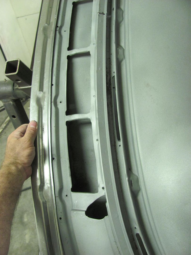
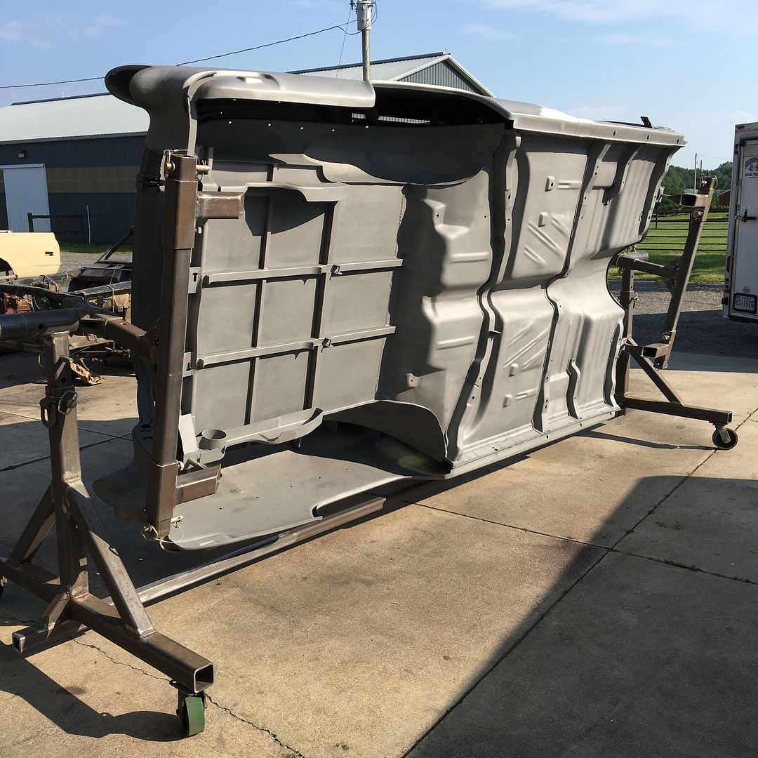
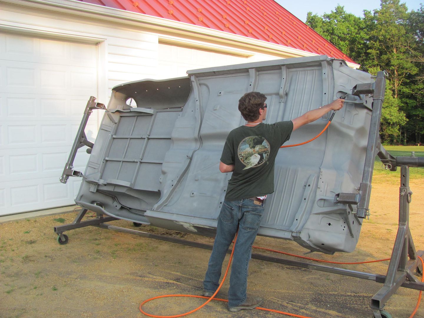
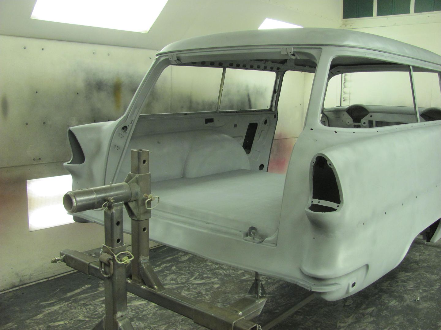
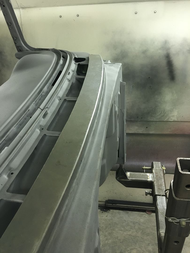
Well the two weeks plus of non stop rain has finally subsided where the media blasting could commence. Got a phone call today that the car was ready to pick up.. Here it is before we loaded it up..
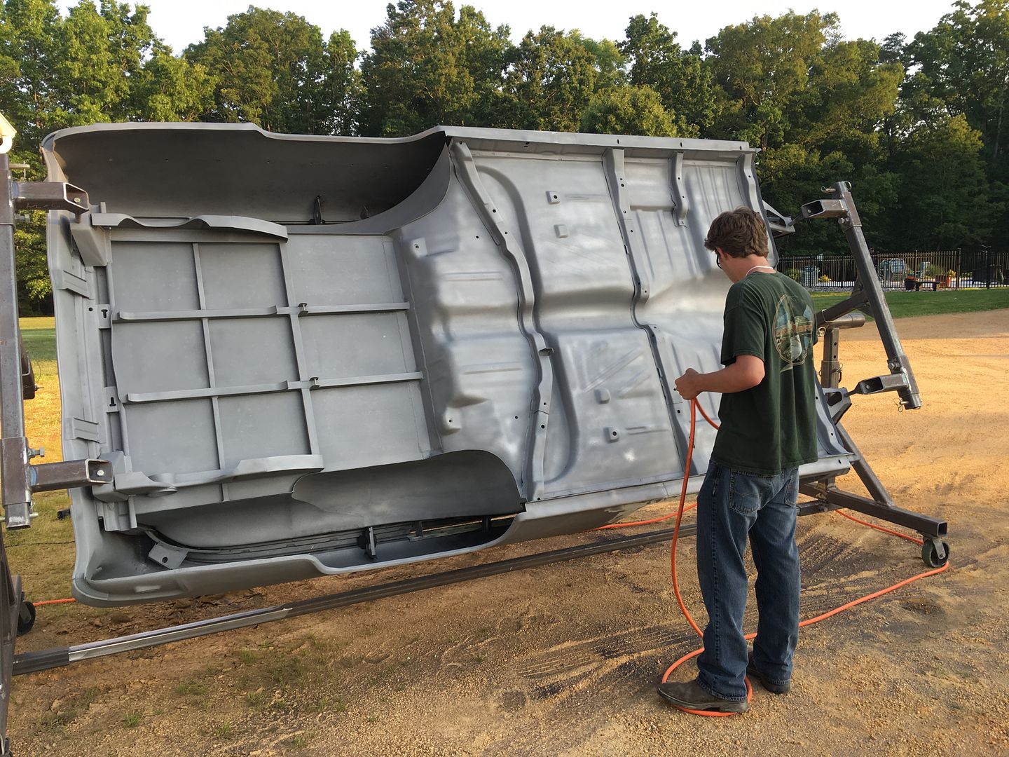
This is the part where you wish you had a tilt bed trailer so any media residue would be persuaded on out on the return trip home... But alas, we found a combination of using the air hose and a shop vac best to evacuate most of the media. That and about 50 or so revolutions on the rotisserie.....
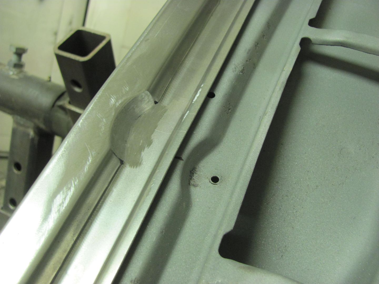
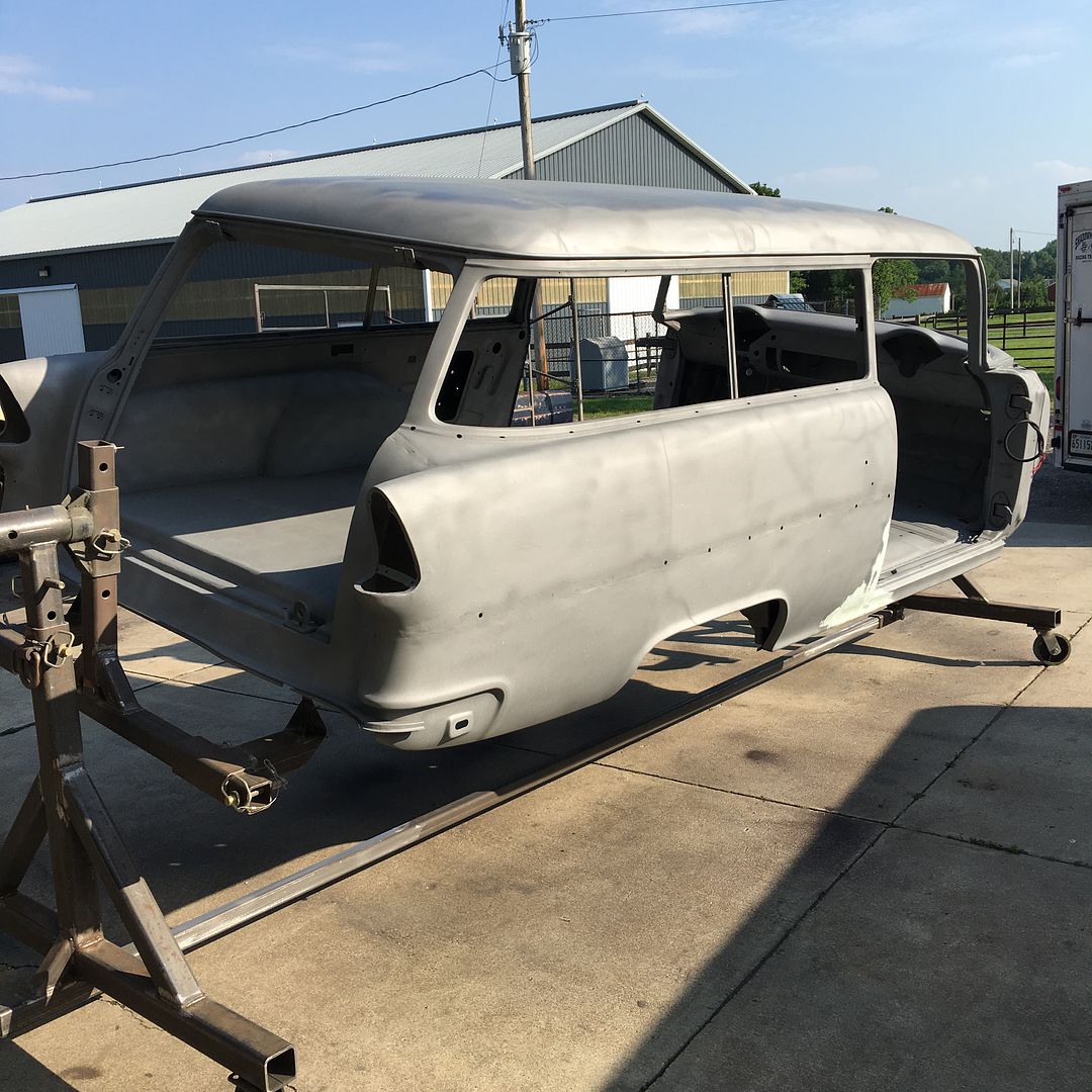
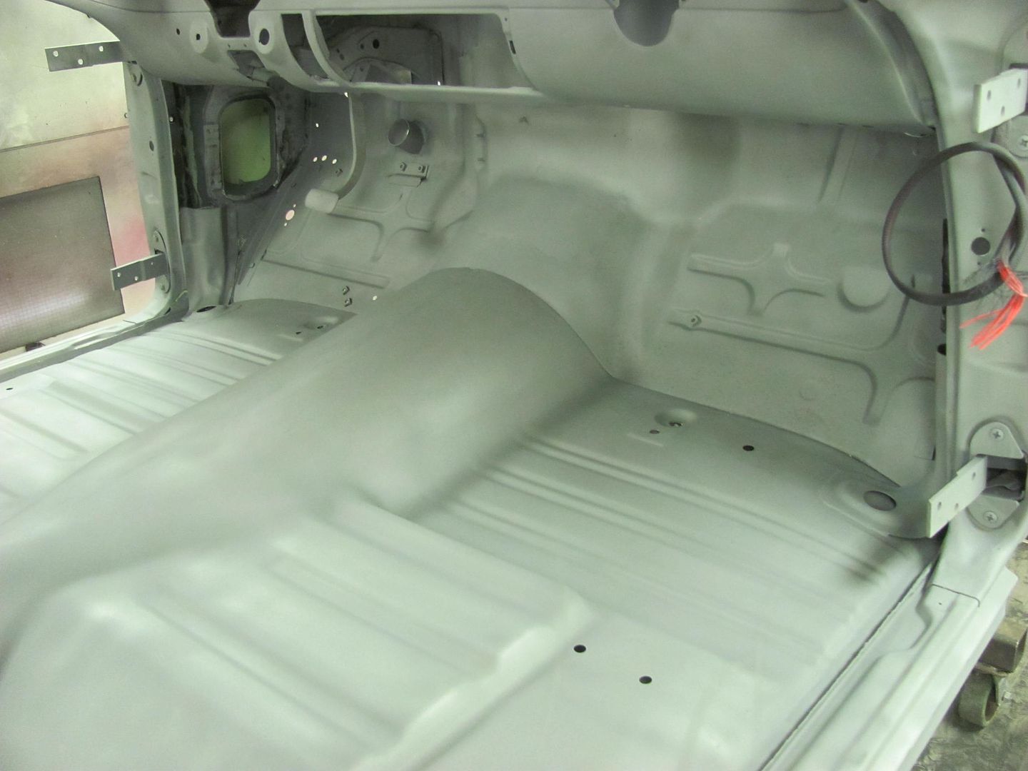
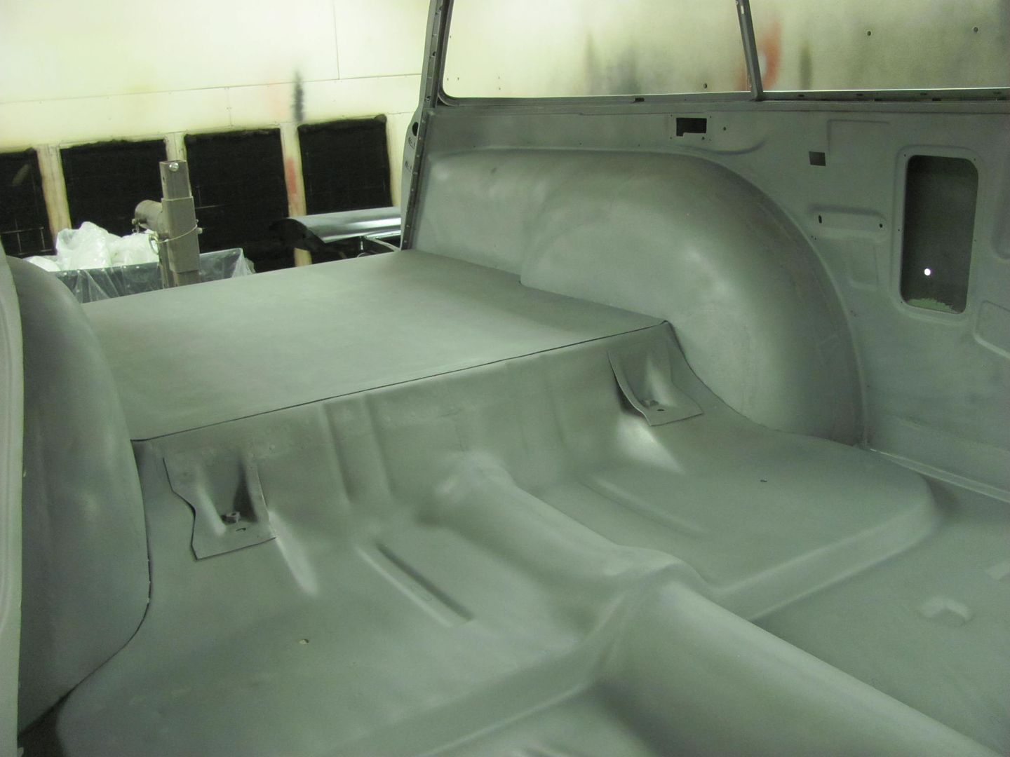
Real pleased with how well it turned out... here moved into the booth and the dehumidifier energized.
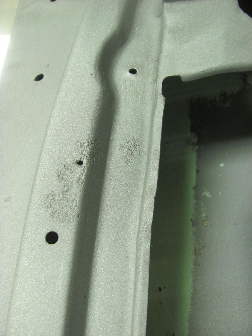
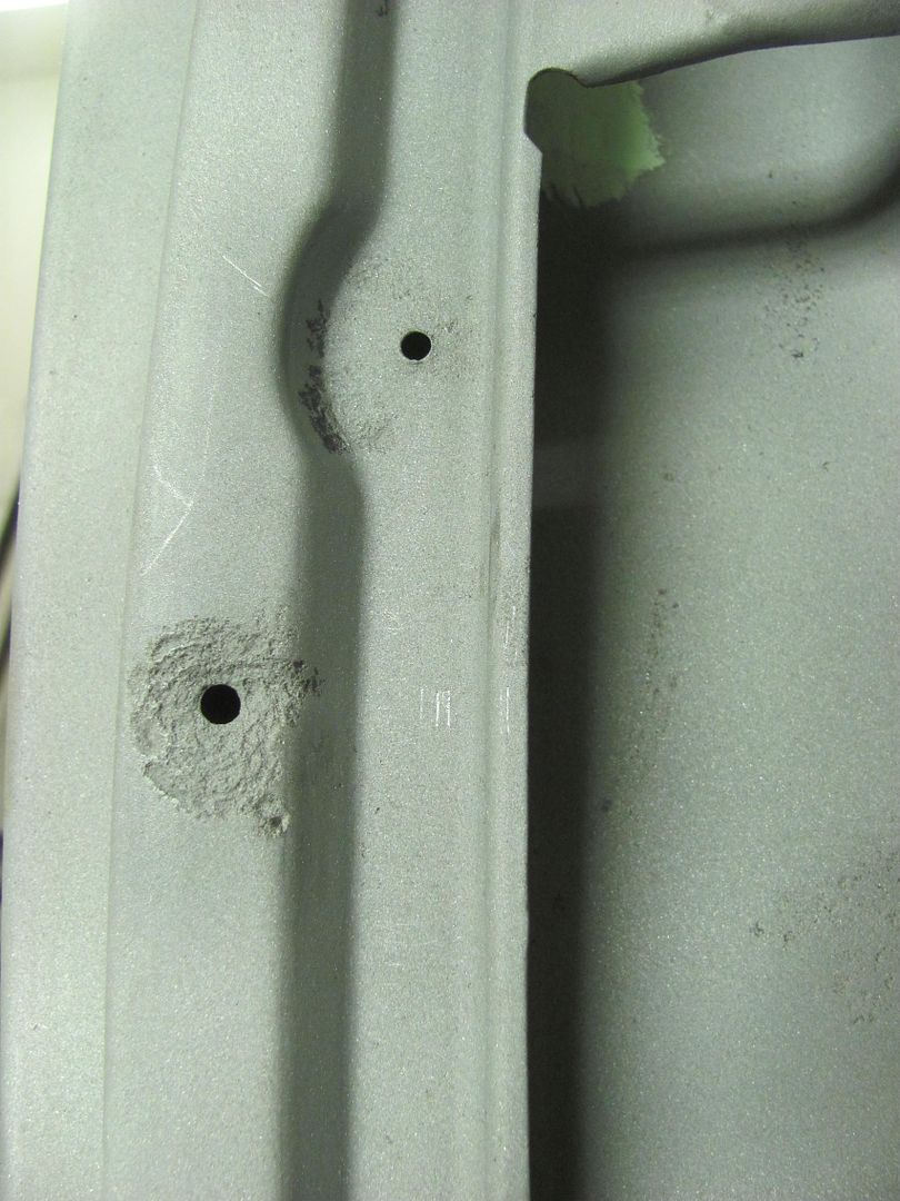
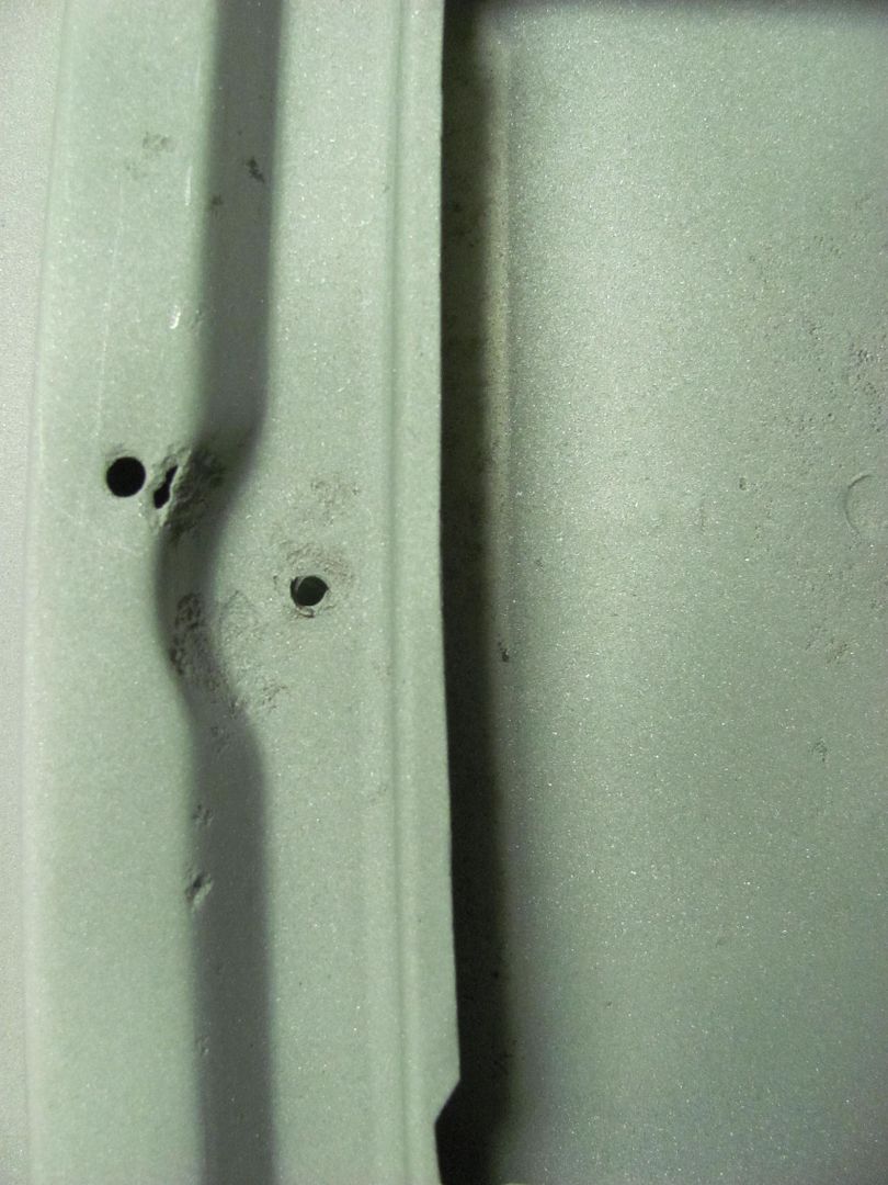
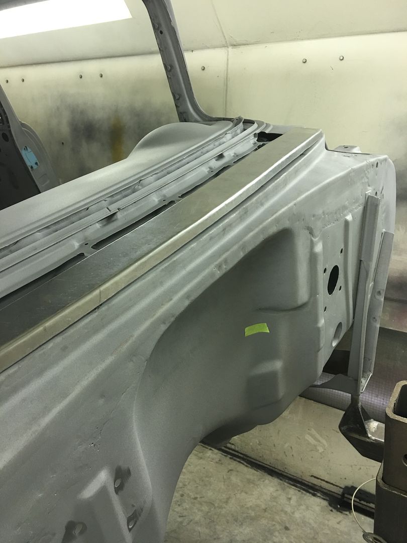
We do have some pin holes that are more apparent now, so we'll get those fixed Saturday morning and see how the weather looks for priming in the afternoon..
Oh, it almost looks like the body was shot with an off green color primer.
Thank you!
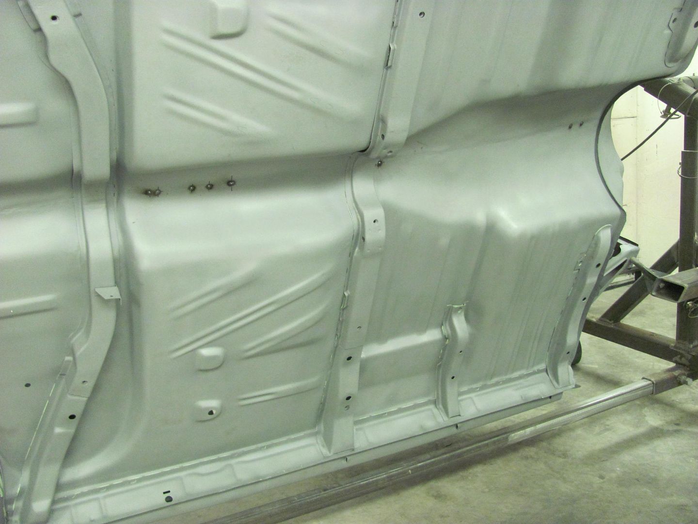
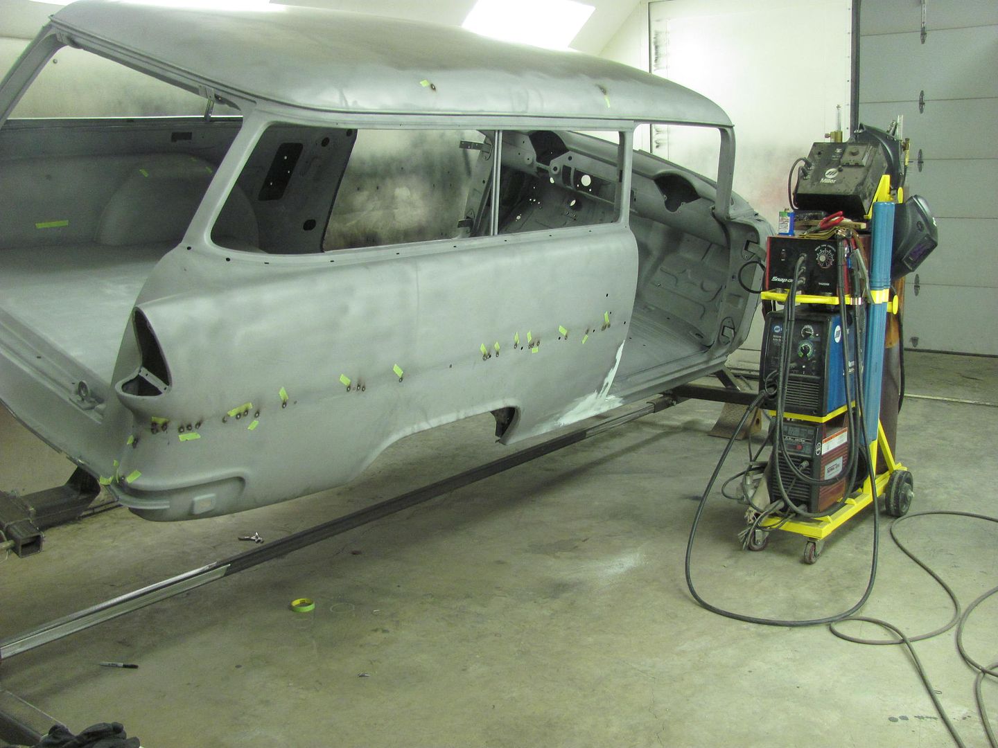
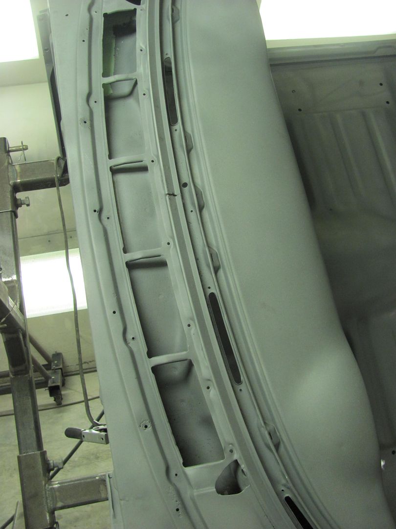
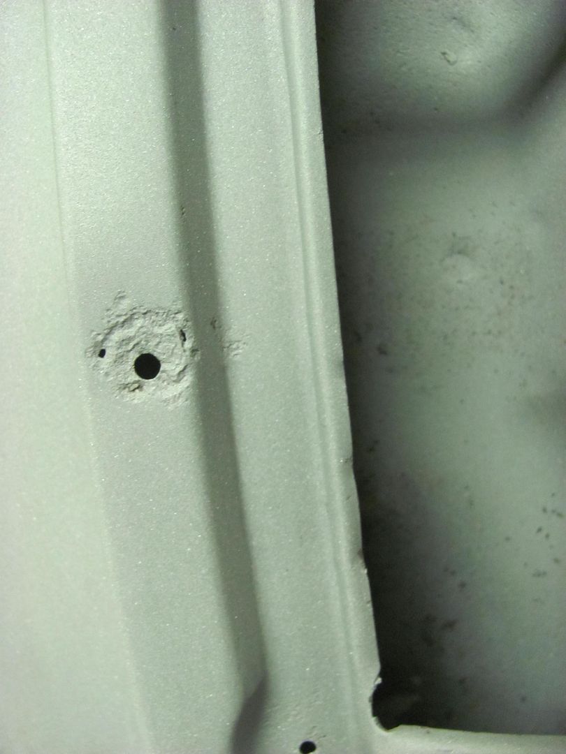
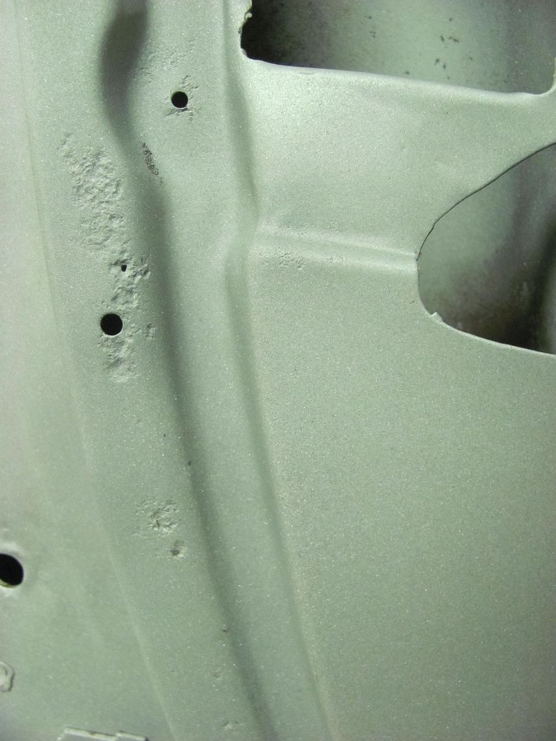
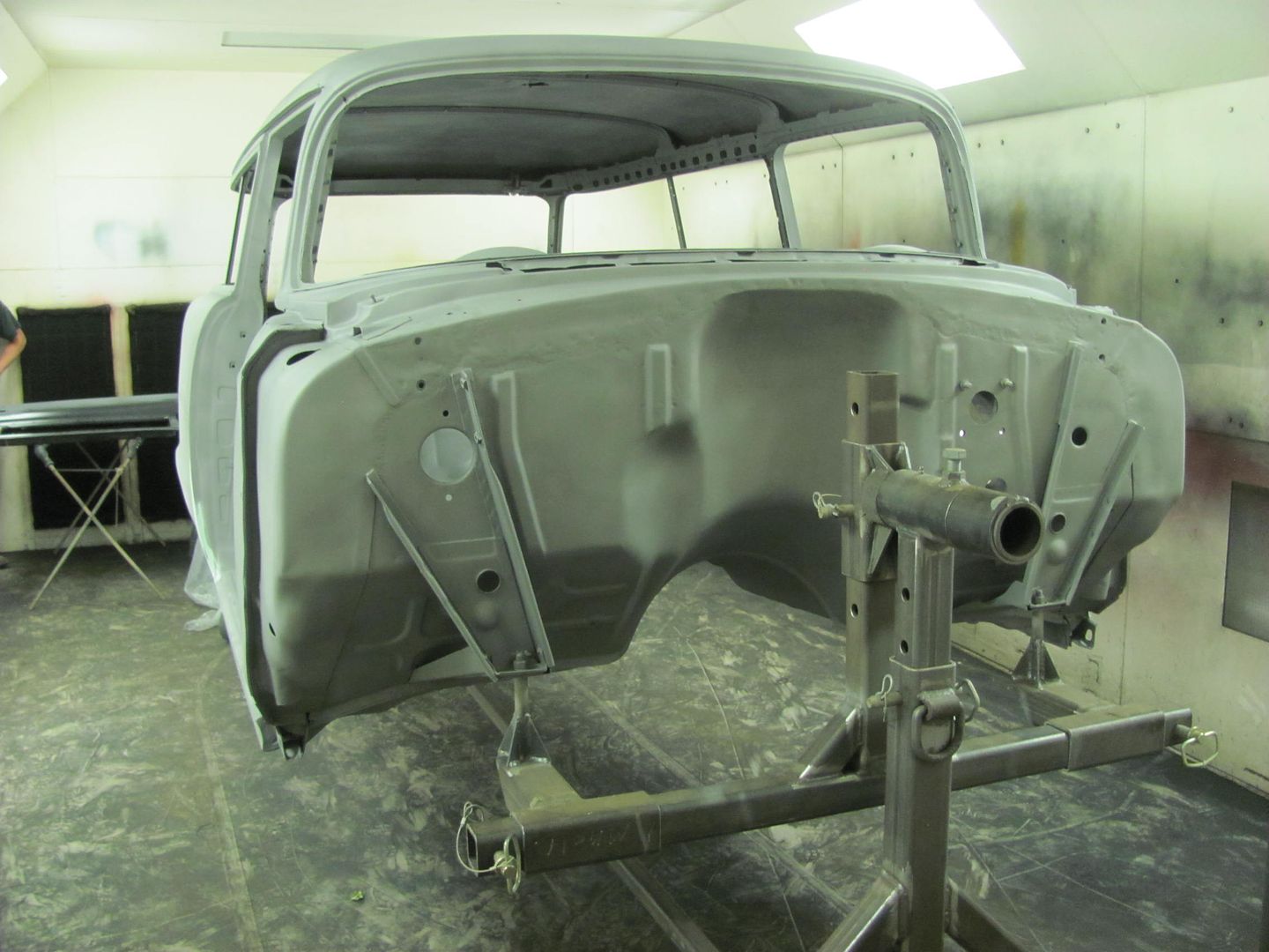
Those last pics were of it in bare metal..
Should be priming soon... once the dominos stop falling.
Why do you make me feel like a .......
Beautiful work!
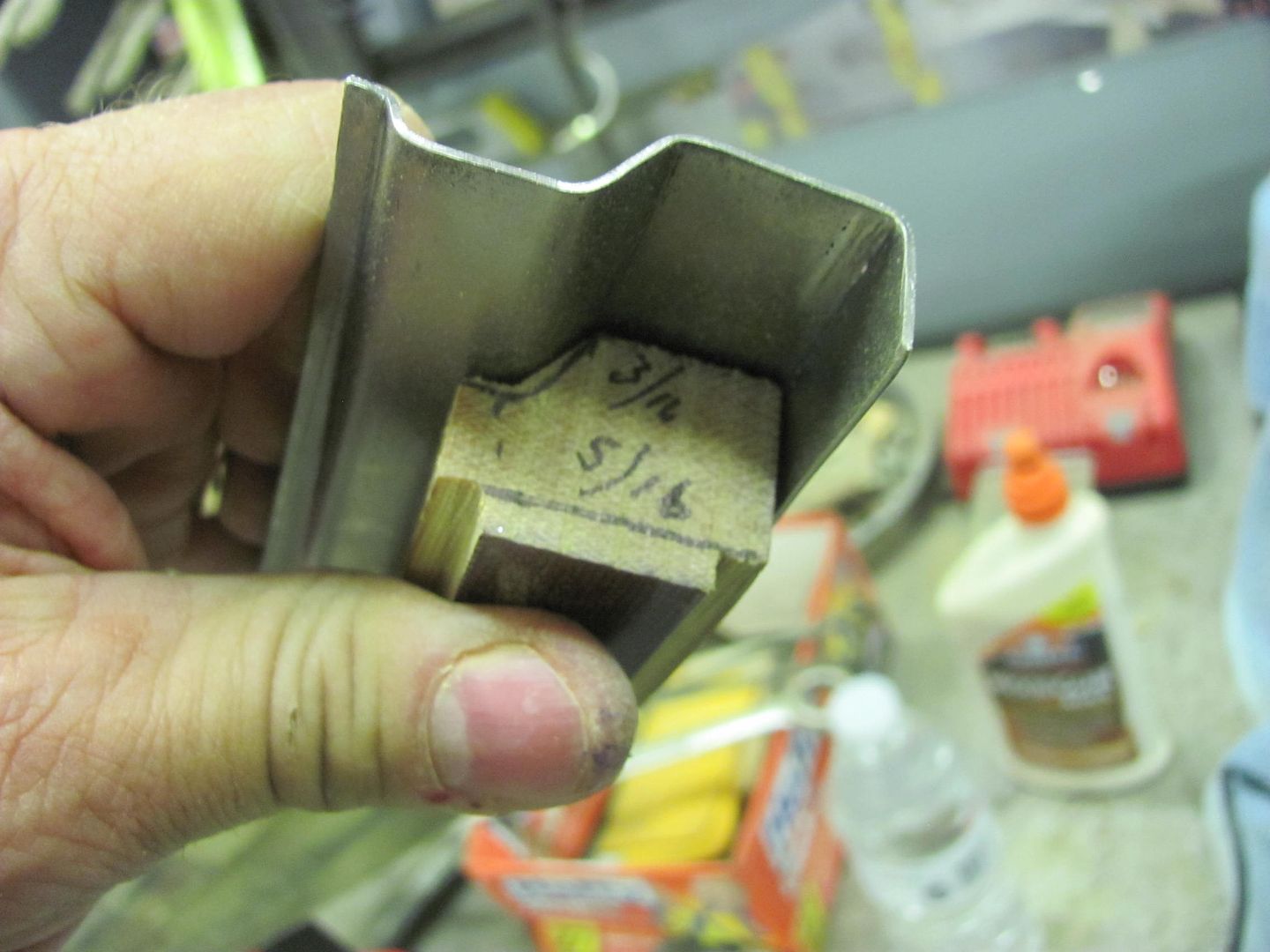
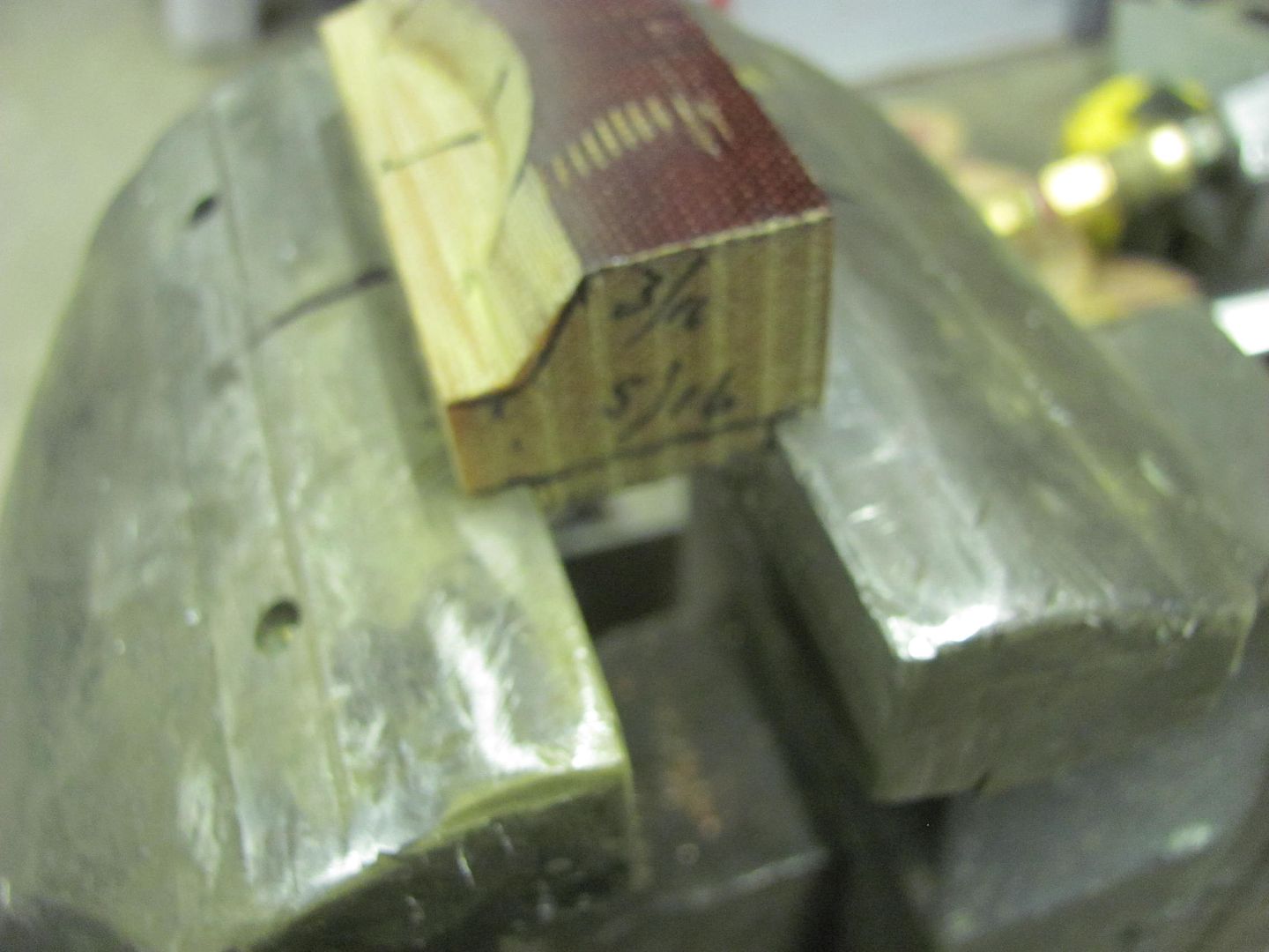
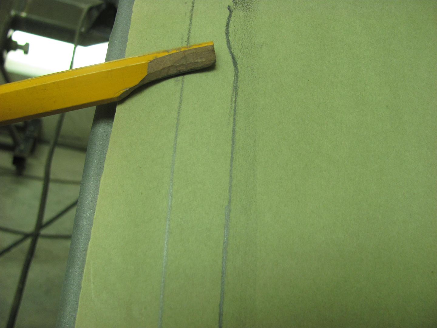
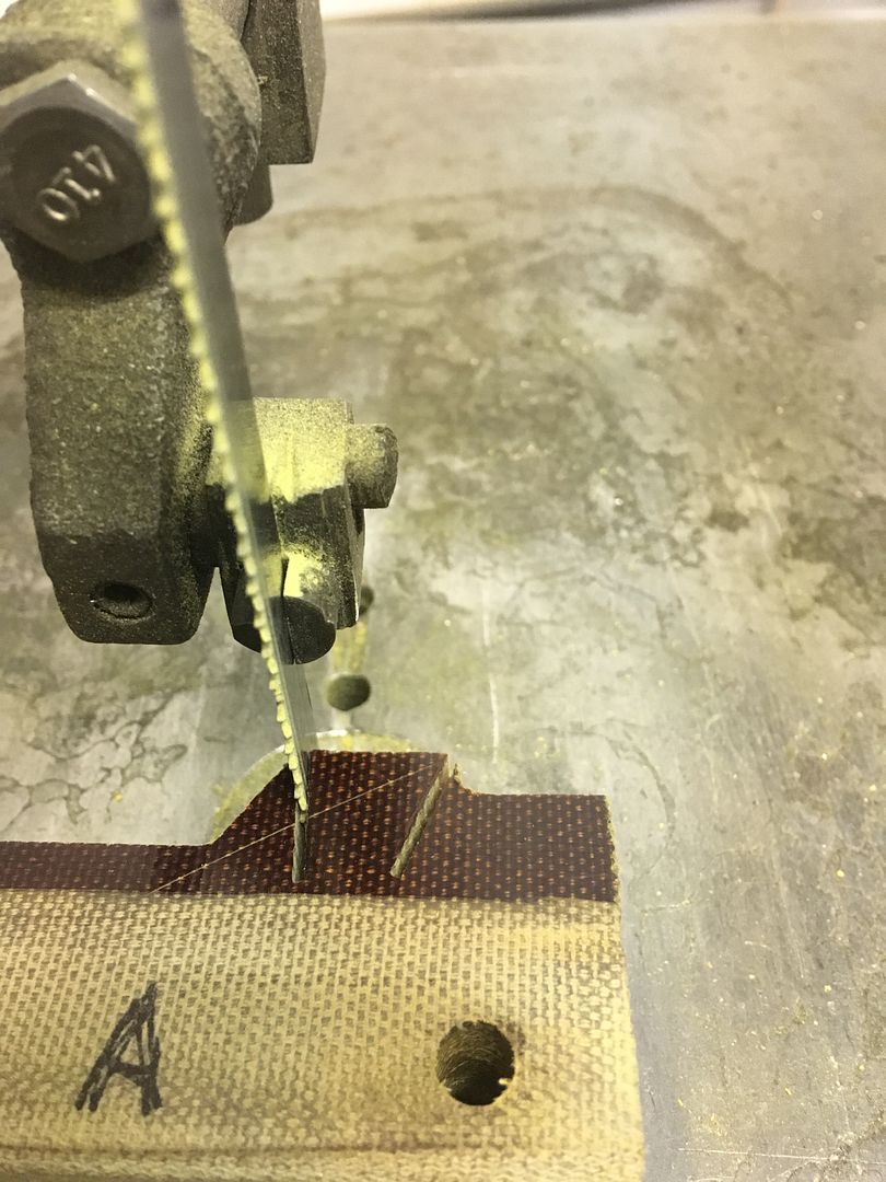
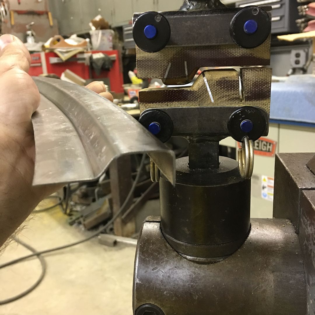
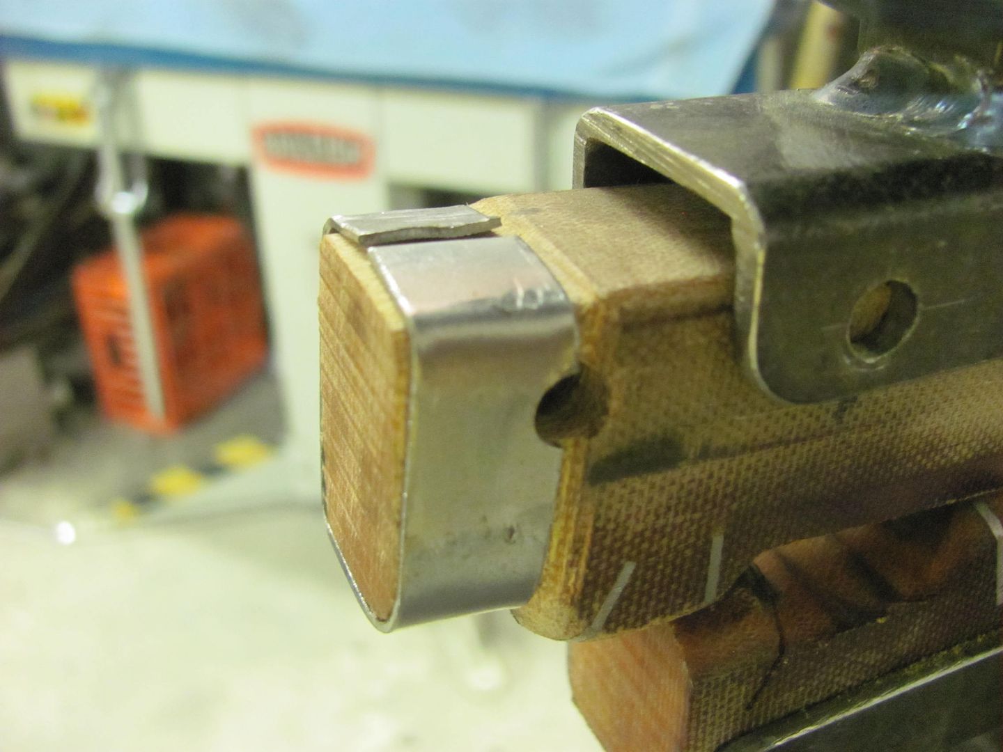
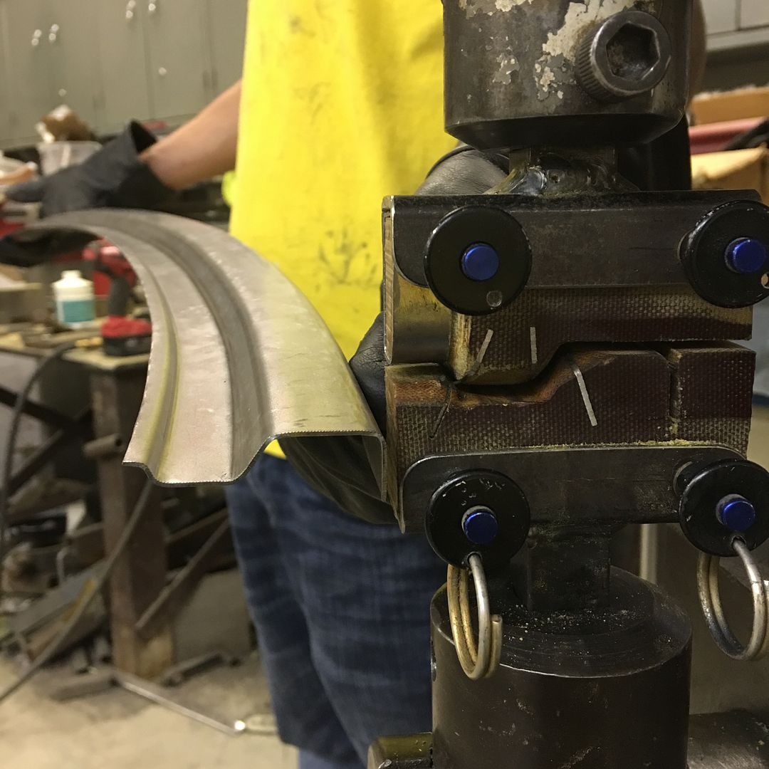
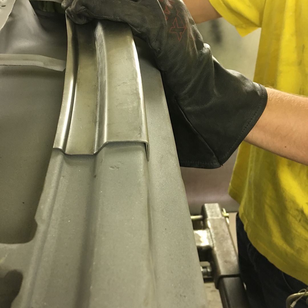
The phenolic is easier (quicker) to cut and sand in details over using steel. If you haven't priced it though, you might not care for it due to price. Now if you see some on the used/salvage market, pick it up quick! As you point out, this works well for a one-off or short production run, but someone making a grunch of something would want steel for the longevity.
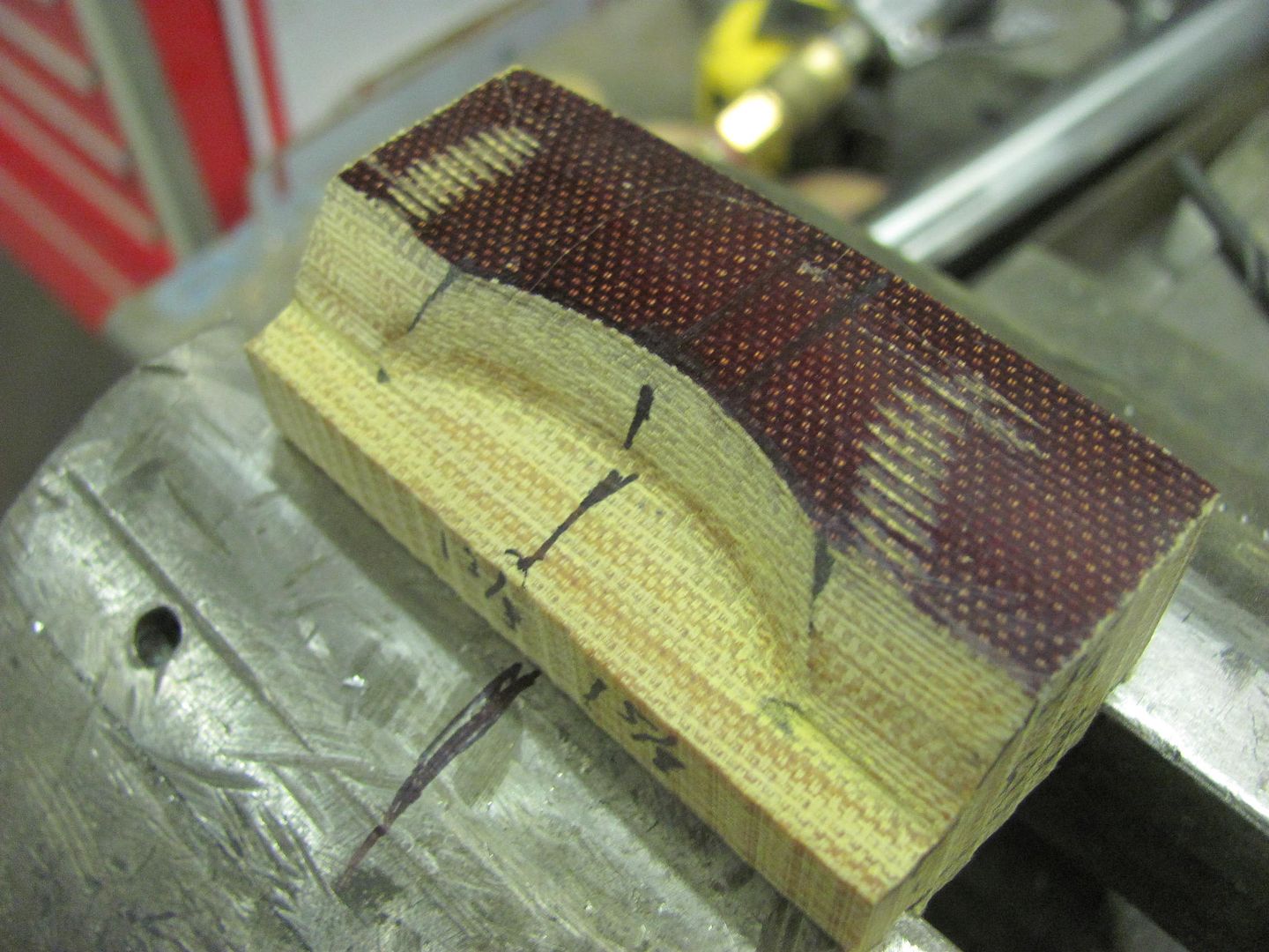
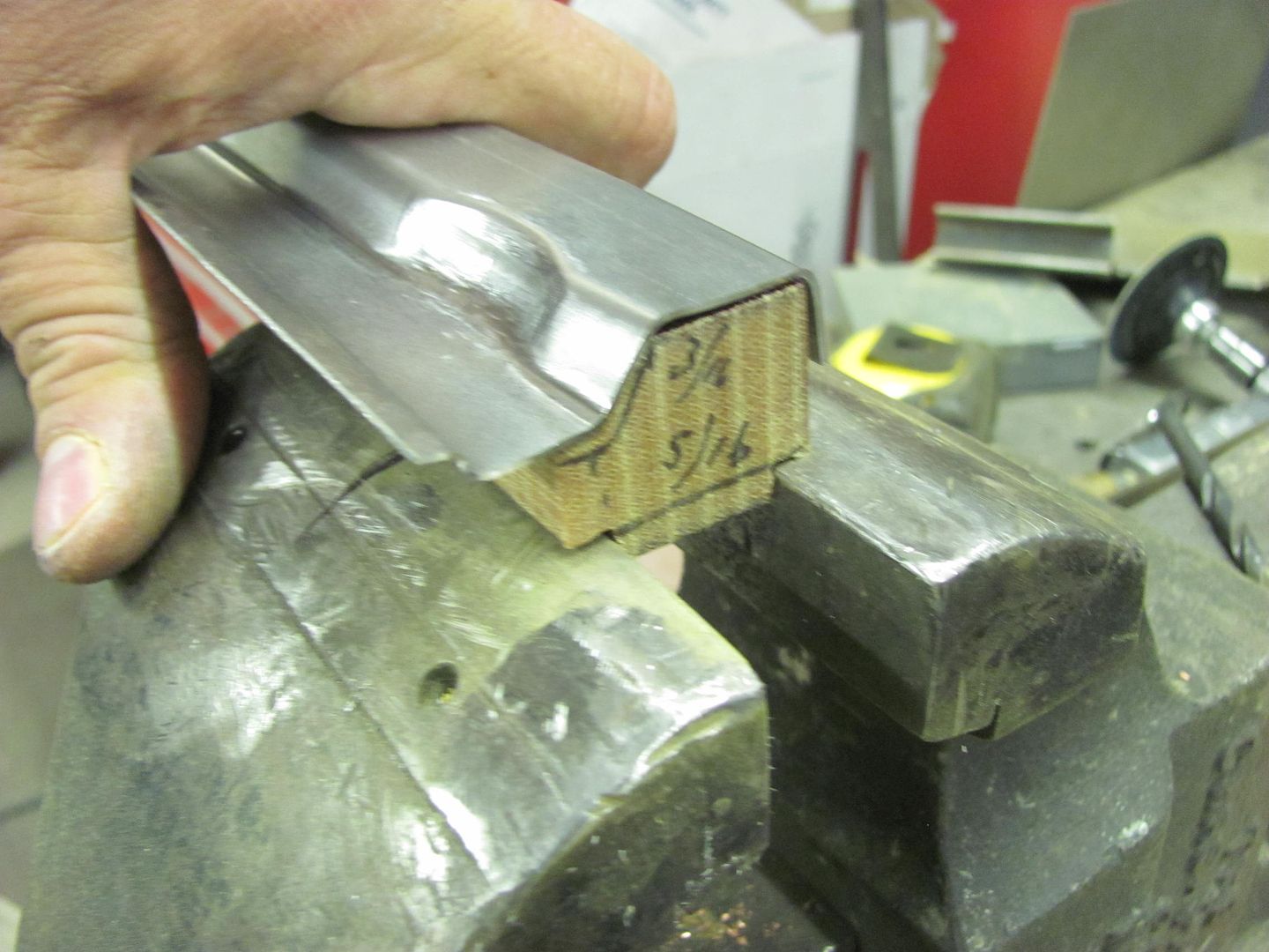
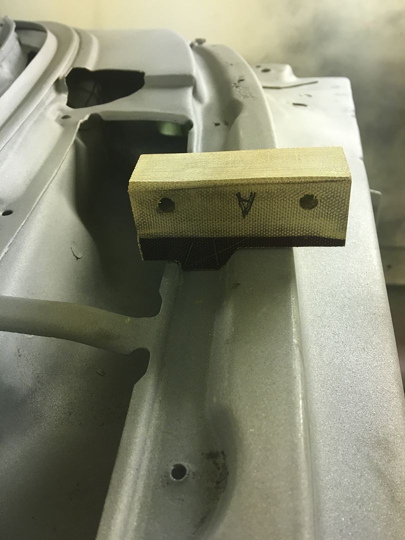
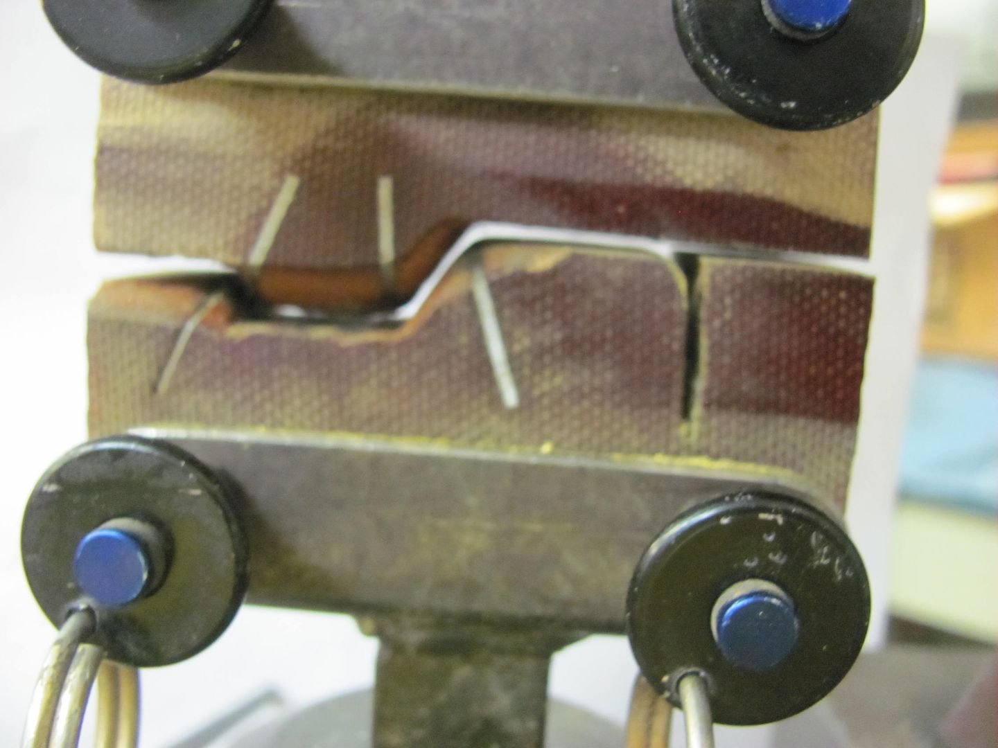
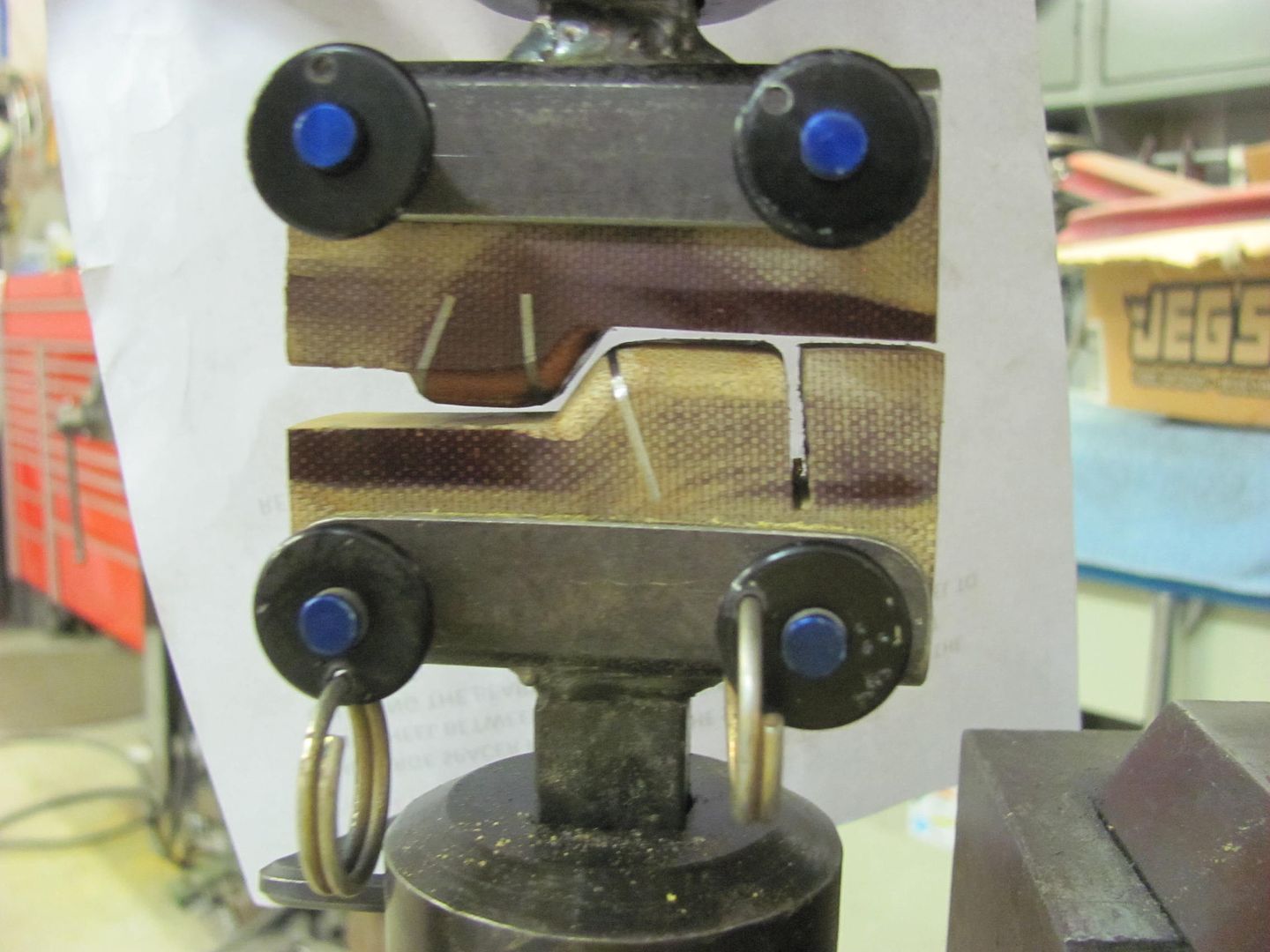
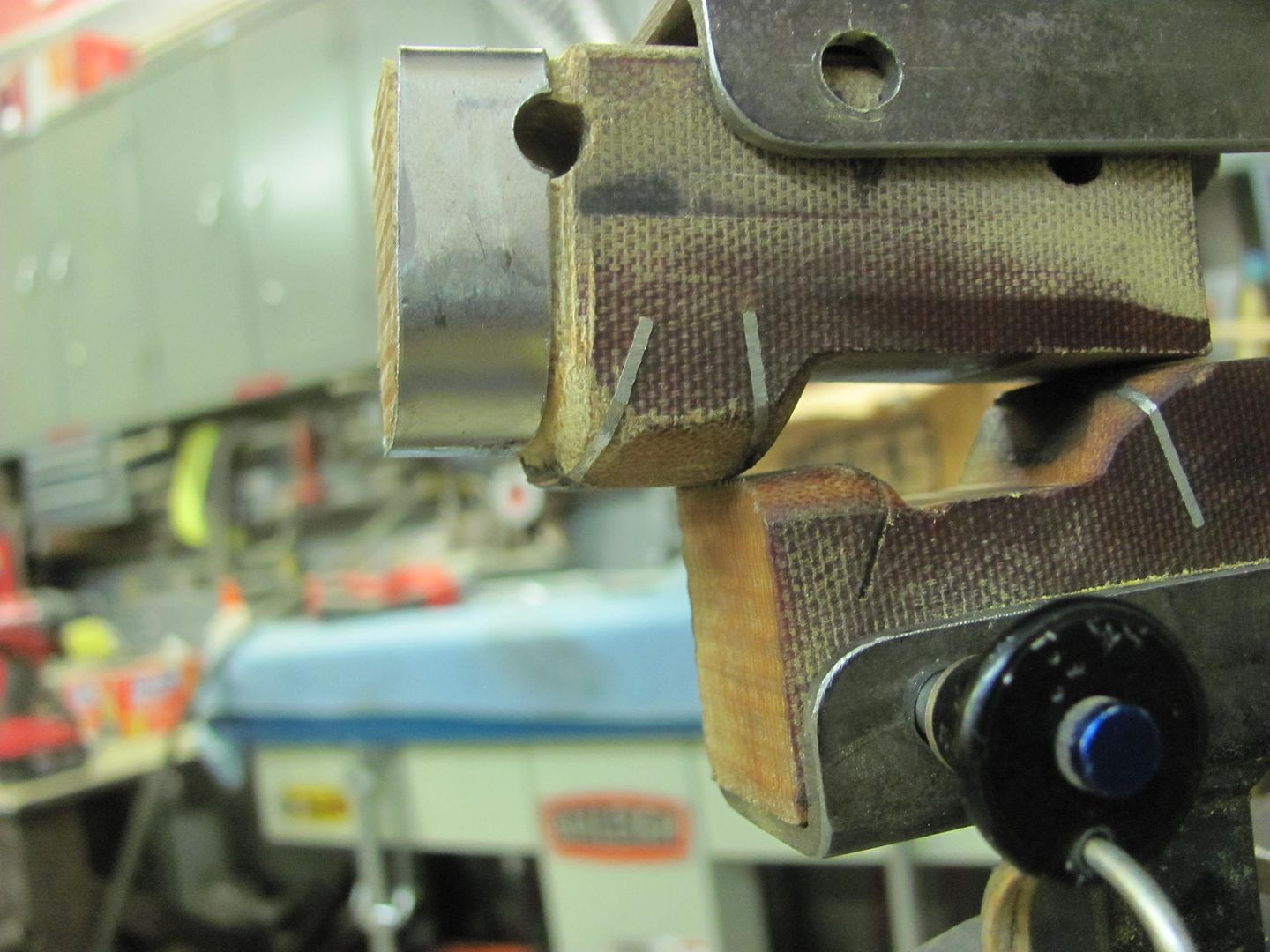
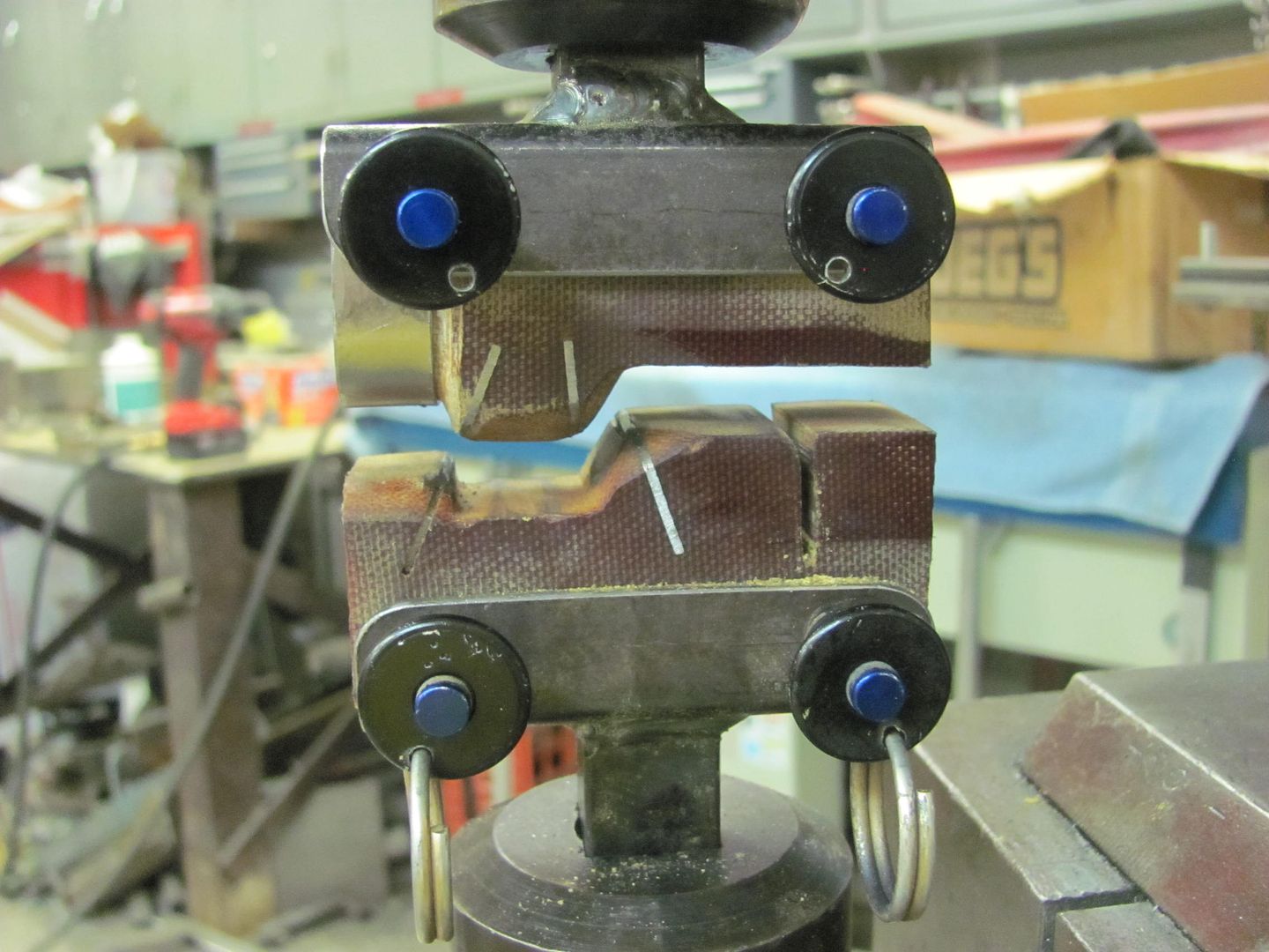
This is a piece that was destined for the trash bin at my employer approx. 20+ years ago. I couldn't bring myself to throw it away, and have been dragging it around since. Just started using it to make dies for the Lennox a couple/three years back. It is classified as a GRP, and although it is very stout, I believe there is some compression that occurs in those high stress areas like trying to push metal into a corner. So adding a bit of steel in there seems to help that shortfall. I'm down to about a foot square of material left, so I may need to start looking myself.
And here I was hoping you're picking up ideas...
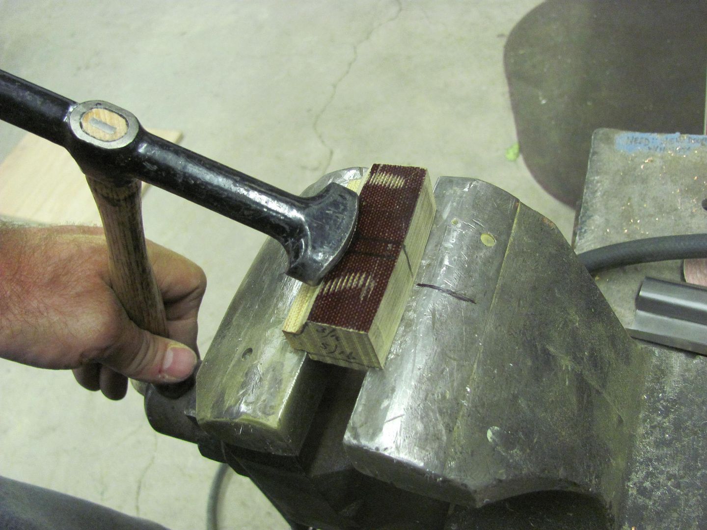
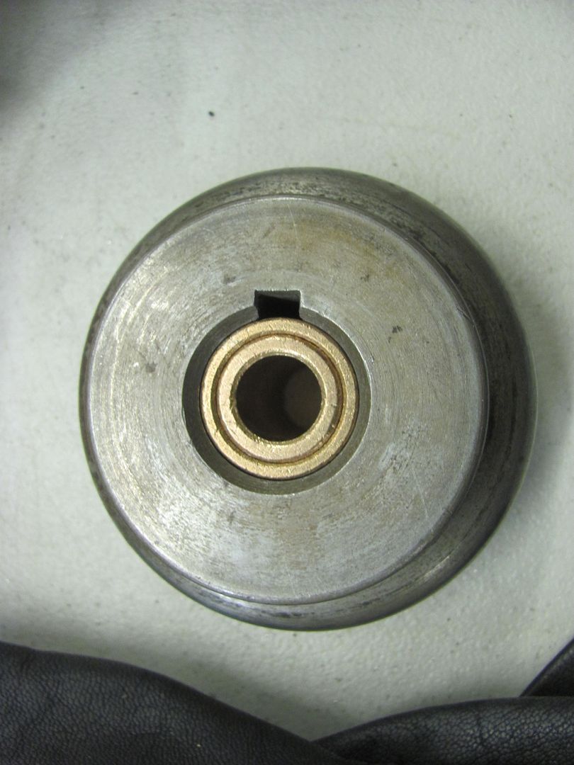
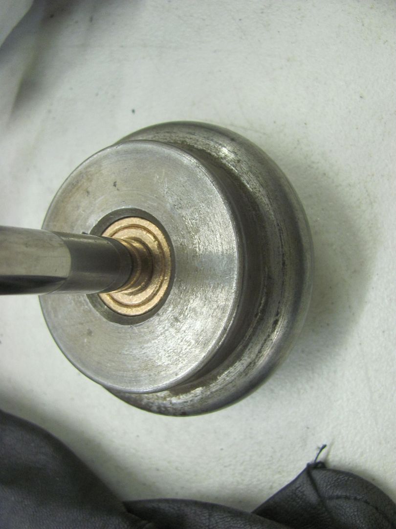
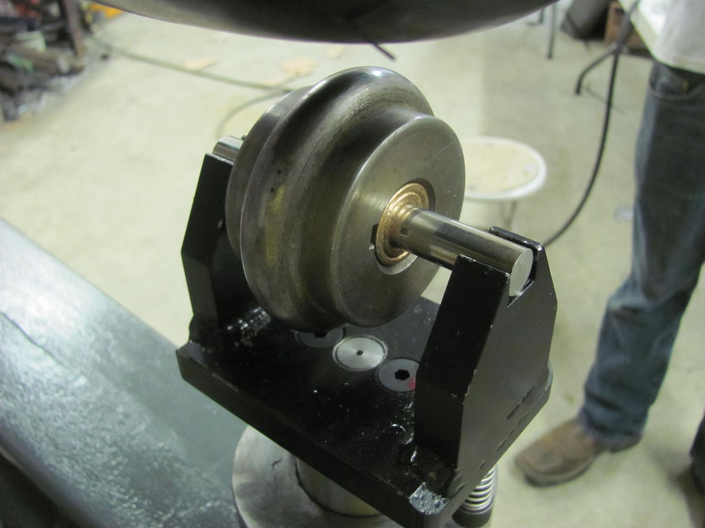
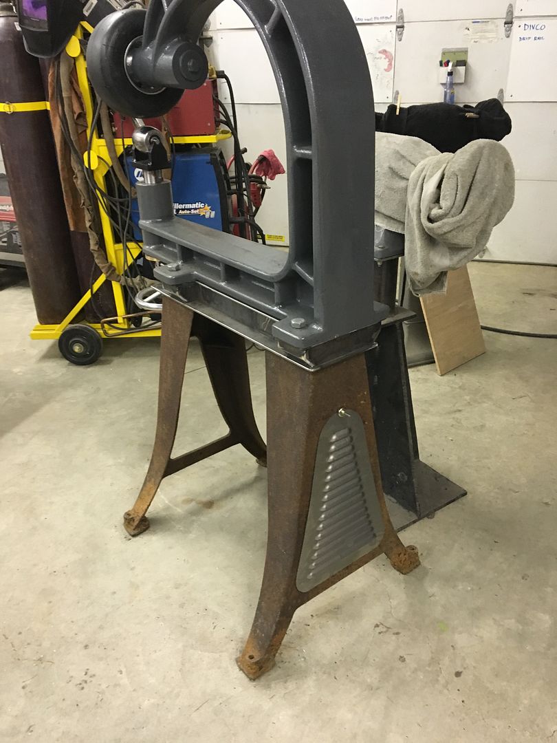
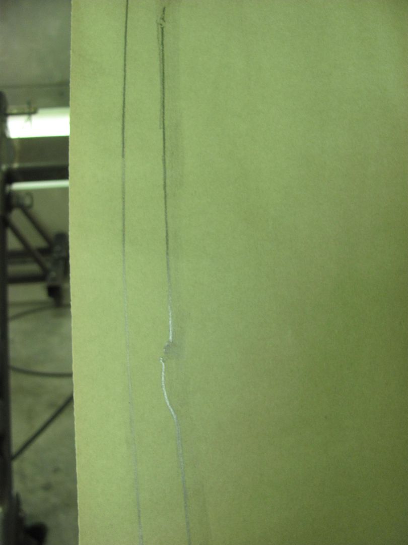
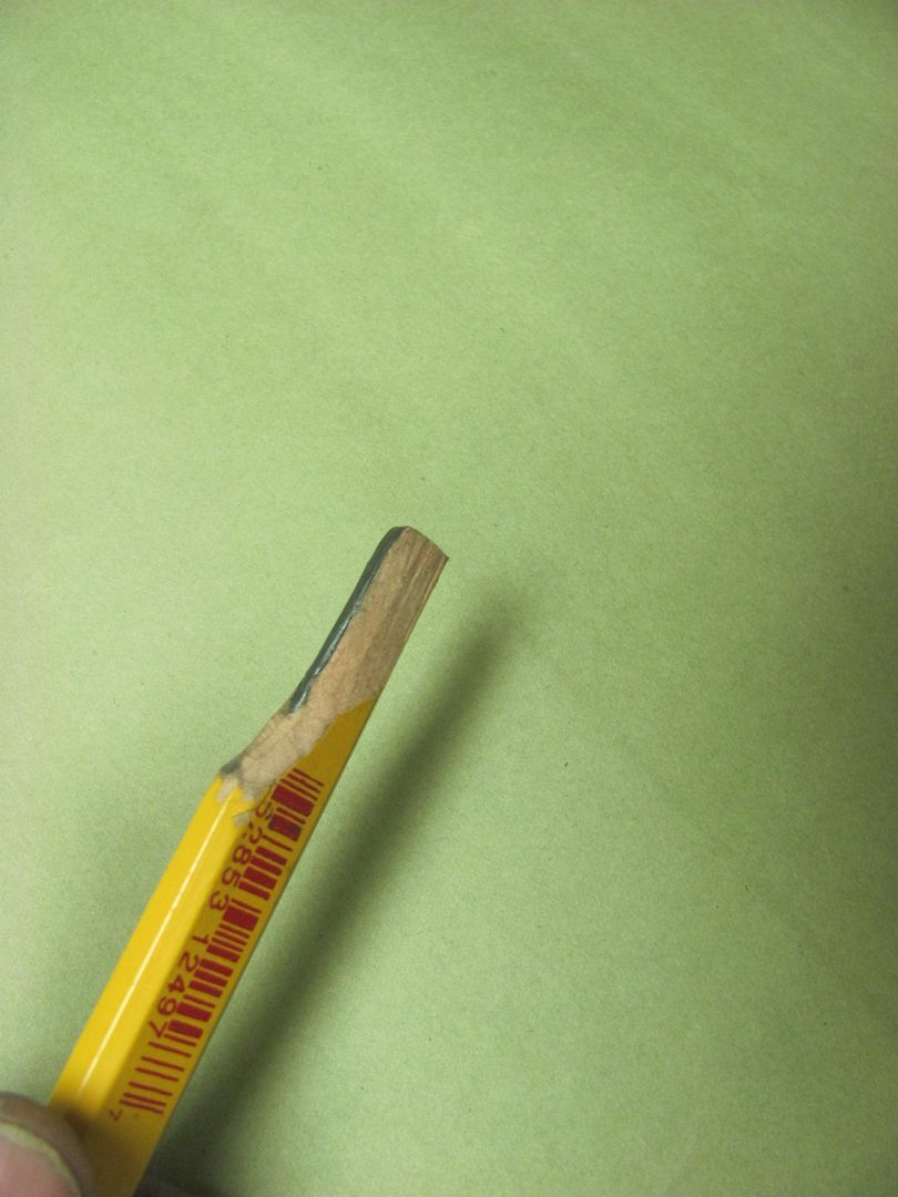
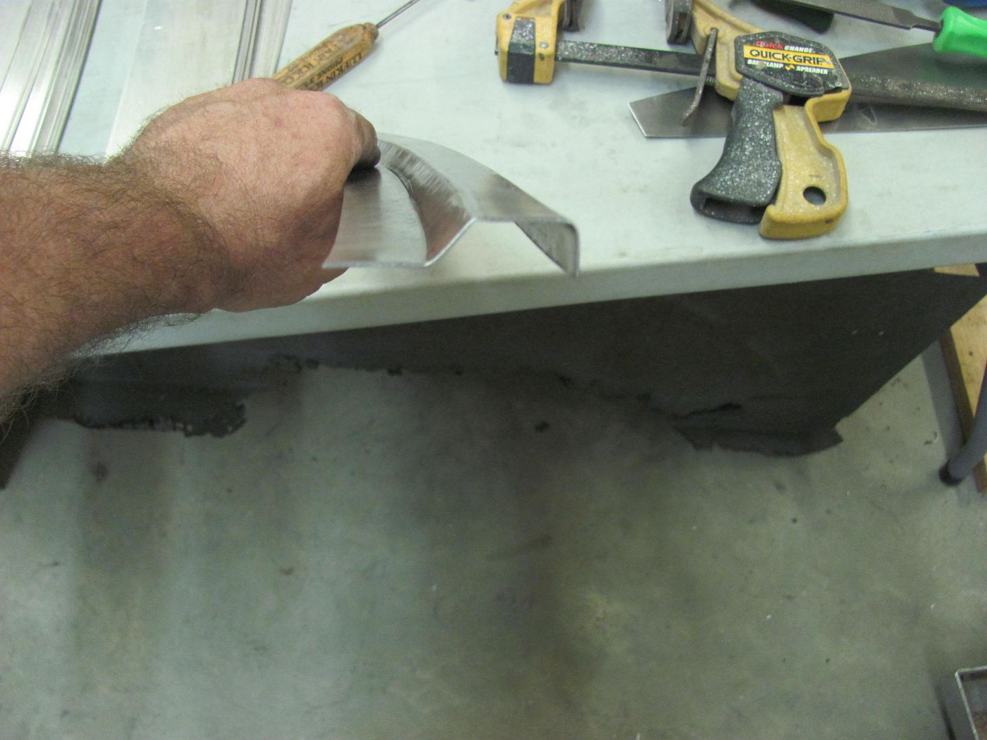
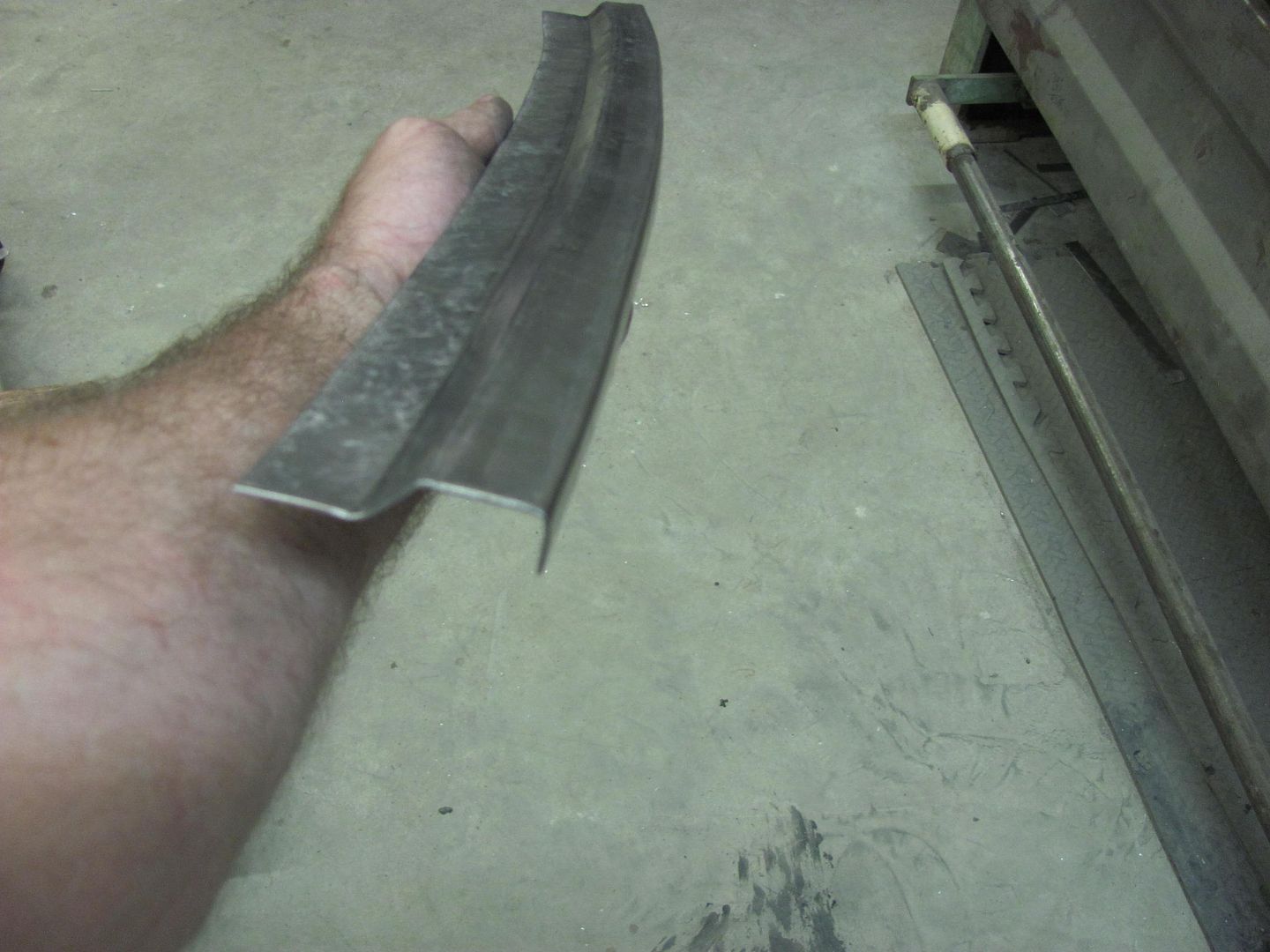
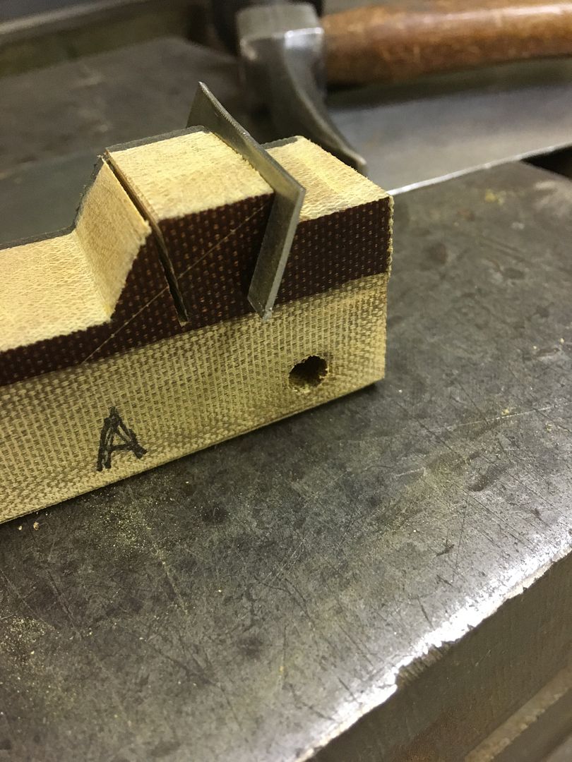
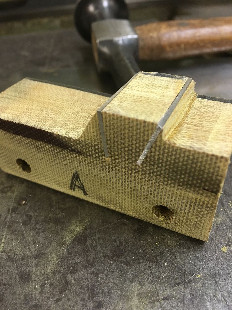
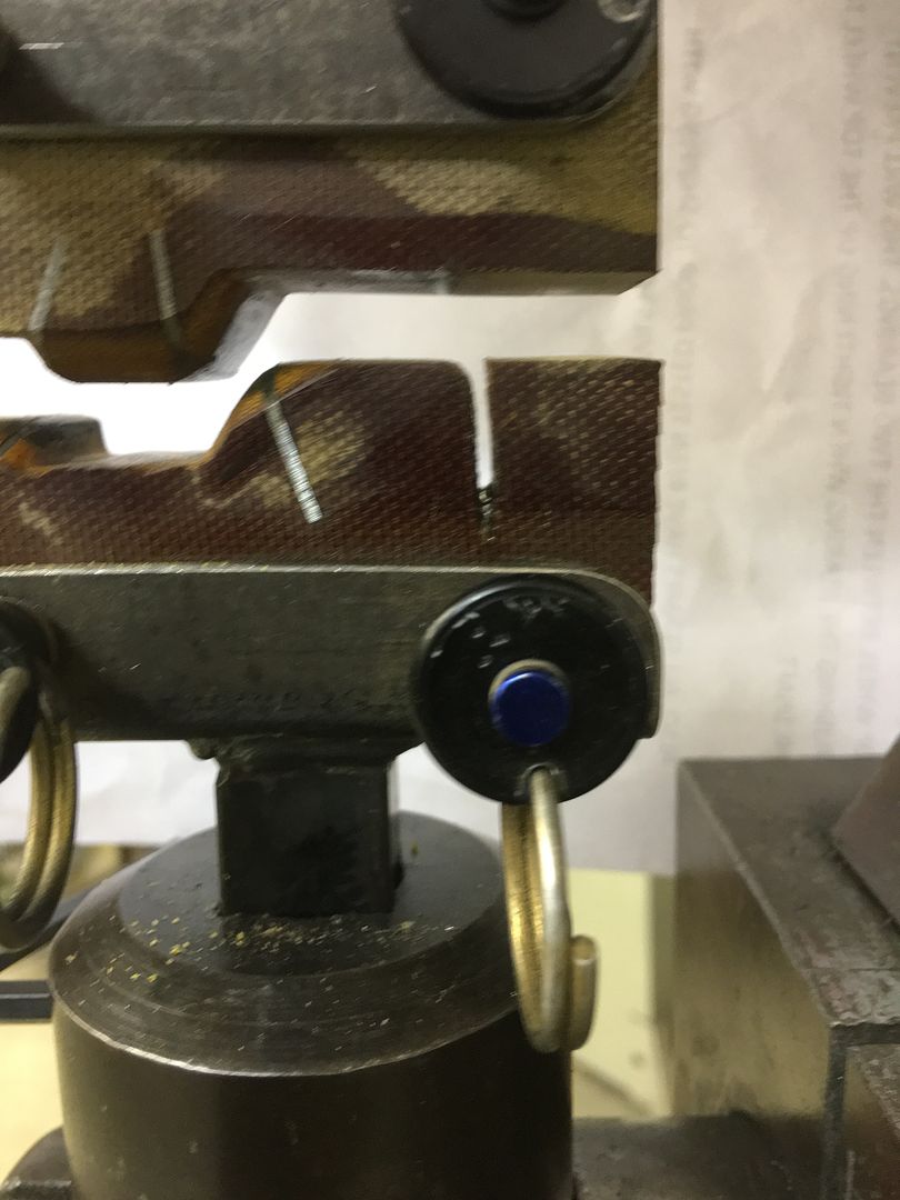
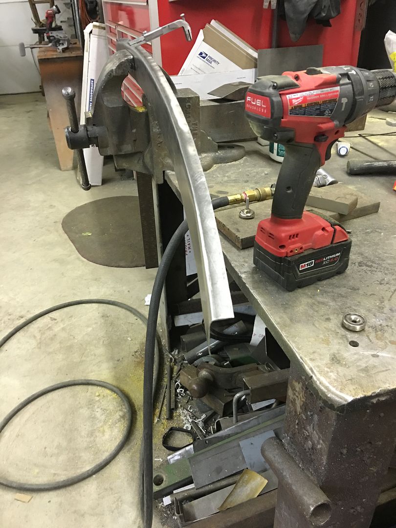
This tool here ANYBODY can make....
Great stuff Robert. Thanks for sharing your expertise.
FWIW you've given me the knowledge and confidence to try some small fab projects of my own and they're coming out OK. Already busted one of those cheap HF metal brakes (worked well enough for $20 until I pushed it beyond what it could reasonably do). Now on the lookout for a proper Pexto, Diacro, etc.
Robert,
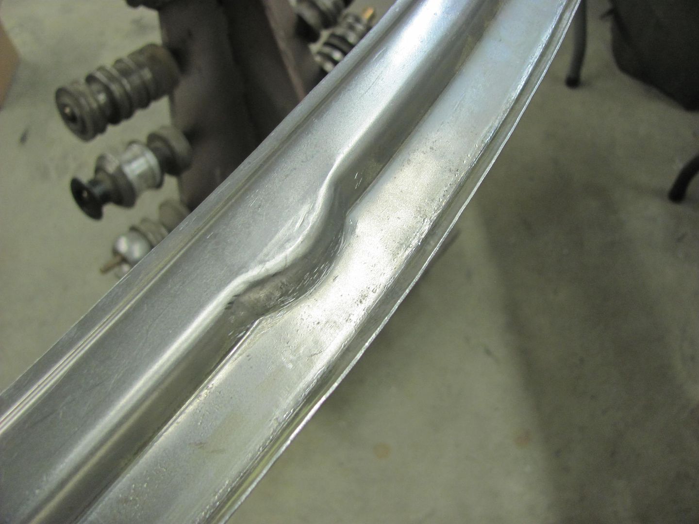
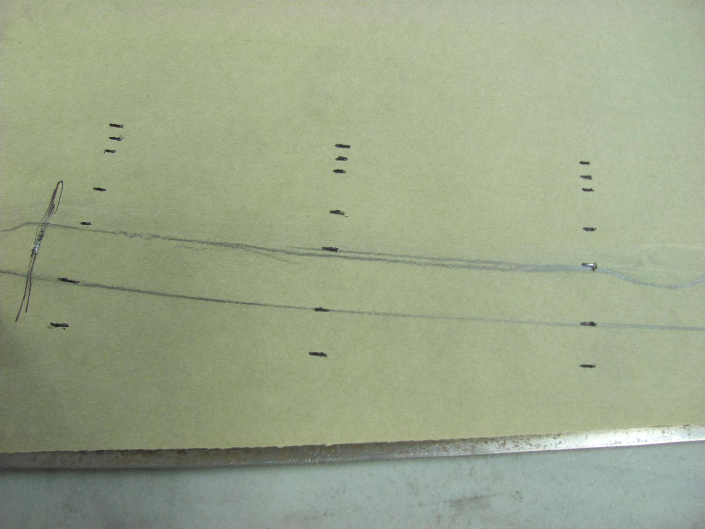
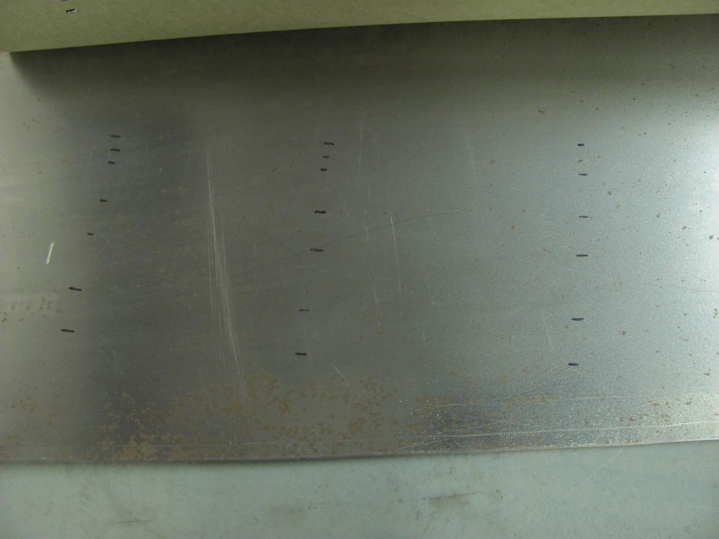
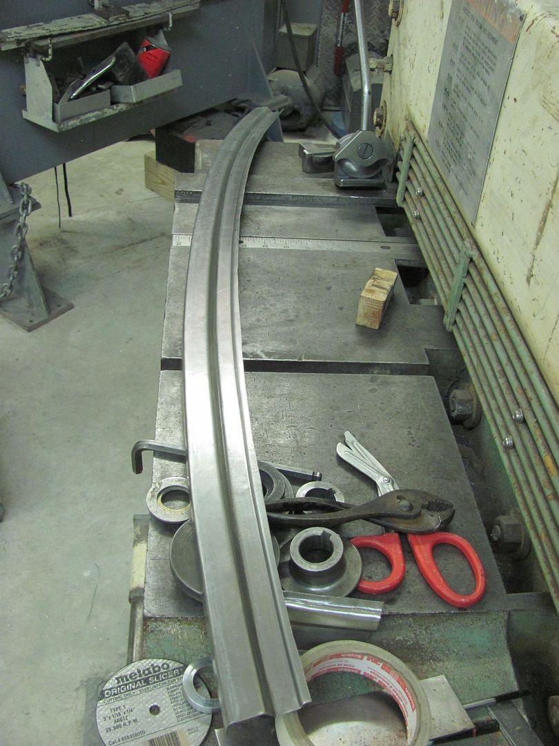
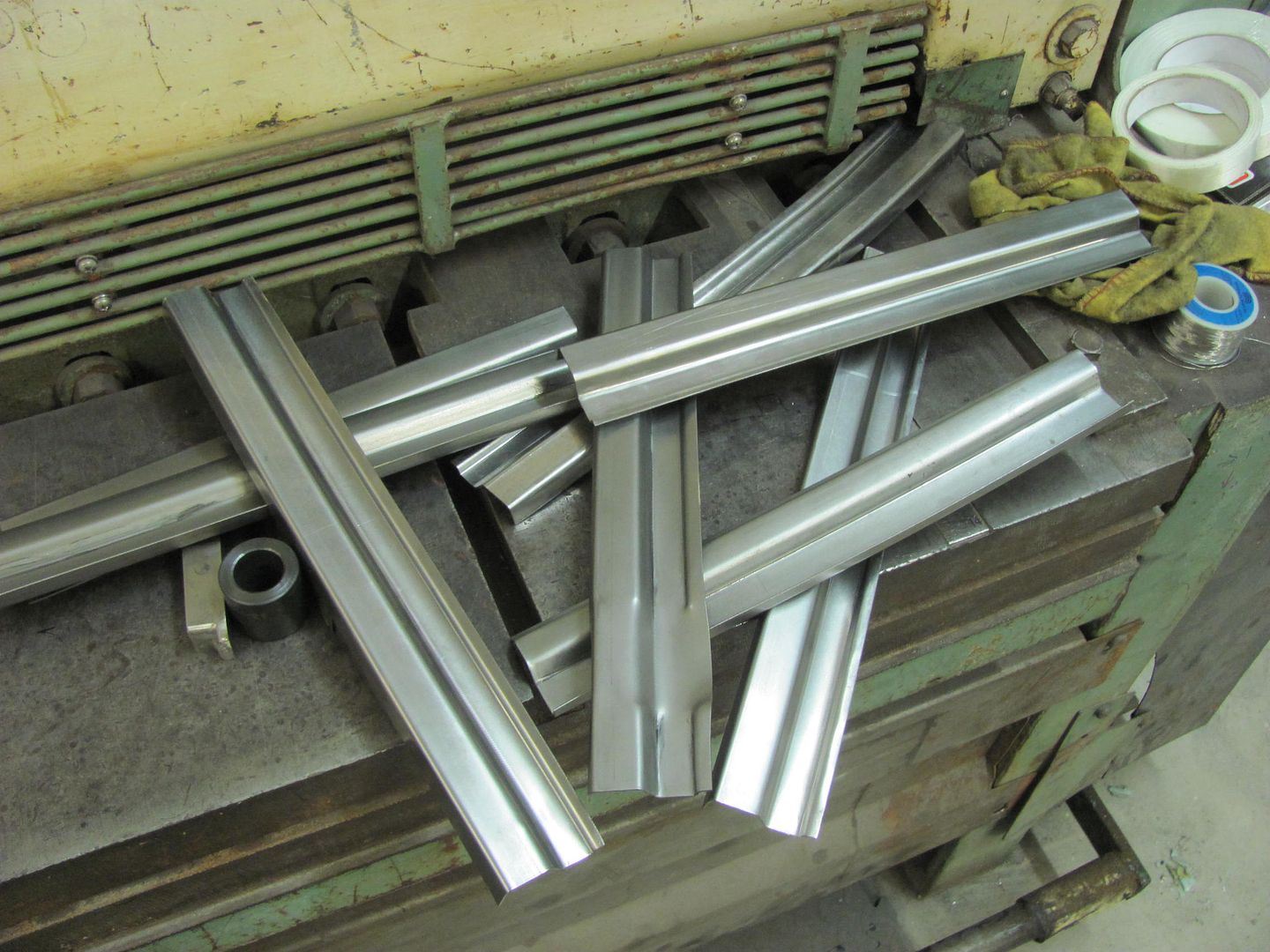
I think one of the most informative pics lately is the pile of pieces that it took to refine the process 'til it was good. I think folks don't realize how difficult it can be to develop a process that makes a part. Sometimes it goes quickly and other time not so much. I guess the key is the past experience that allows you to see what's wrong and know what it will take to fix it and get it right fairly quickly. Not something that you can learn in an afternoon (or at least I can't). It's not like on TV where the crew goes to lunch and Billy whips up a fender while they're gone and has it bolted on when they return.
I have to agree with EdT. I learned more from your mistakes pile then i did from the finished product. It also brings this type of work into Perspective, its not just a 1 time and done kind of project. Its a work at it and keep working at it. Keep up the Amazing work!!