
You are using an out of date browser. It may not display this or other websites correctly.
You should upgrade or use an alternative browser.
You should upgrade or use an alternative browser.
MP&C Shop Projects
- Thread starter MP&C
- Start date

larry4406
Well-known member
I find your work to be impressive! Case in point, the repair to the inner window frame just documented. The repair will never be seen again, but the repair quality is no different than that of a finished exterior panel.
56vette461
Well-known member
Thanks Larry! I find pieces like these good practice for making the exposed parts that really count. Taking shortcuts here only limits our experience in learning to form new shapes.
Amen to the practice and always doing it right. Learned from my dad.
BORING HOP YARD
Well-known member
Robert, you hit the nail on the head. Its what I call working at the next level.
Thank you for showing and sharing, your work inspires me to try and work to that next level. I still think to myself " what would Robert do" when faced with a difficult situation on my 56.
Thank you for showing and sharing, your work inspires me to try and work to that next level. I still think to myself " what would Robert do" when faced with a difficult situation on my 56.
Thanks for the comments guys!
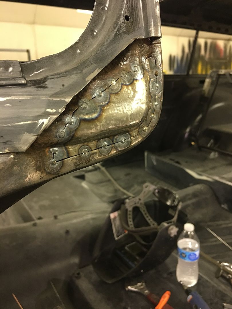
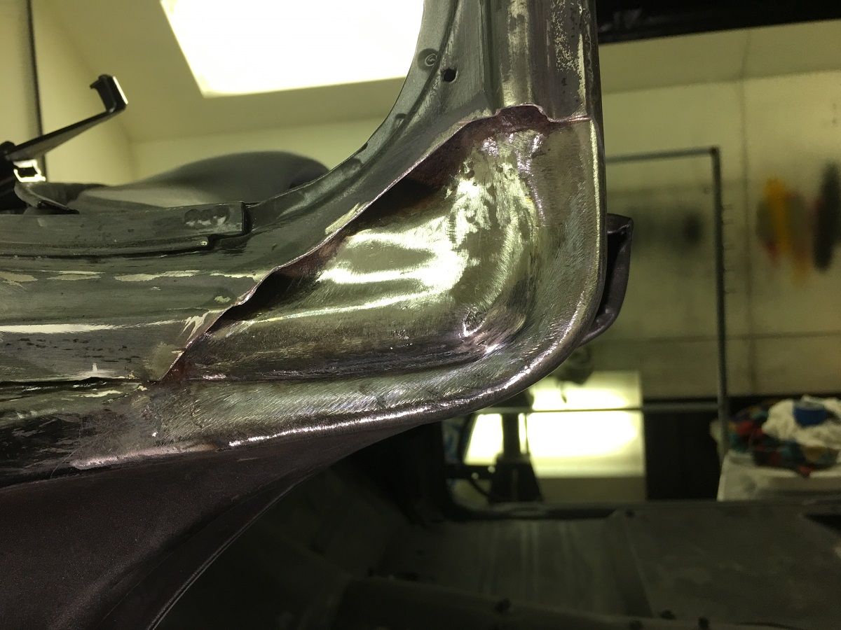
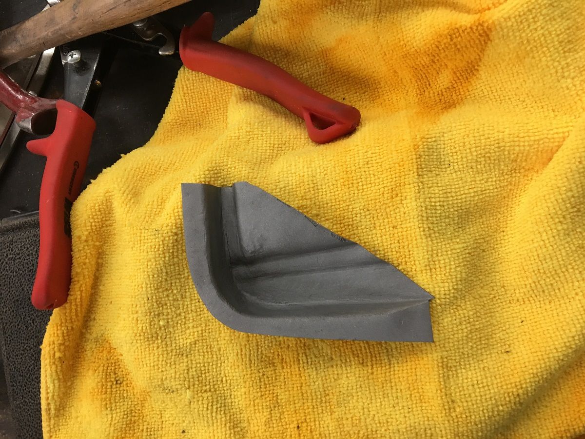
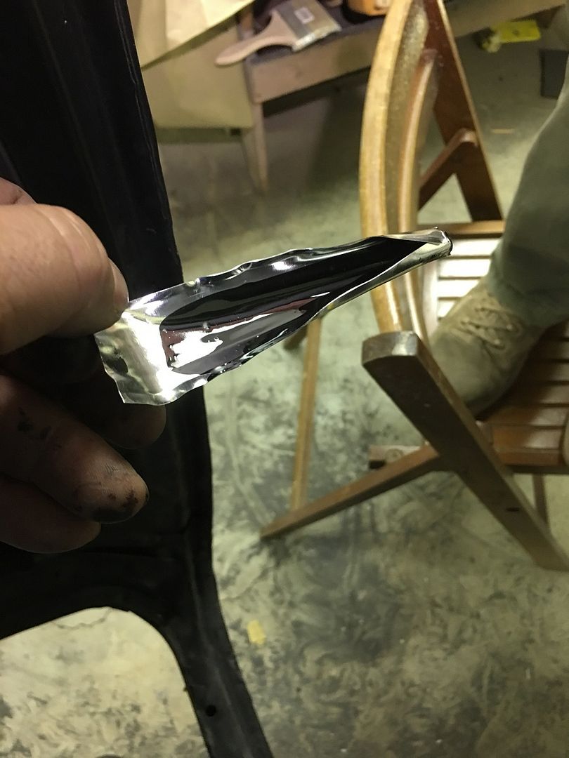
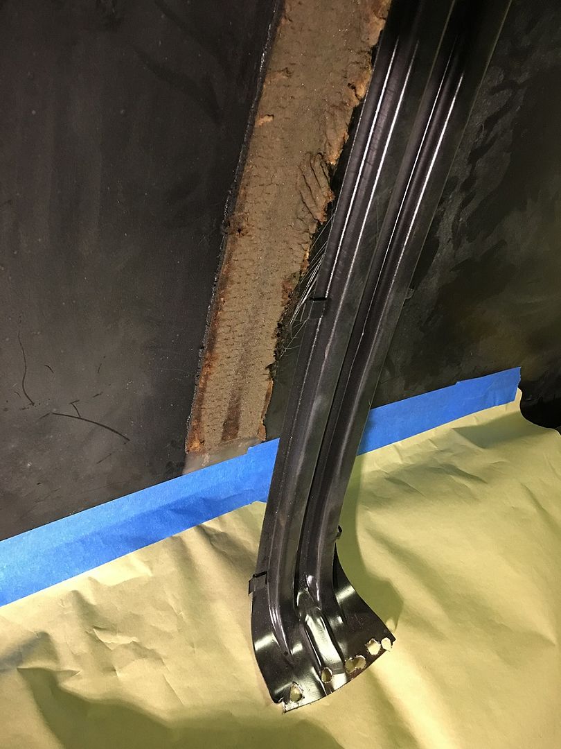
Now to get our outer patch fabricated.. The corner is going to need a GRUNCH of shrinking.. We started on the Baileigh, but the dies are only going to get us so far. So some tuck shrinking with some heat for persuasion was used..
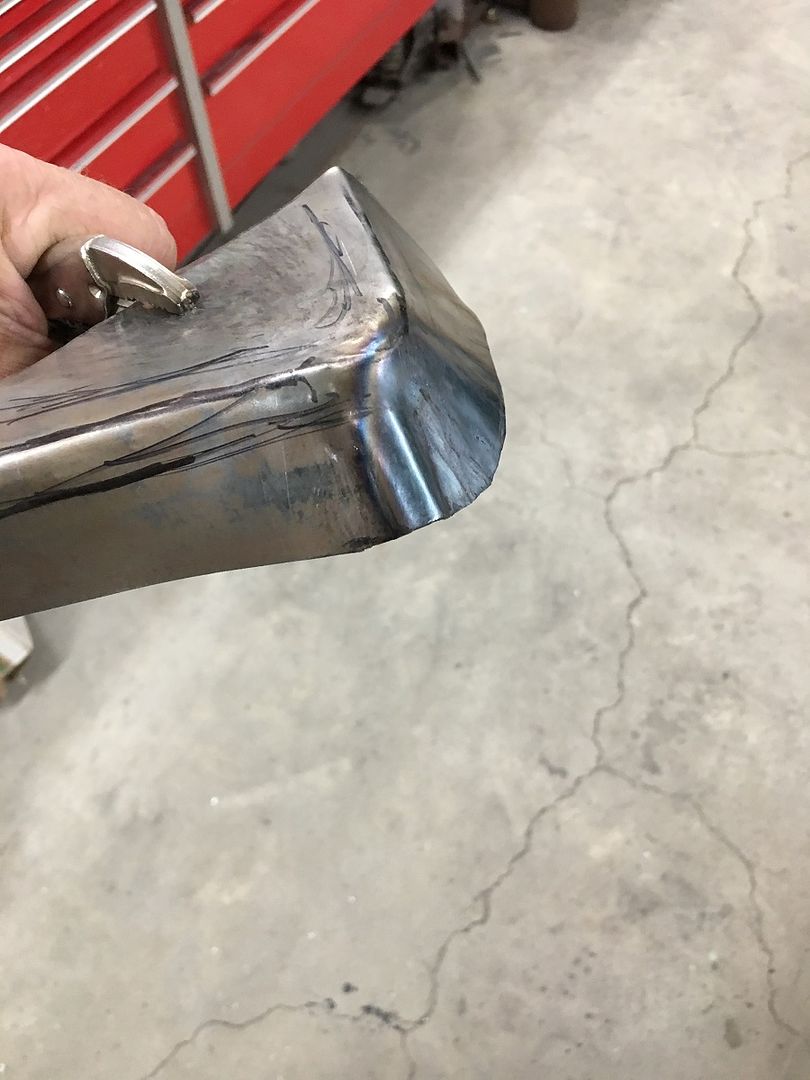
A tipping wheel in the bead roller was used to mark our bend line, and an upper press brake die used as an anvil to hammer the flanges over..
Some hammer action to stretch the corner flange so it will tip the full 90*
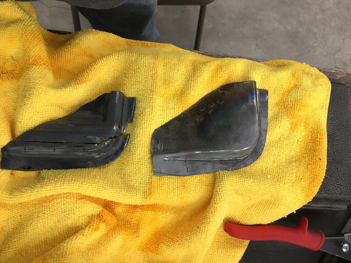
I missed some in process pictures here, but various hammers, anvils, punches, and other implements of destruction were employed to give us our basic shape...
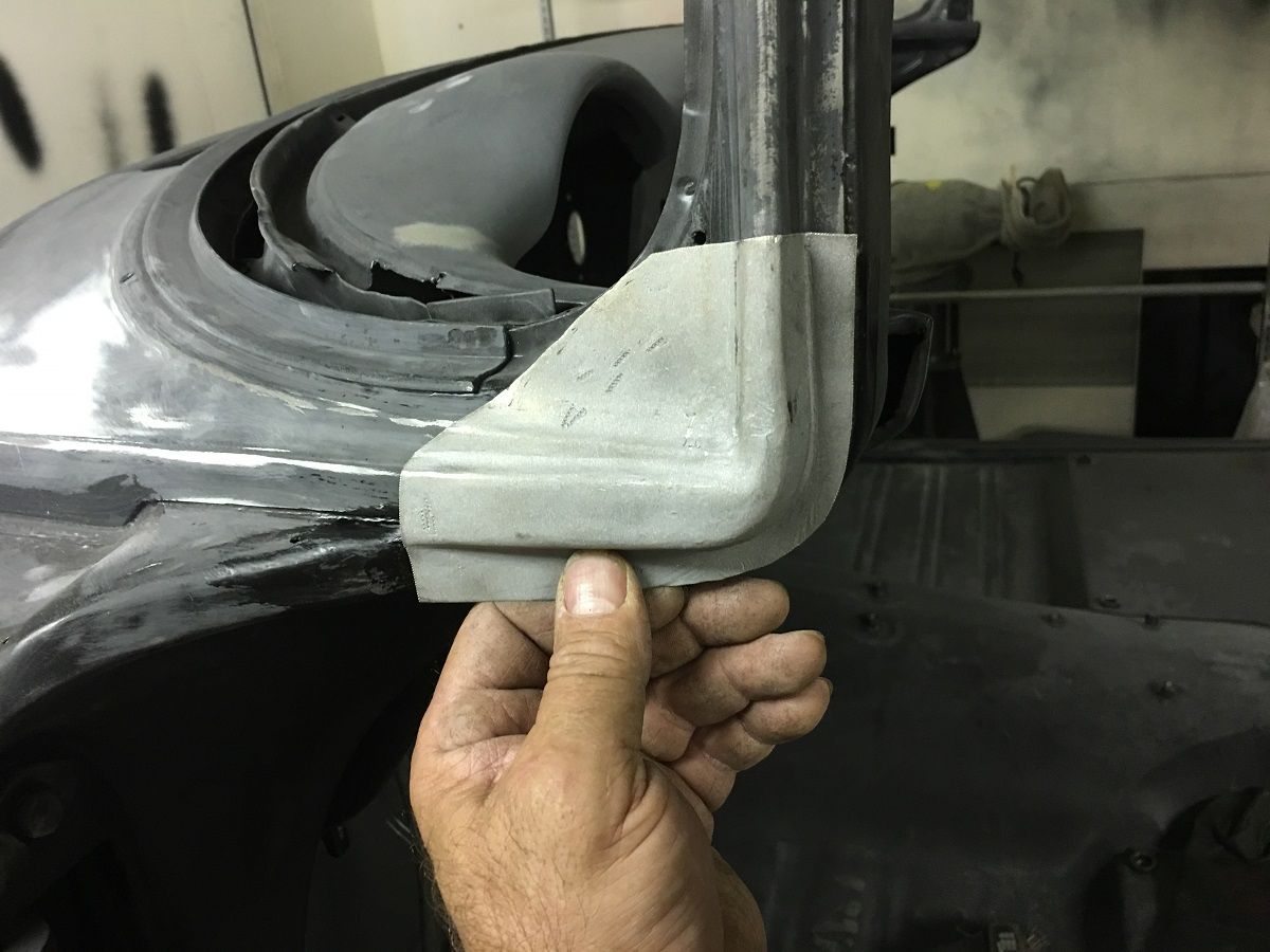
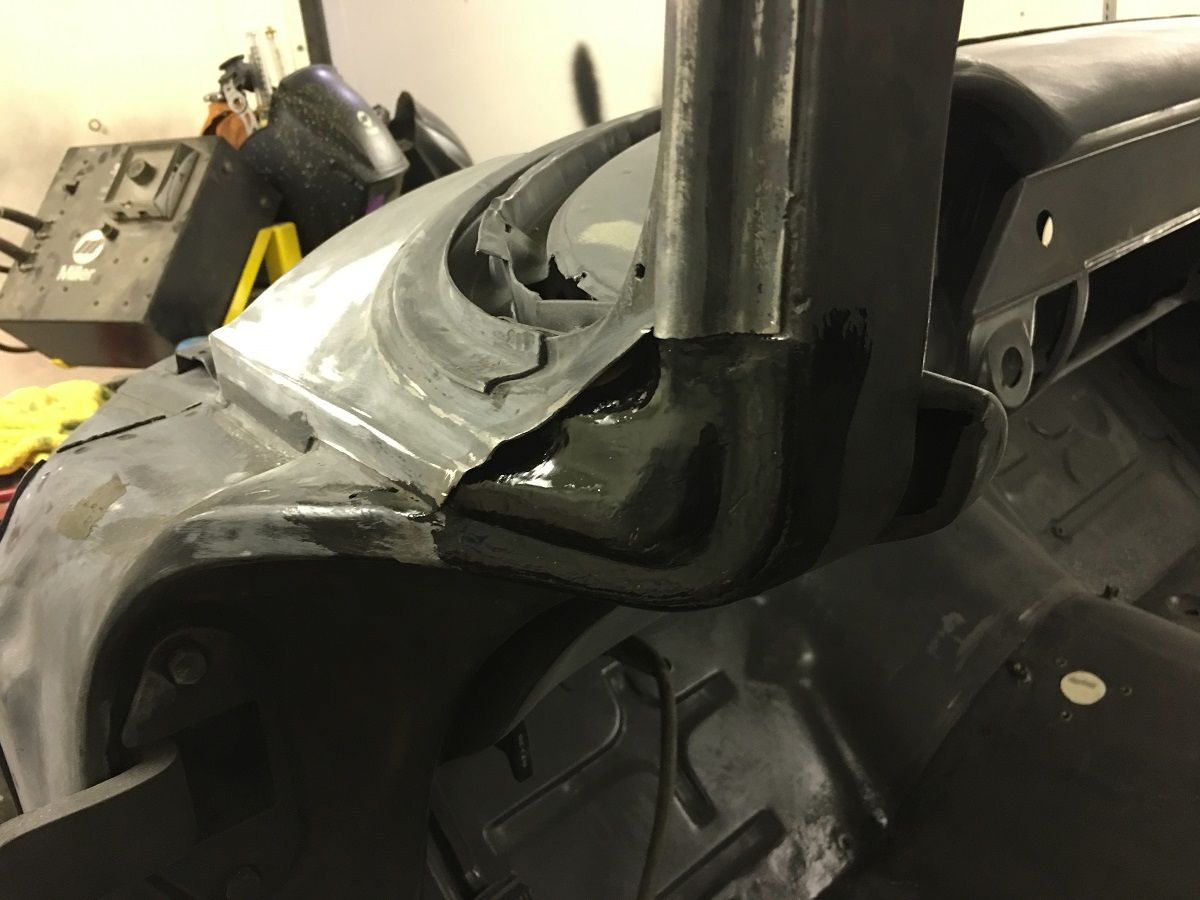
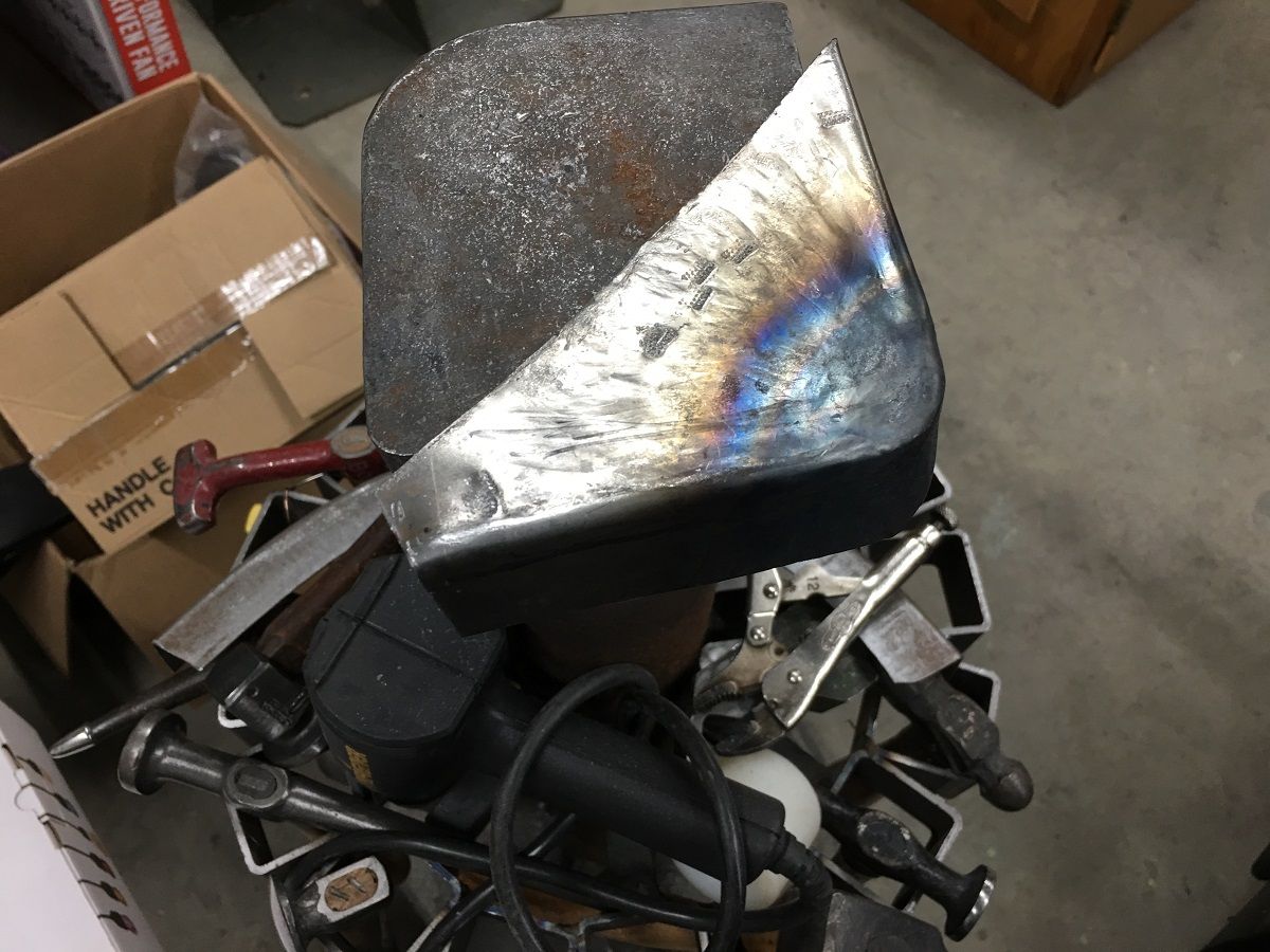
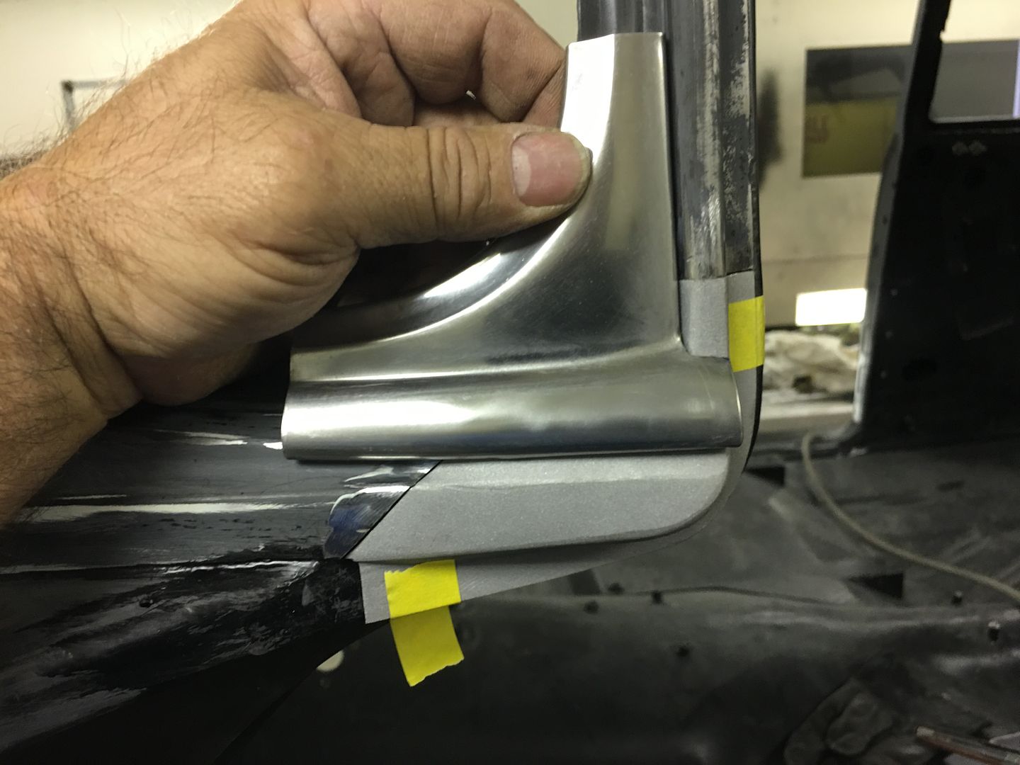
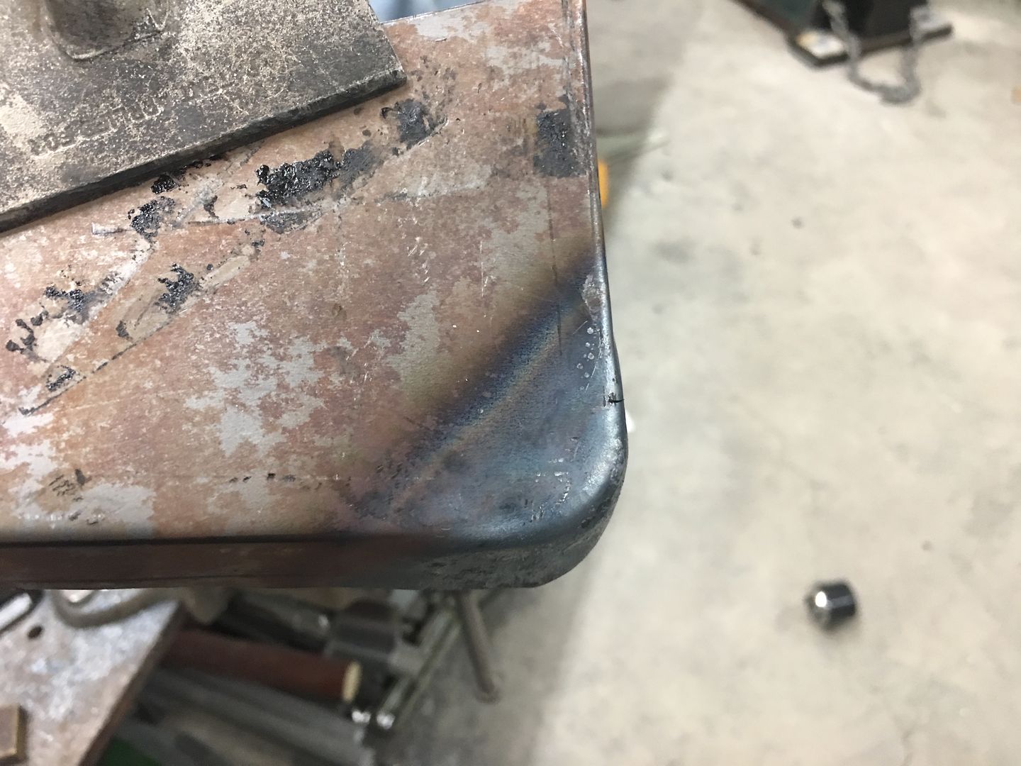
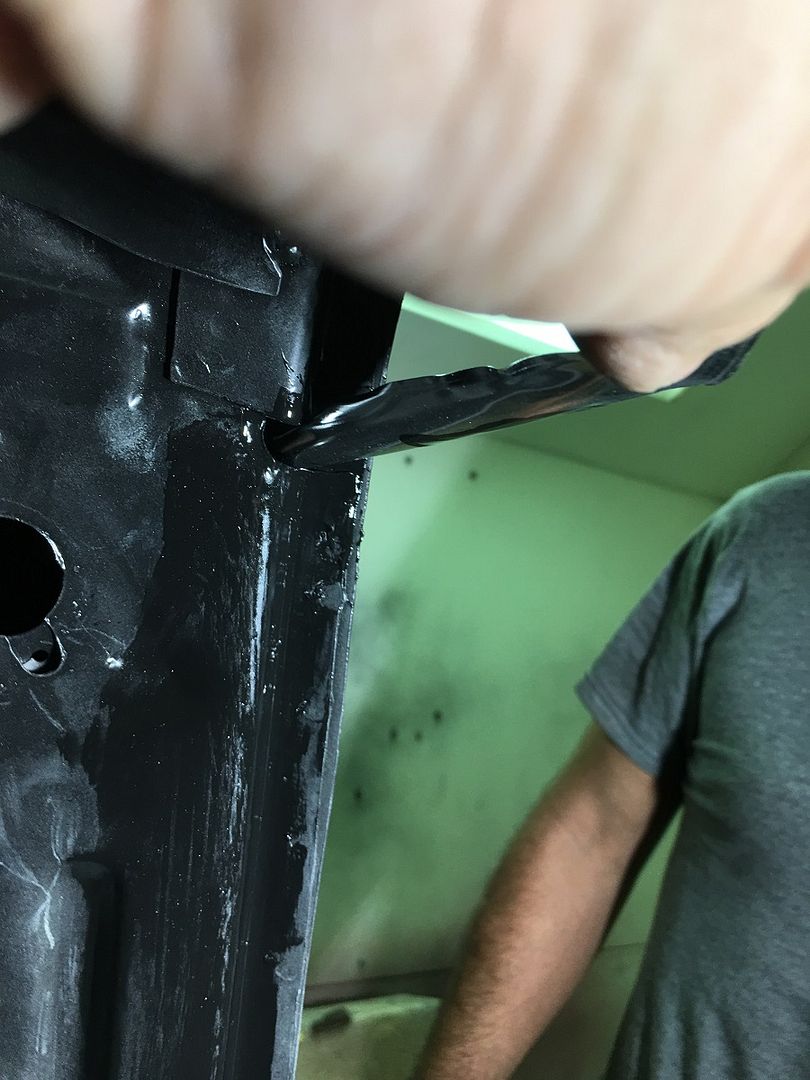
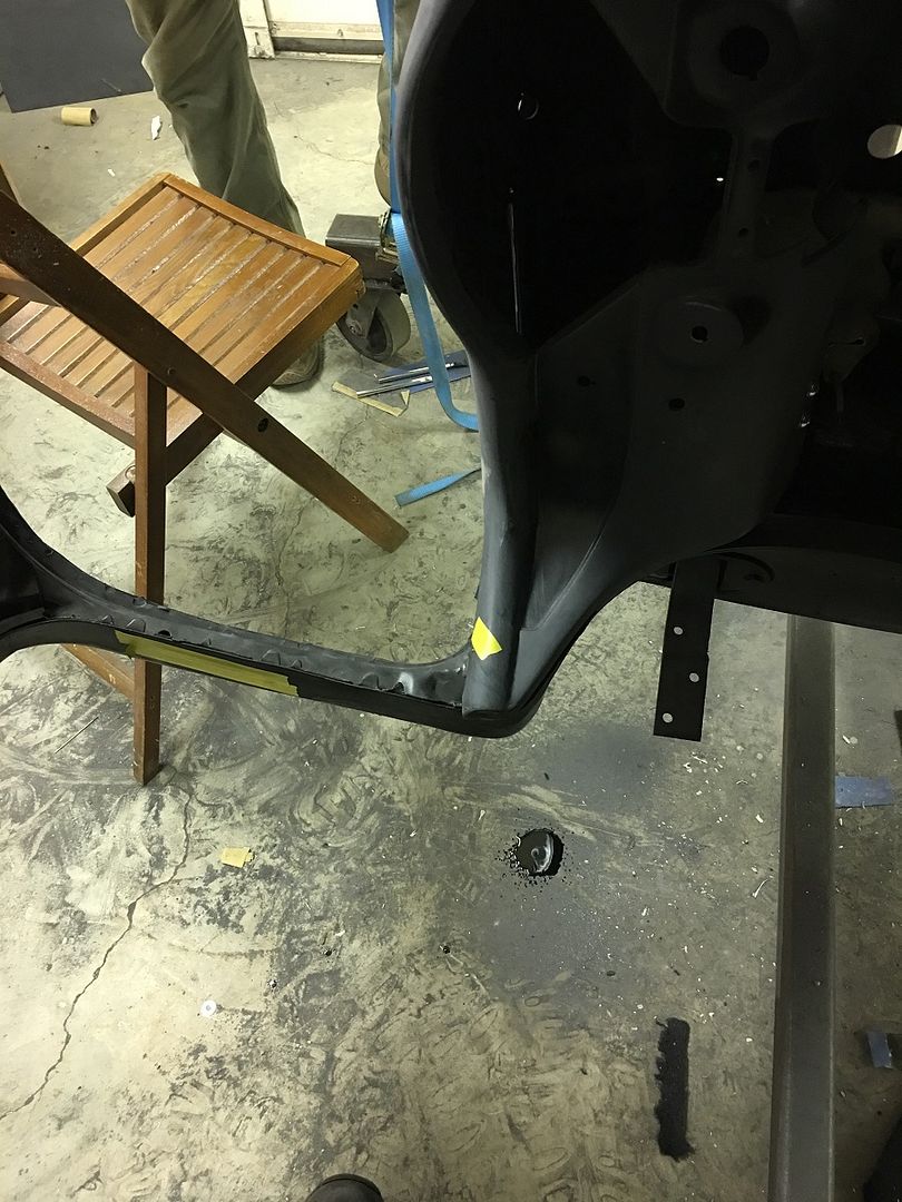
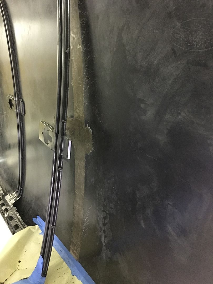
After a bit of fine tuning, it is trimmed and fitted into the A Pillar...
and the windshield stainless is test fit for good measure..
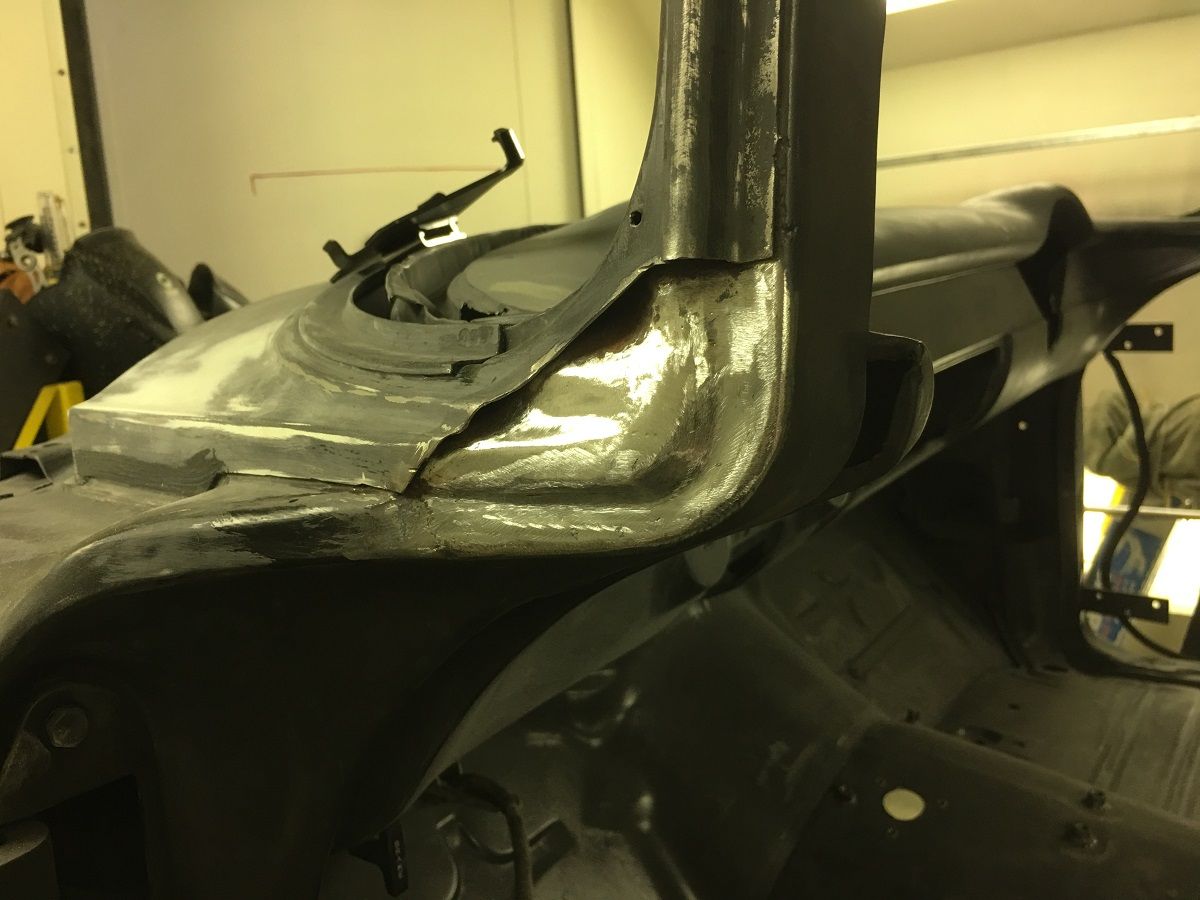
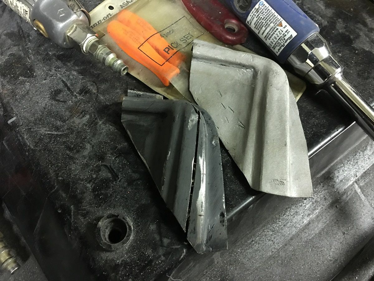
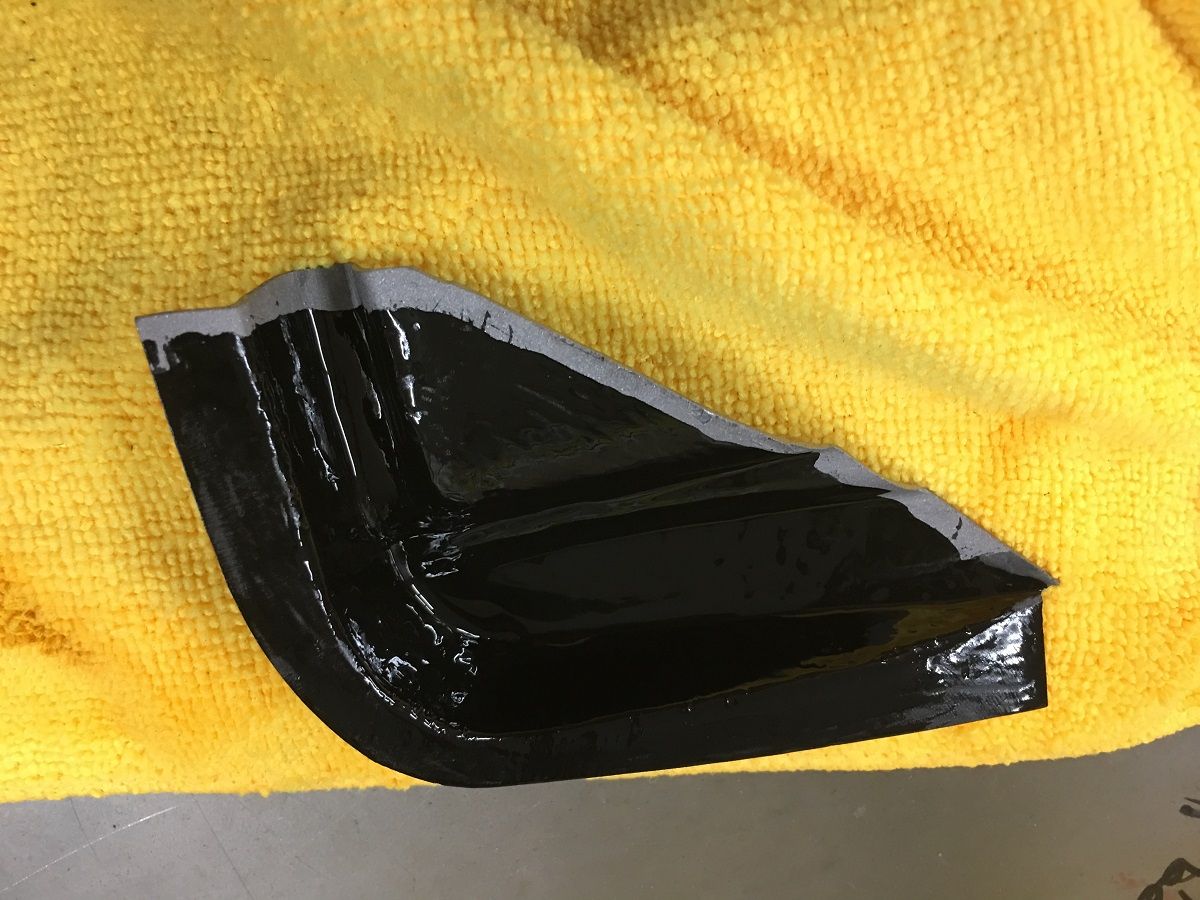
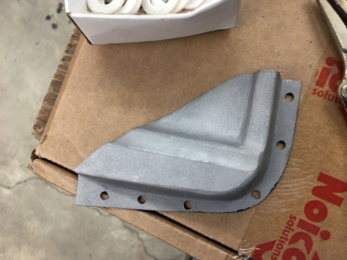
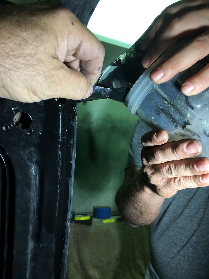
The finished piece is media blasted (Barton Garnet) so the SPI epoxy primer will have a good bite. The inside is primed as a bit more preventative measure over factory....
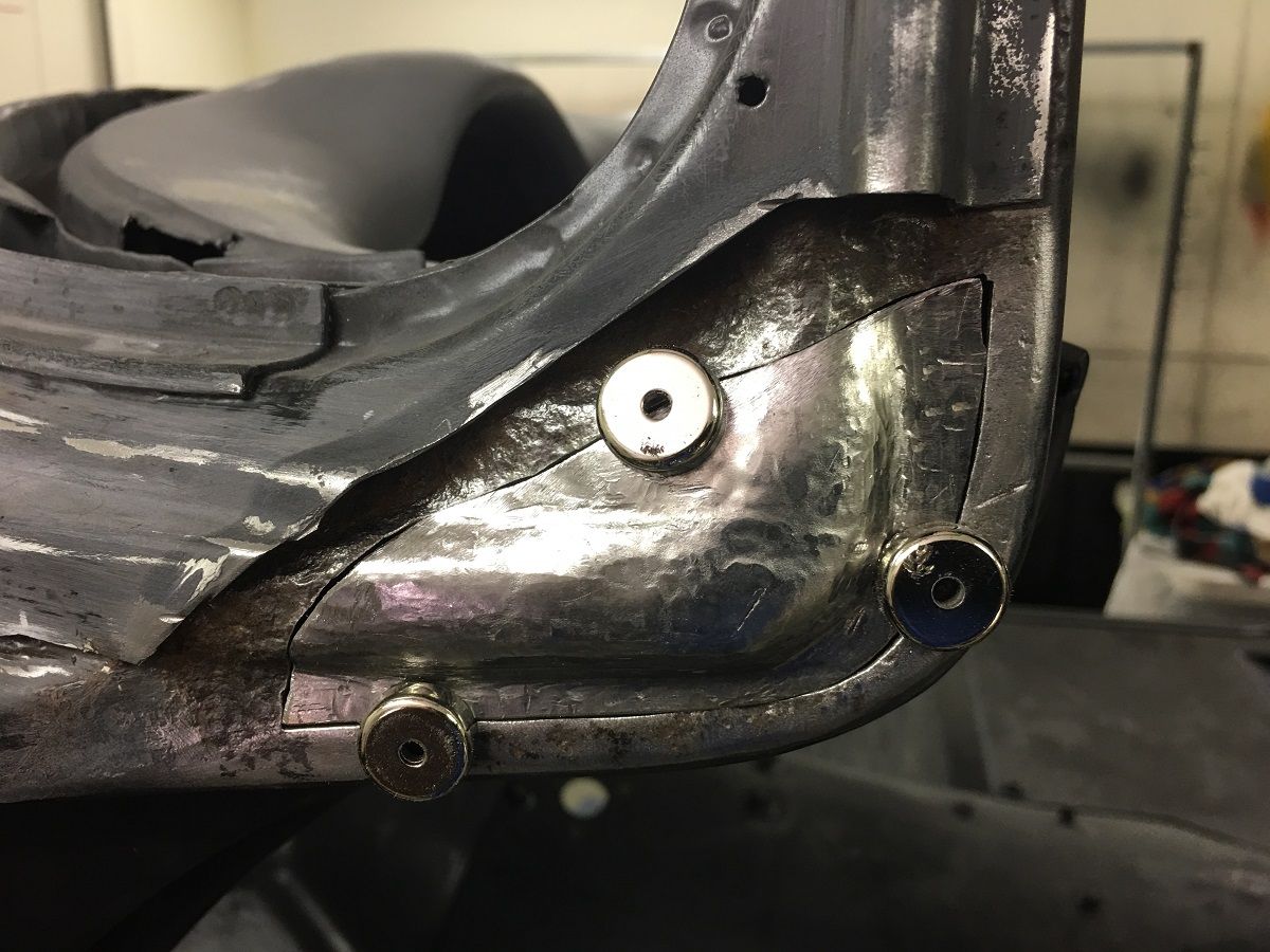
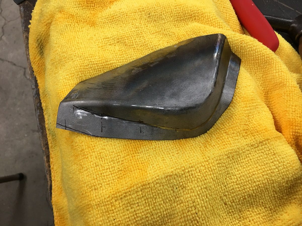
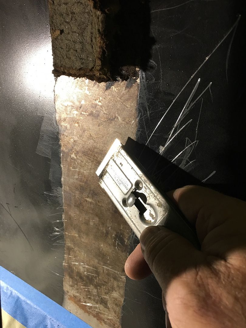
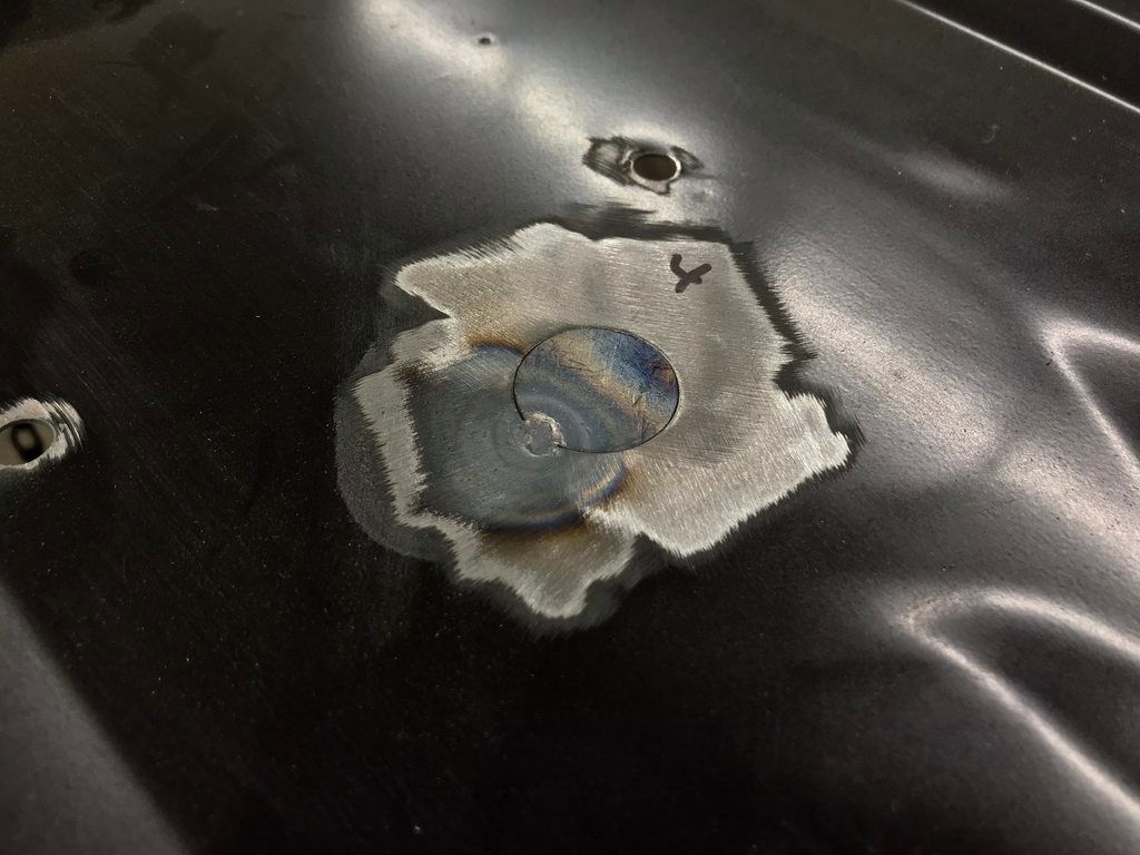
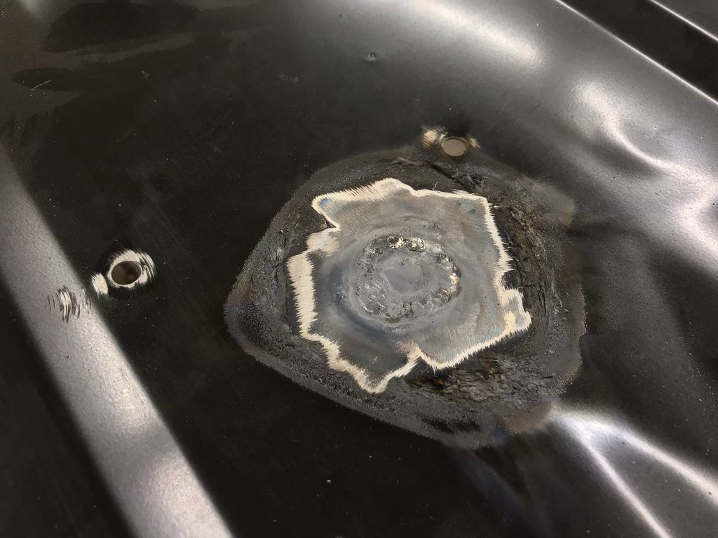
The flange is quite small compared to what we normally plug weld, so we opted for a .169 drill bit to keep the heat away from the edge...
In order to clean he primer out the inside of our plug weld holes, we flattened and backfaced our drill bit to mimic an end mill....
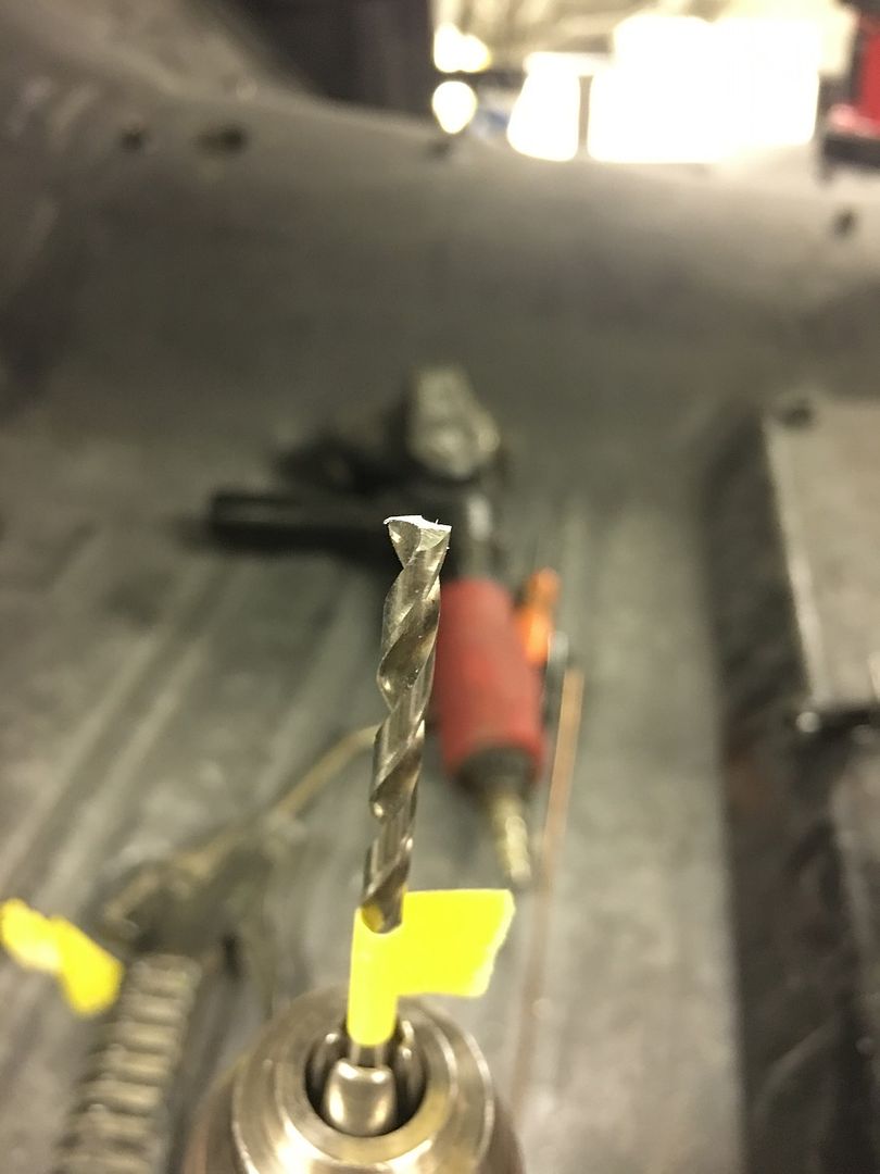
Does a good job of giving us nice clean metal for a good weld..
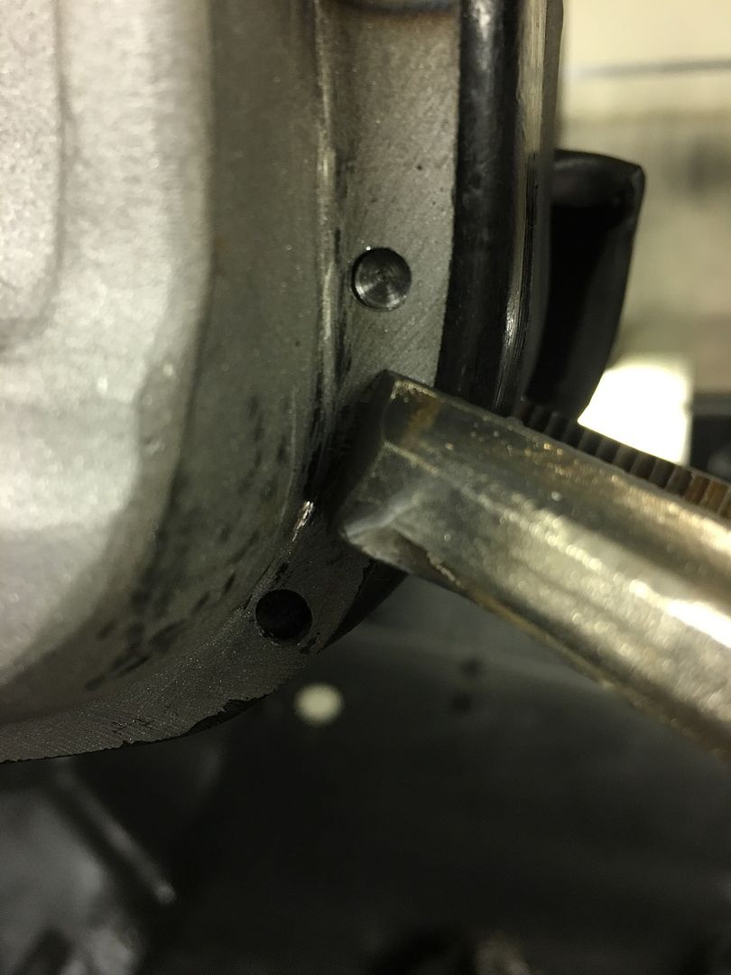

much better....
.
Now to get our outer patch fabricated.. The corner is going to need a GRUNCH of shrinking.. We started on the Baileigh, but the dies are only going to get us so far. So some tuck shrinking with some heat for persuasion was used..
A tipping wheel in the bead roller was used to mark our bend line, and an upper press brake die used as an anvil to hammer the flanges over..
Some hammer action to stretch the corner flange so it will tip the full 90*
I missed some in process pictures here, but various hammers, anvils, punches, and other implements of destruction were employed to give us our basic shape...
After a bit of fine tuning, it is trimmed and fitted into the A Pillar...
and the windshield stainless is test fit for good measure..
The finished piece is media blasted (Barton Garnet) so the SPI epoxy primer will have a good bite. The inside is primed as a bit more preventative measure over factory....
The flange is quite small compared to what we normally plug weld, so we opted for a .169 drill bit to keep the heat away from the edge...
In order to clean he primer out the inside of our plug weld holes, we flattened and backfaced our drill bit to mimic an end mill....
Does a good job of giving us nice clean metal for a good weld..
much better....
.
xtremek
Well-known member
Amazing work.

Bob Heine
ALLIANCE MEMBER
That's why we all keep coming back! One small piece for the wagon, one giant lesson for us.
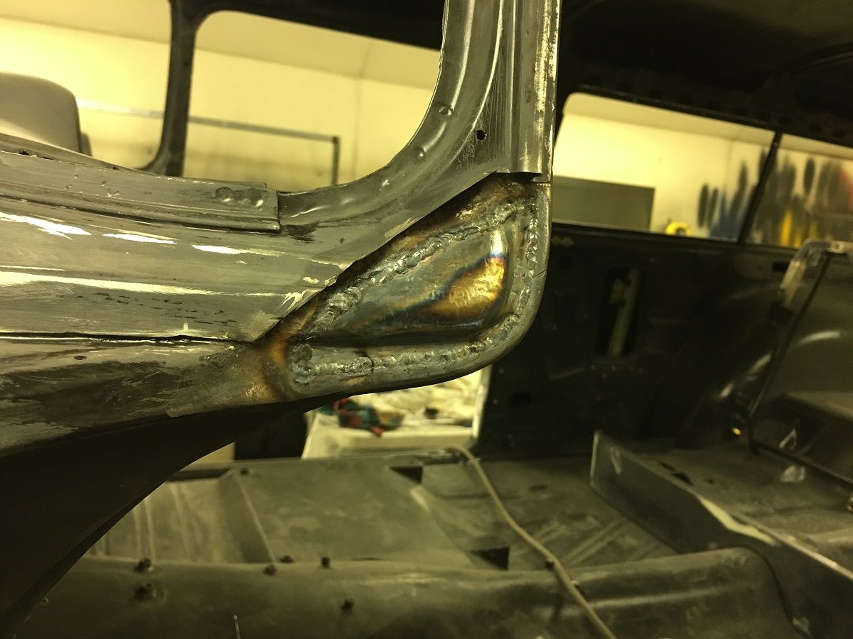
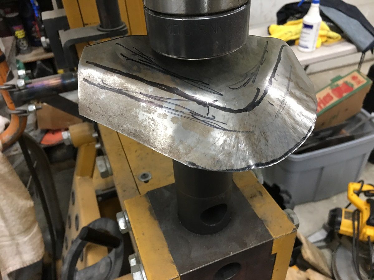
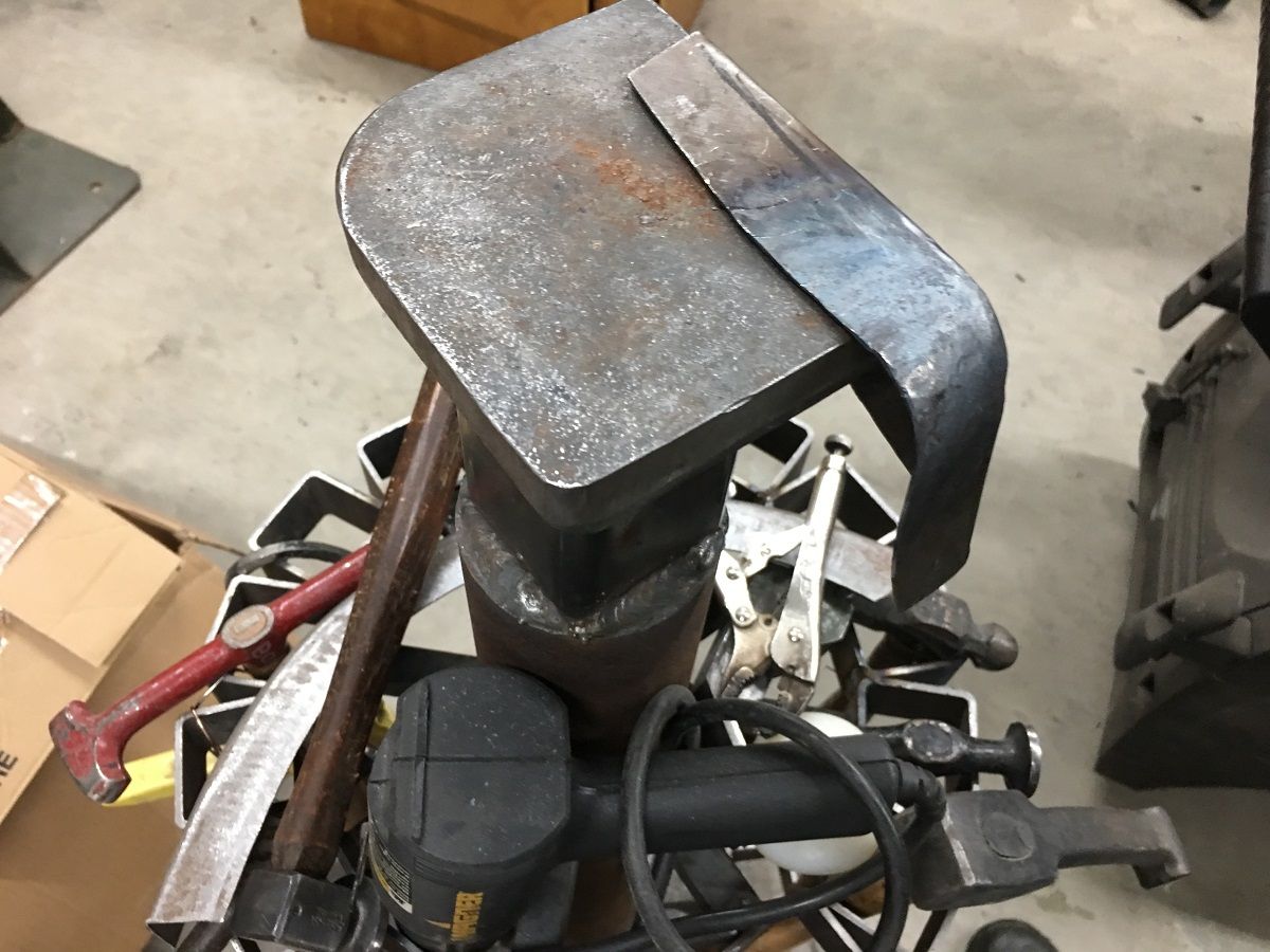
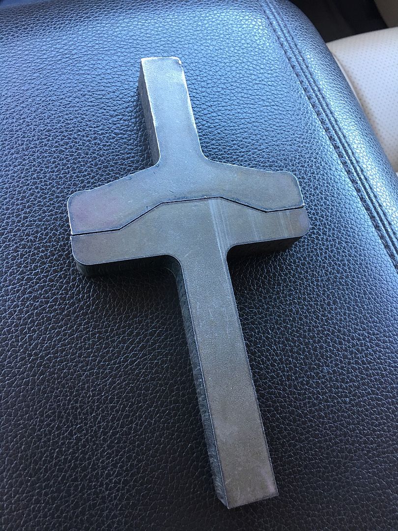
Here's some of the forming process of our A-Pillar fabrication that I missed the other day. Did a couple time lapse videos, first shows the shrinking of the corner. The Vise Grip tucking tool, torch, and hammer is used to get the corner to come down about a 20* angle, then the two flanges were folded, which gives us one big tuck. At that point wide VEE is heated up and the high spots of the flange corner is hammered back into itself. Repeat for the next high spot, until the corner is folded where you want it.
Here's the corner shrink complete...
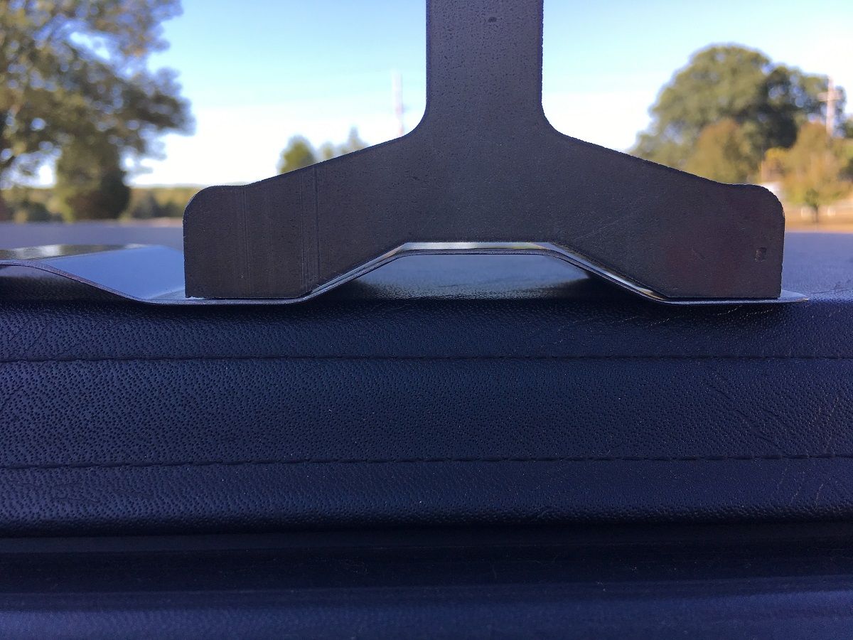
Then the barrel end hammer is used to make the joggle creases by using an upper die from our press brake as a post dolly. That’s the basic process.
If you find the time lapse too fast, you can change playback speed on YouTube to slow things down a bit..
.
.
Here's the corner shrink complete...
Then the barrel end hammer is used to make the joggle creases by using an upper die from our press brake as a post dolly. That’s the basic process.
If you find the time lapse too fast, you can change playback speed on YouTube to slow things down a bit..
.
.
Bopbop
Well-known member
Great work as always. I always keep up with this page to see if I can learn anything new.
John
John
Great work as always. I always keep up with this page to see if I can learn anything new.
John
What he said. Thanks Robert

RADcustom
Well-known member
Are you making a truck bed?
west wind
Well-known member
thanks!
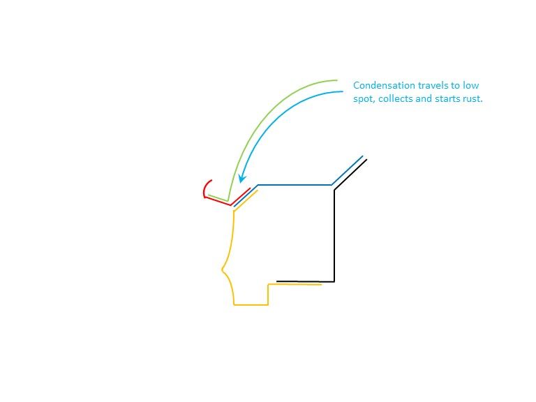
Today we worked on some rust prevention up inside the roof. This is between the roof skin and the perimeter structure just above the windows.
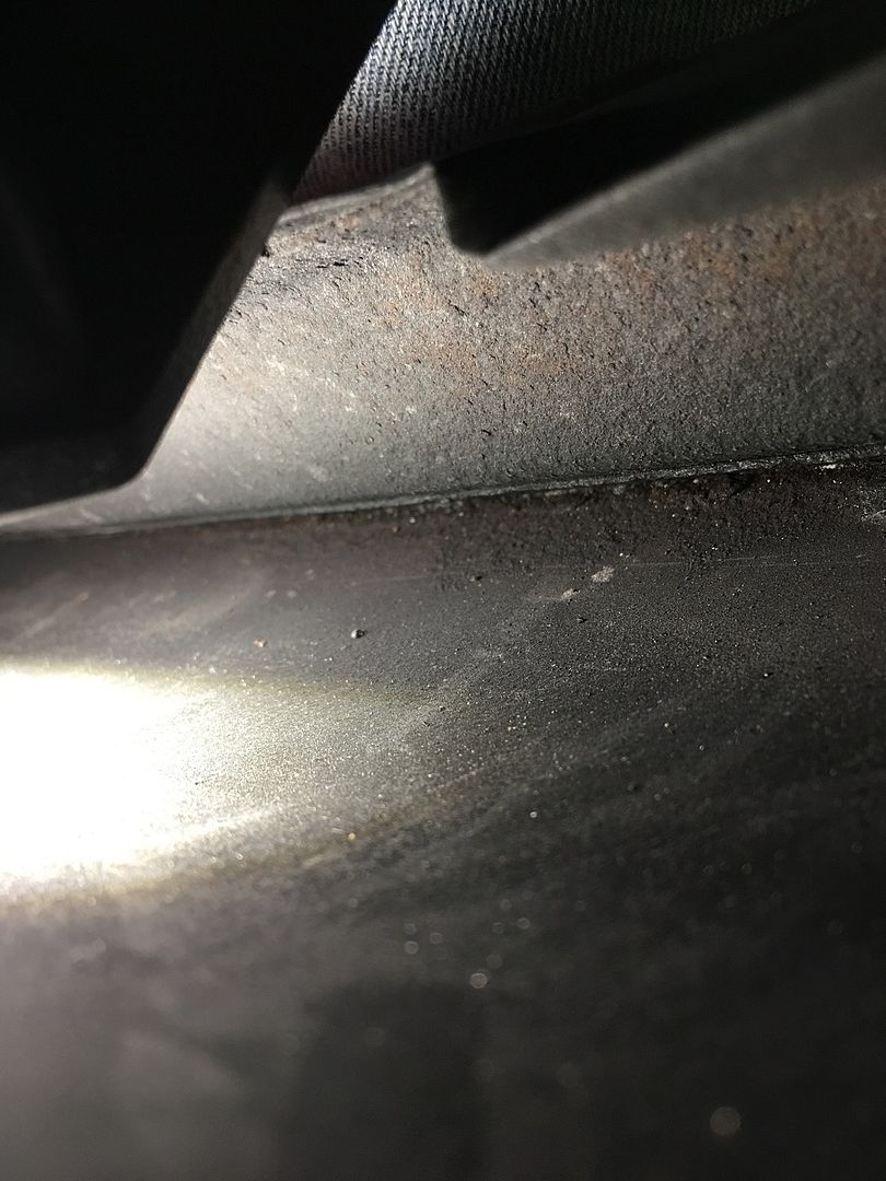
The car was rolled on it's side and SPI epoxy poured into the area, acid brush was used to cover everything we could..
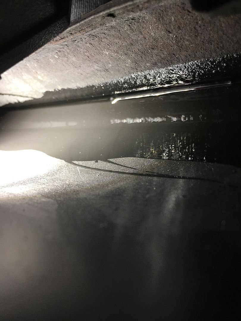
Once the entire passenger side had been flooded around to the liftgate hinge, we rolled the car right side up again. It wasn't long that we had paint dripping on the top of the rocker panel.. It was running down inside the A Pillar and running out the bottom of the dogleg. This is a good indicator of exactly where the roof condensation runs to when it reaches the A Pillar, and why we had rust issues there.
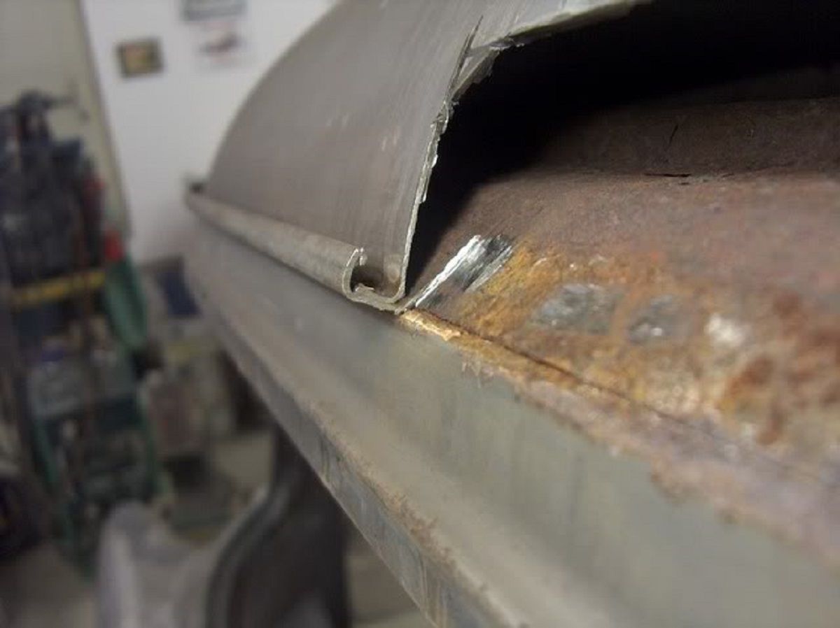
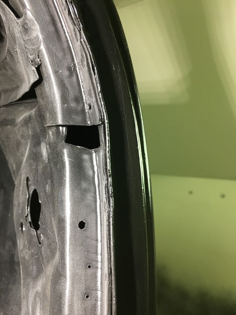
Here's a picture of when we opened the roof for rust repair, showing what the condensation did for us..
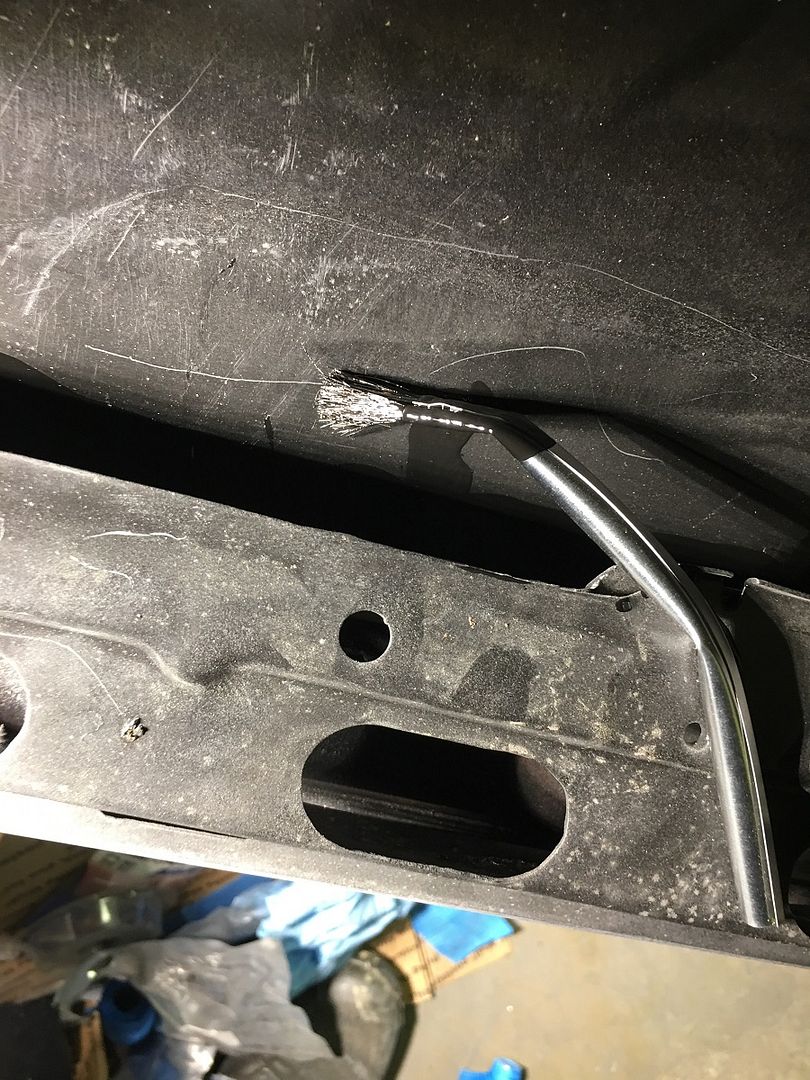
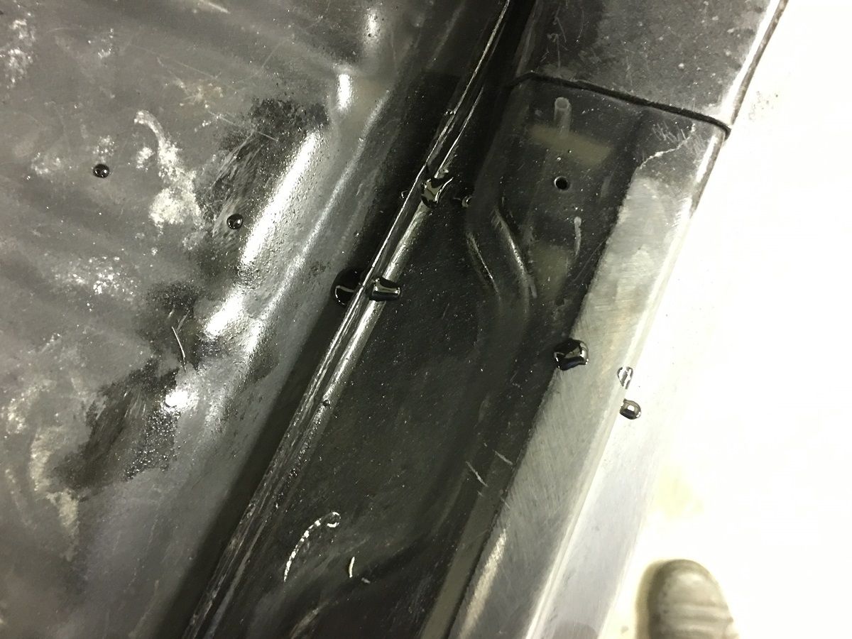
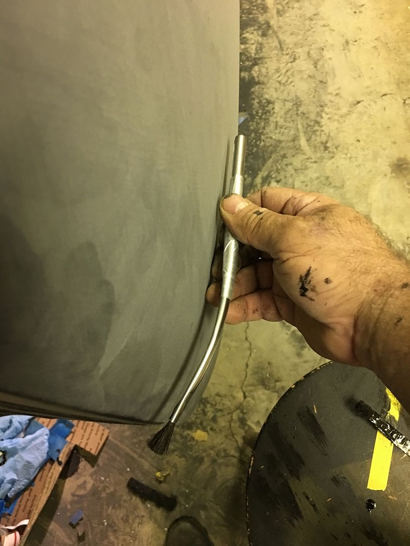
So our primer is sealing the joint between the roof skin and the structure.. We found an opening above the windshield that would help us to flood the front seam....
We opened up an acid brush to form a funnel, and poured SPI Epoxy in the area..
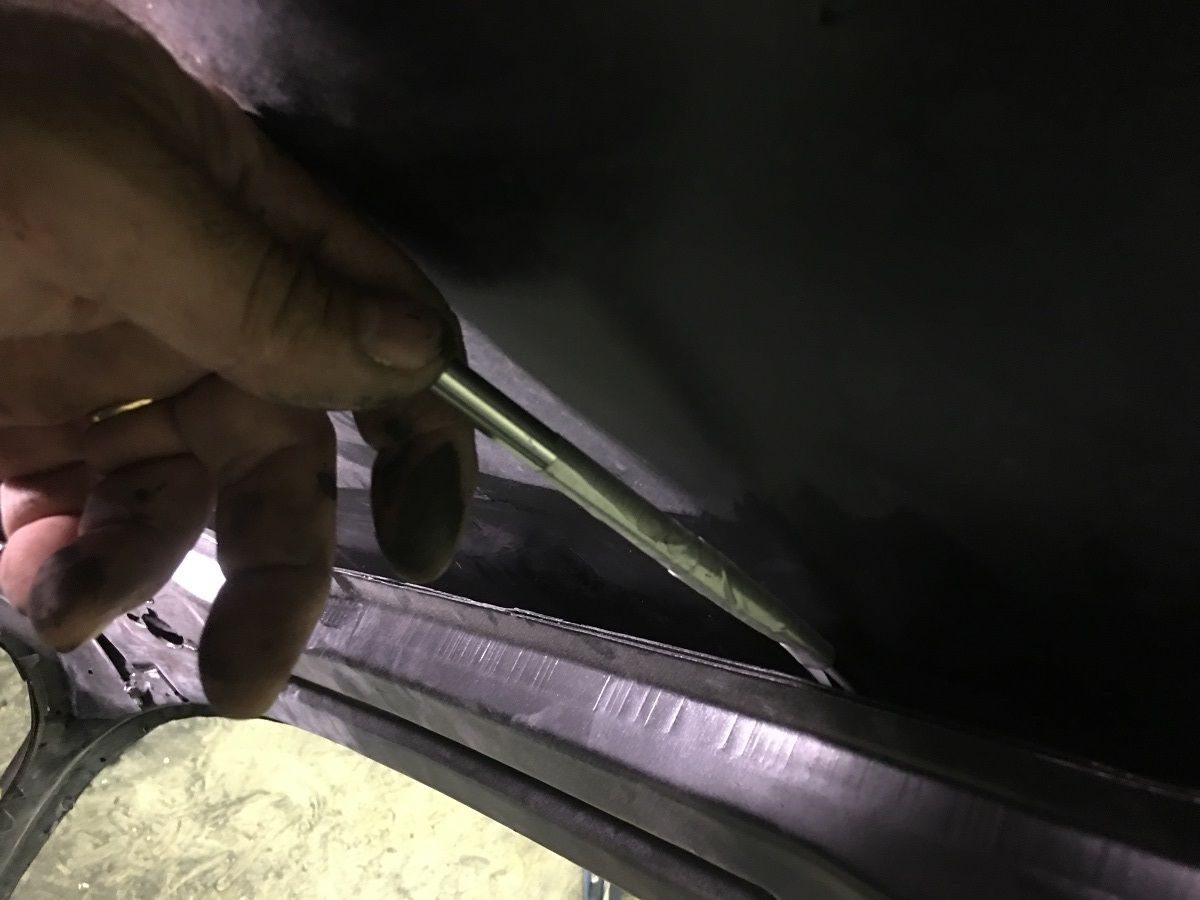
A puddle out of the A Pillar dogleg shows we have good flow through the windshield...
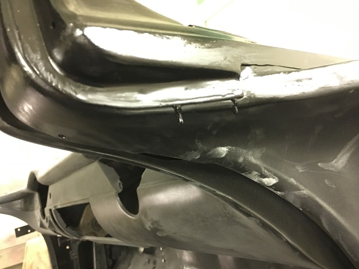
To insure everything was covered above the windshield header, we joined two acid brushes for an extended reach over the header, and bent to match the roof skin profile....
Today we worked on some rust prevention up inside the roof. This is between the roof skin and the perimeter structure just above the windows.
The car was rolled on it's side and SPI epoxy poured into the area, acid brush was used to cover everything we could..
Once the entire passenger side had been flooded around to the liftgate hinge, we rolled the car right side up again. It wasn't long that we had paint dripping on the top of the rocker panel.. It was running down inside the A Pillar and running out the bottom of the dogleg. This is a good indicator of exactly where the roof condensation runs to when it reaches the A Pillar, and why we had rust issues there.
Here's a picture of when we opened the roof for rust repair, showing what the condensation did for us..
So our primer is sealing the joint between the roof skin and the structure.. We found an opening above the windshield that would help us to flood the front seam....
We opened up an acid brush to form a funnel, and poured SPI Epoxy in the area..
A puddle out of the A Pillar dogleg shows we have good flow through the windshield...
To insure everything was covered above the windshield header, we joined two acid brushes for an extended reach over the header, and bent to match the roof skin profile....
WoodsTruck
Well-known member
- Joined
- Jan 12, 2013
- Messages
- 1,029

RADcustom
Well-known member
I'm not sure OSHA would approve of your step stool.
Last edited:
I love your attention to the unseen.
Would using something like a clean zoom-spout bottle and tube help place the SPI sealer in hard to reach places that the brush could then distribute?
This is one of those do whatever gets the job done. If I had one of those here I probably would have tried it.
I'm not sure OSHA would approve of your step stool.
C’mon, it has a built in safety railing and everything!
67CarGuy
Well-known member
I wish this thread would go on forever. Lots of great stuff to learn.
I'm just getting here, so for me it is! Robert, it's great that you're willing to share so much of your talents with us. I might just have to take a drive down to your neck of the woods this fall/winter... I've got a project that could use your skills!

I'm just getting here, so for me it is! Robert, it's great that you're willing to share so much of your talents with us. I might just have to take a drive down to your neck of the woods this fall/winter... I've got a project that could use your skills!
I'm about a two hour drive from Baltimore, so shoot me a message if you're up for a visit..
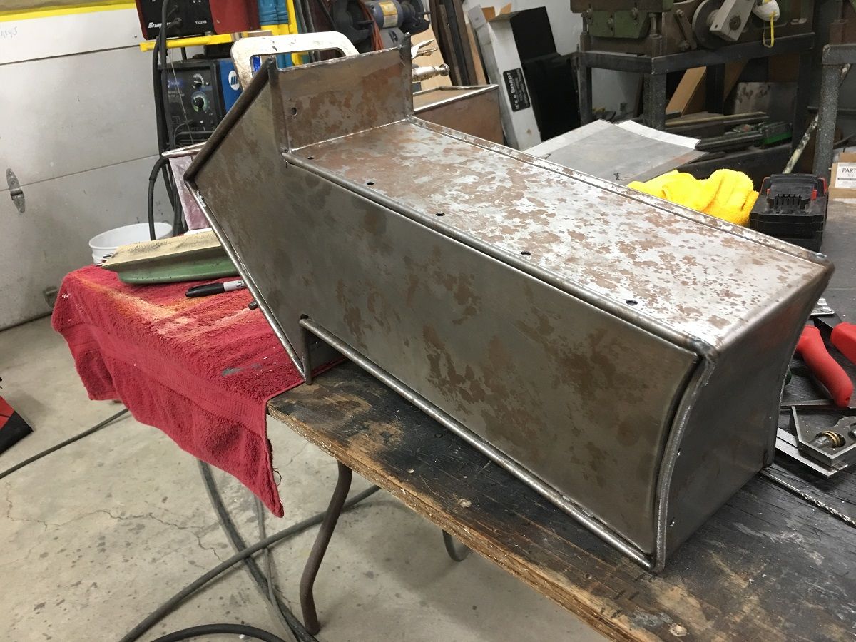
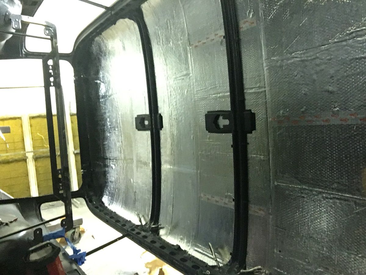
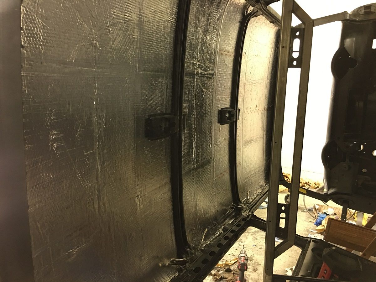
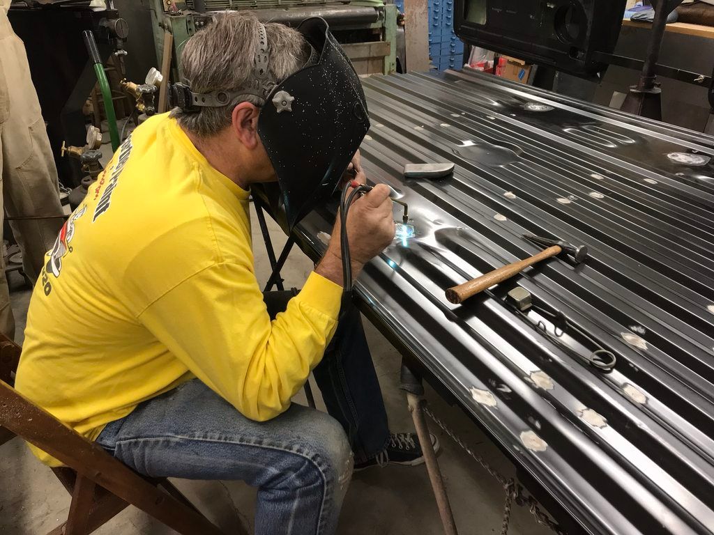
Progress this weekend, We had originally left the factory jute insulation under the roof supports, thinking we could just **** up to it with the new stuff. After installing the Noico inside the doors, I guess my OCD wasn't about to leave the old stuff in the roof. So the bottom edge of the roof supports were scribed on the driver's side for relocation purposes, de-spot welded, and pulled downward enough to scrape off the old jute..
The bare area is then scuffed with 80 grit and two coats of SPI epoxy primer applied.. After that sets up we applied the Noico sound deadening mat to the inside of the roof skin. Then the roof supports are aligned with our scribed marks and plug welded in place..
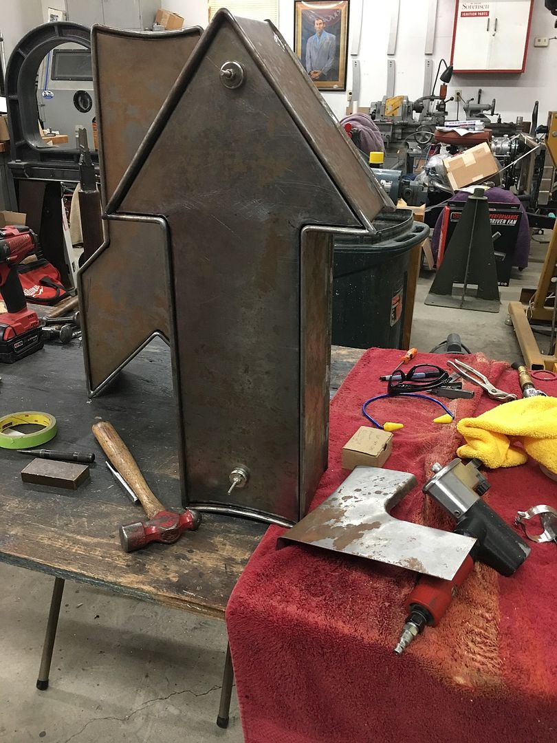
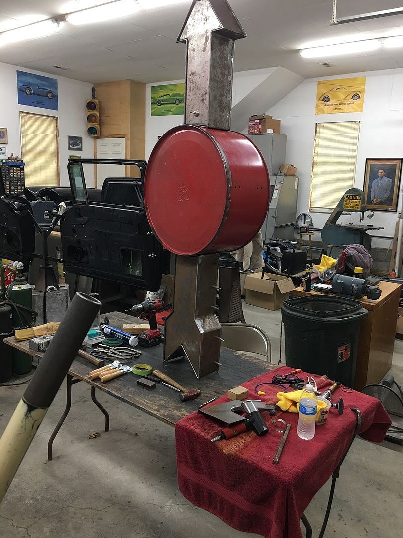
Mike has been plugging along on the Drummers Lounge sign, the arrow is close to done, it still needs fastening hardware added for the access panels, and holes added for the lights..
The bare area is then scuffed with 80 grit and two coats of SPI epoxy primer applied.. After that sets up we applied the Noico sound deadening mat to the inside of the roof skin. Then the roof supports are aligned with our scribed marks and plug welded in place..
Mike has been plugging along on the Drummers Lounge sign, the arrow is close to done, it still needs fastening hardware added for the access panels, and holes added for the lights..
Last edited:
TimeWarpF100
Well-known member
Awesome as usual, read every post but not much to say that's not already been said.
Where is the car originally from?
Where is the car originally from?
larry4406
Well-known member
The struggle is real. Today’s “you can never have enough clamps” purchase to feed the addiction.

Nice haul!
C91x
Well-known member
The struggle is real. Today’s “you can never have enough clamps” purchase to feed the addiction.
Not sure if it was here or on all metal shaping but i stole your tucking vice grip modification. It works awesome
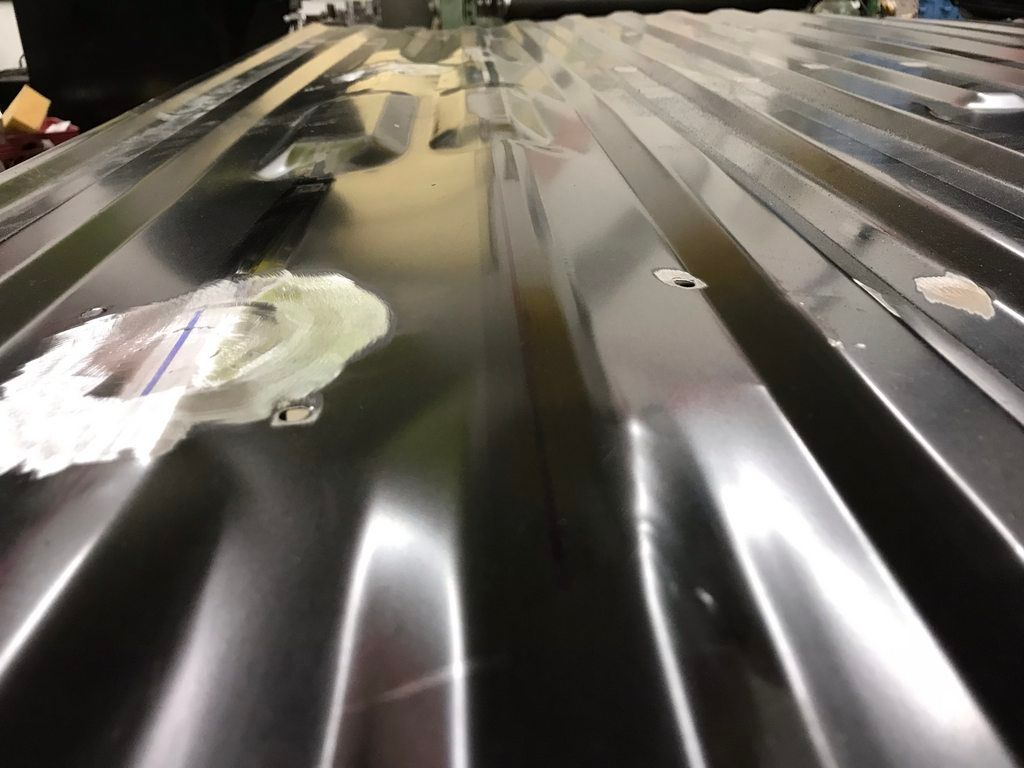
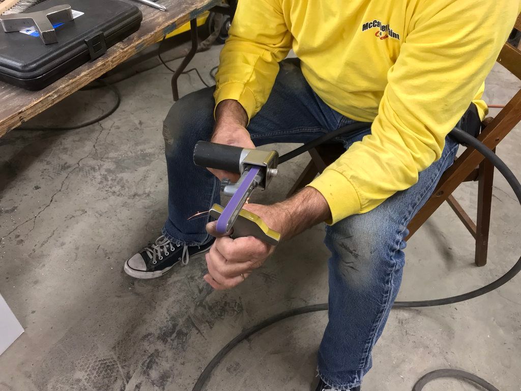
Progress doesn't look much like progress, but I'm still plugging along on the Sound Deadening mat, may need another box...

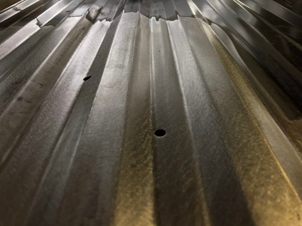
The floor has a few holes that go through, perhaps for drainage? I'm not too keen on the plastic or metal push in plugs, as I feel they will leak, so these rubber push-in panel plugs from McMaster will be used instead..


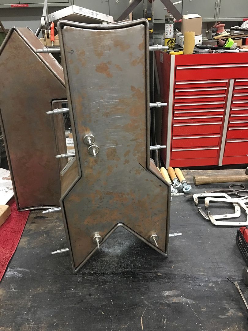
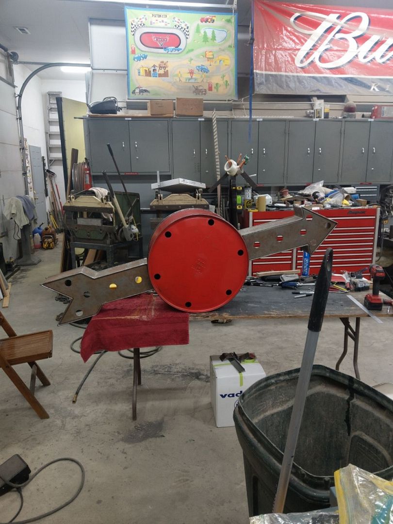
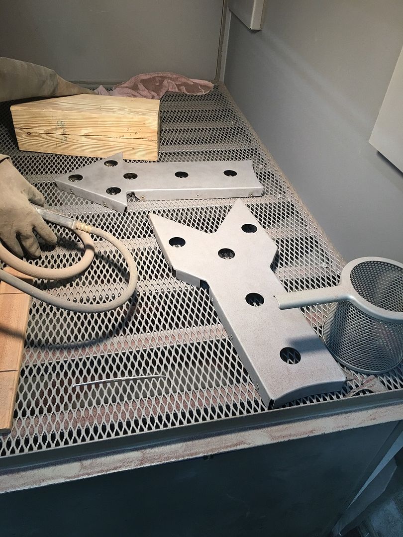
Meanwhile, Mike continues on the Drummer's Lounge sign, all the light holes are in place and he is media blasting...….
The floor has a few holes that go through, perhaps for drainage? I'm not too keen on the plastic or metal push in plugs, as I feel they will leak, so these rubber push-in panel plugs from McMaster will be used instead..
Meanwhile, Mike continues on the Drummer's Lounge sign, all the light holes are in place and he is media blasting...….
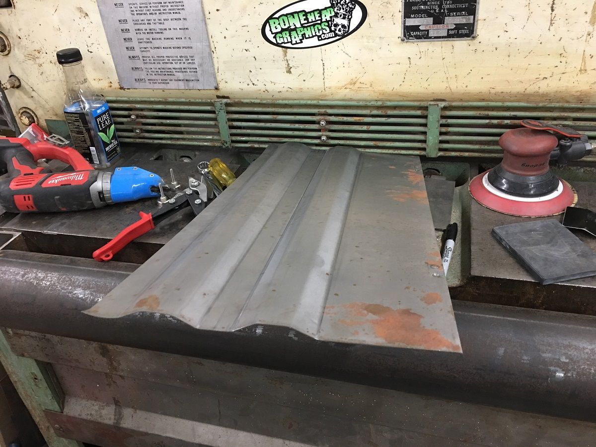
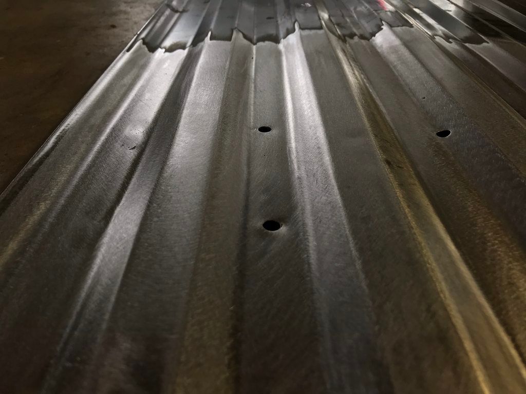
Had some visitors at the shop this week, John Glenn and his father (from Anderson Auto Glass, Anderson SC) came up so we could use the truck floor dies to modify the ribs on a 2009 Ford replacement floor for use in a 1966 Ford they are restoring. The new floor has flat area provisions for a fifth wheel bracket and the original floor in a 1966 has full length ribs front to rear. We needed to modify the flat areas to provide these full length ribs. James McKenzie also stopped by to help in the activites.
QUOTE (John Glenn) I didn't go into much detail about this earlier, but the F250 bed floor had four flat areas for a fifth wheel hitch that looked really out of place for use in a '66 F100. I contacted Robert (MP&C) about having him make dies for his Lennox to reshape those spots into continuous ribs to look more like the original bed floor. I sent a sample so he could make dies a while back, and yesterday our schedules finally aligned so we could work on the bed floor.
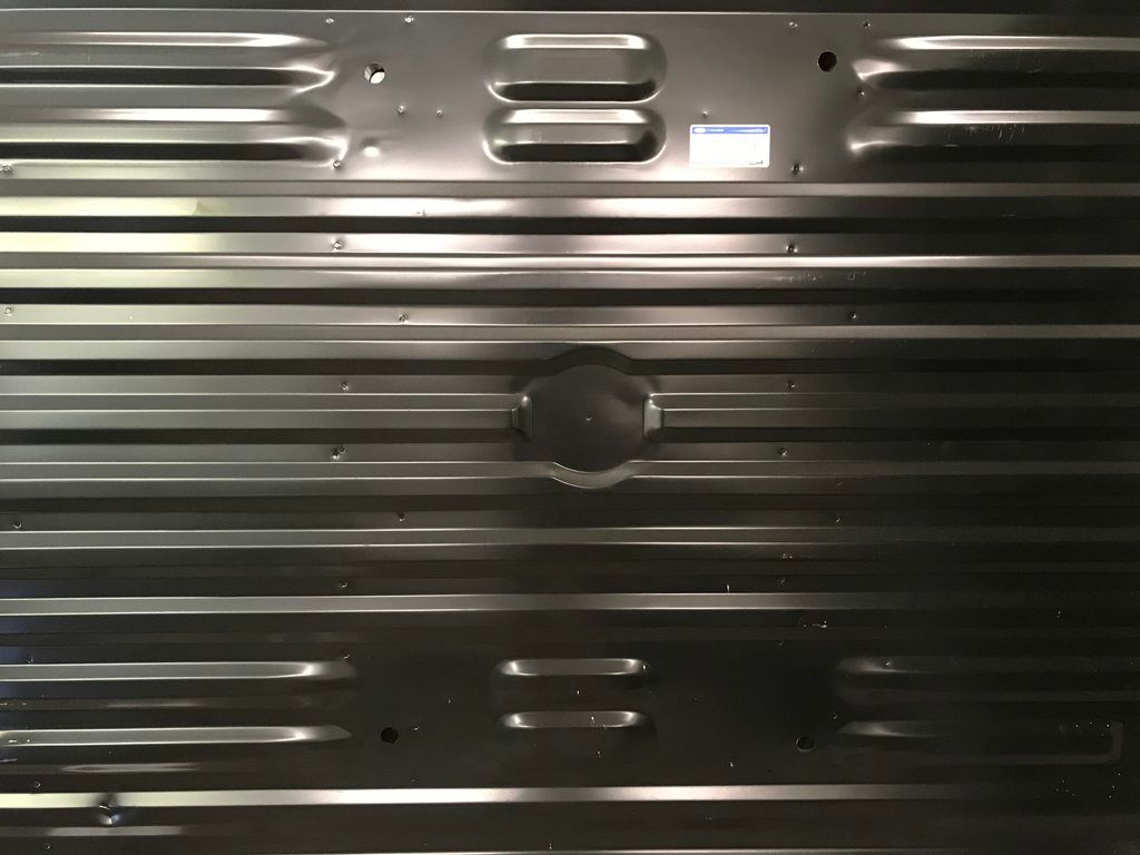
We started by gas welding plugs in the four holes that won't be used on the F100. I didn't want to weld those with a MIG at our shop since the weld would be more brittle and would probably crack during the reshaping process. Gas welds are much softer and more workable.
The welds were smoothed down and the flat areas were pre-stretched in the english wheel with a bit of guesswork as to how much we should pre-stretch.
Then into the Lennox to add the ribs. This was done gradually in multiple passes, adjusting the depth of the dies after each pass.
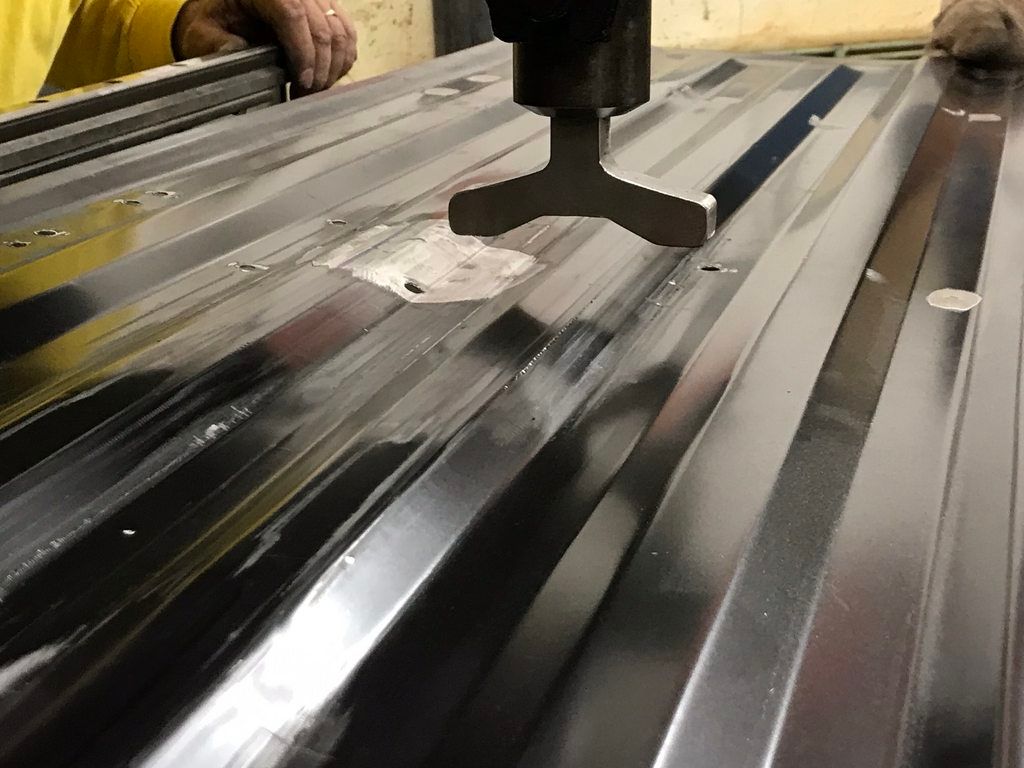
Slightly reworking the dies to gain more rib height.
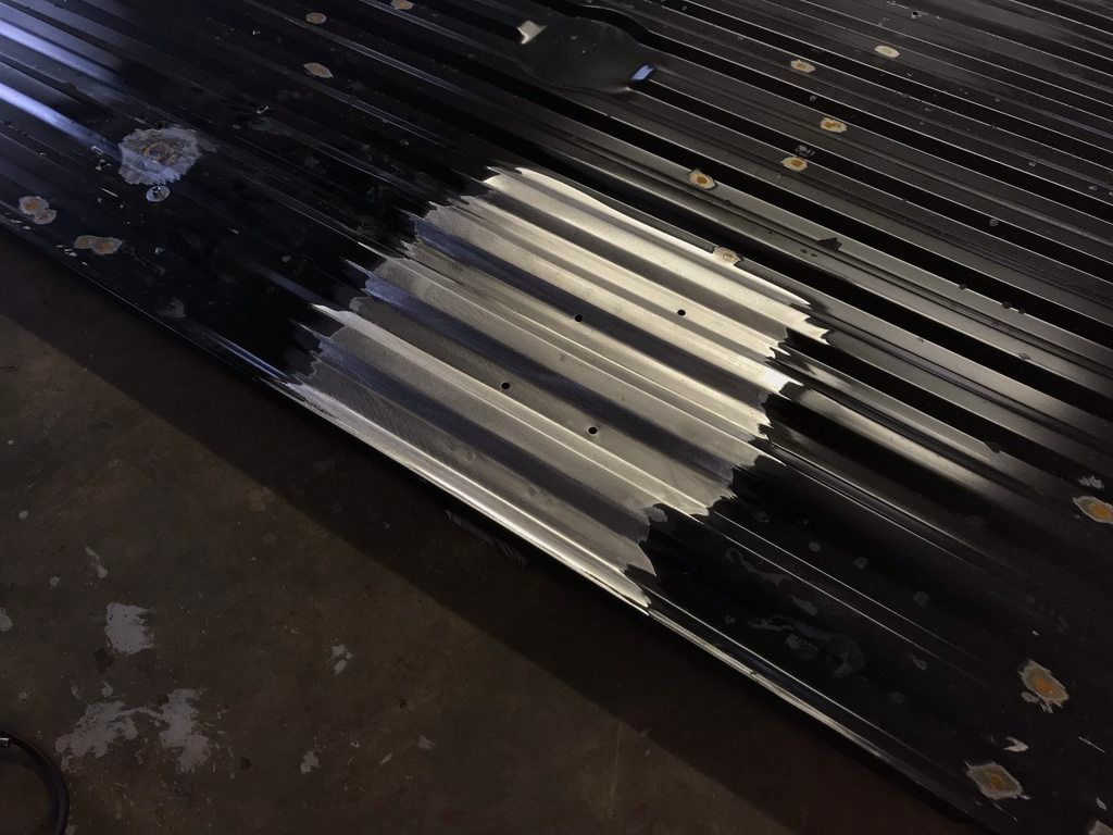
Finished ribs. These are hard to photograph so I stripped an area with the two new ribs in the center of the outer original ribs to show the matching profile.
James (duallyjams) dropped in to hang out for the day, it's always good seeing him! He was a big help and also shot vids of us working.
Time lapse:
Shaping Full Length Bed Floor Ribs- ?66 F100 - YouTube
QUOTE (John Glenn) I didn't go into much detail about this earlier, but the F250 bed floor had four flat areas for a fifth wheel hitch that looked really out of place for use in a '66 F100. I contacted Robert (MP&C) about having him make dies for his Lennox to reshape those spots into continuous ribs to look more like the original bed floor. I sent a sample so he could make dies a while back, and yesterday our schedules finally aligned so we could work on the bed floor.
We started by gas welding plugs in the four holes that won't be used on the F100. I didn't want to weld those with a MIG at our shop since the weld would be more brittle and would probably crack during the reshaping process. Gas welds are much softer and more workable.
The welds were smoothed down and the flat areas were pre-stretched in the english wheel with a bit of guesswork as to how much we should pre-stretch.
Then into the Lennox to add the ribs. This was done gradually in multiple passes, adjusting the depth of the dies after each pass.
Slightly reworking the dies to gain more rib height.
Finished ribs. These are hard to photograph so I stripped an area with the two new ribs in the center of the outer original ribs to show the matching profile.
James (duallyjams) dropped in to hang out for the day, it's always good seeing him! He was a big help and also shot vids of us working.
Time lapse:
Shaping Full Length Bed Floor Ribs- ?66 F100 - YouTube
Last edited:
strokershovel
Member
- Joined
- Feb 28, 2017
- Messages
- 5
Hello, I'm not trying to hijack this thread, If I should post somewhere else please let me know.
I have been following MP&C shop projects for quite some time now and have really learned alot! I'm about to install a steel hood scoop on my 1976 Buick Skylark and I am looking for the proper way to weld it to the hood. I know that **** welding it would be the proper way but the scoop is 2' wide and 53" long. I don't want to open up a hole that big in the hood for fear of no support. I only plan on a hole a little bit bigger than the air cleaner. What would be the correct way to install it?
Thanks, Keith
Keith, does the bottom of the scoop have the same crown profile as the hood? If the scoop is flat, you’ll be hard pressed to get that to lay on there right without introducing
all sorts of distortion. If the hood scoop has the same crown on the bottom edge as the crown of the hood skin, then you have a fighting chance.
all sorts of distortion. If the hood scoop has the same crown on the bottom edge as the crown of the hood skin, then you have a fighting chance.
racer-john
Well-known member
@Robert The pics on page 3236 do not show as they "contain errors".
Very nice work on the "wagon" as usual.
Very nice work on the "wagon" as usual.