You are using an out of date browser. It may not display this or other websites correctly.
You should upgrade or use an alternative browser.
You should upgrade or use an alternative browser.
MP&C Shop Projects
- Thread starter MP&C
- Start date

stinkity stoink
Well-known member
Great work Robert !!!
strokershovel
Member
- Joined
- Feb 28, 2017
- Messages
- 5
Keith, does the bottom of the scoop have the same crown profile as the hood? If the scoop is flat, you’ll be hard pressed to get that to lay on there right without introducing
all sorts of distortion. If the hood scoop has the same crown on the bottom edge as the crown of the hood skin, then you have a fighting chance.
Thanks for the quick reply Robert! The scoop has a crown down the center and pretty flat along the bottom edge but the hood is fairly flat too. I will get pics of both the hood and scoop today and post.
Thanks! Keith
strokershovel
Member
- Joined
- Feb 28, 2017
- Messages
- 5


 Here are some pics, there is a bit of a gap at the front
Here are some pics, there is a bit of a gap at the front
The hood flange does not match the hood (the front gap) and you'll never get it to lay right if you try using that flange. What I see as your options:
-Move the scoop rearward until the flange lays down on the hood and cut off the excess overhang in the rear. If the hood has an upsweep at the cowl area, you may need to slice the hood scoop just above the flange in that area, move to match the hood profile, and reweld. Hood to scoop weld seam is on the flat of the hood skin.
-Cut the flange off the hood scoop. Leave excess material on the hood skin when you go to cut the hole, and roll the edge upward to meet up with the hood sides. This method will require a grunch of stretching in the corners to keep the transition in one piece. Hood to scoop weld seam is on the side of the hood scoop. If you can manage all the tipping and stretching with consistency, this method would result in less weld distortion based on weld placement. If you feel this is a bit out of your skillset, I could likely point you to a metalshaper local to your area to help out with the project.
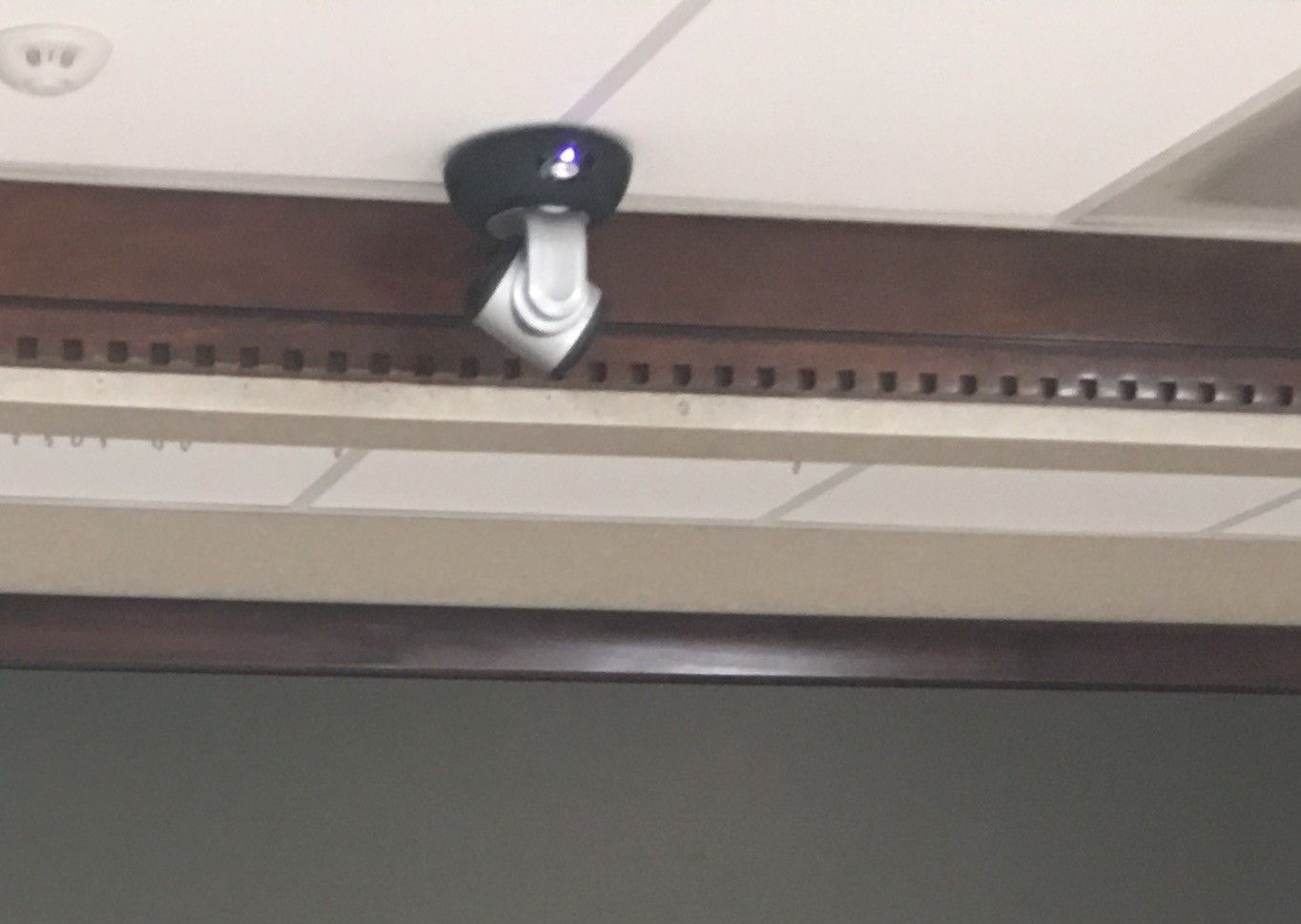
A fabrication I did recently for the day job. We had a requirement for a PTZ camera to be ceiling mounted, and the ceiling grid was dead center of the room, and dead center of the video wall. Normally these cameras have a mounting solution that puts them in a ceiling tile, but that conflicts with my OCD to center the camera with everything else. This particular camera has a single threaded hole in the bottom center (top center if mounted upside down). One of my co-workers suggested you could not mount it centered on the ceiling grid given the mounting hole location.
Challenge accepted (hold my beer moment). Used 16 GA stainless sheet, bent to conform to the grid so the ceiling tiles would remain intact without notches. The two halves are held together just above the grid using 1/4-20 bolts and lock nuts, the upper angled "wings" have holes for safety wire supports to insure we're in compliance.

Video version:

Video version:
Installed:
Challenge accepted (hold my beer moment). Used 16 GA stainless sheet, bent to conform to the grid so the ceiling tiles would remain intact without notches. The two halves are held together just above the grid using 1/4-20 bolts and lock nuts, the upper angled "wings" have holes for safety wire supports to insure we're in compliance.
Video version:
Video version:
Installed:
Bob Heine
ALLIANCE MEMBER
Robert, that right there is a funny story!!! Brilliant execution too.
strokershovel
Member
- Joined
- Feb 28, 2017
- Messages
- 5
The hood flange does not match the hood (the front gap) and you'll never get it to lay right if you try using that flange. What I see as your options:
-Move the scoop rearward until the flange lays down on the hood and cut off the excess overhang in the rear. If the hood has an upsweep at the cowl area, you may need to slice the hood scoop just above the flange in that area, move to match the hood profile, and reweld. Hood to scoop weld seam is on the flat of the hood skin.
-Cut the flange off the hood scoop. Leave excess material on the hood skin when you go to cut the hole, and roll the edge upward to meet up with the hood sides. This method will require a grunch of stretching in the corners to keep the transition in one piece. Hood to scoop weld seam is on the side of the hood scoop. If you can manage all the tipping and stretching with consistency, this method would result in less weld distortion based on weld placement. If you feel this is a bit out of your skillset, I could likely point you to a metalshaper local to your area to help out with the project.
I want to try moving the scoop back but I will need to remove the hood first, the windshield is in the way.
On the welding to the hood, would it be spot or stitch weld. I will be using a 120v wire feed welder with .025 wire.
Thanks, Keith
This post explains the "dot weld" method fairly well...
https://www.garagejournal.com/forum/showpost.php?p=4431232&postcount=388
…...and if you have time, review the entire thread from page one to the end.. the MIG process is the primary focus of the thread.
https://www.garagejournal.com/forum/showpost.php?p=4431232&postcount=388
…...and if you have time, review the entire thread from page one to the end.. the MIG process is the primary focus of the thread.
strokershovel
Member
- Joined
- Feb 28, 2017
- Messages
- 5
…...and if you have time, review the entire thread from page one to the end.. the MIG process is the primary focus of the thread.[/QUOTE]
Thank you, I will do that.
Keith
Thank you, I will do that.
Keith
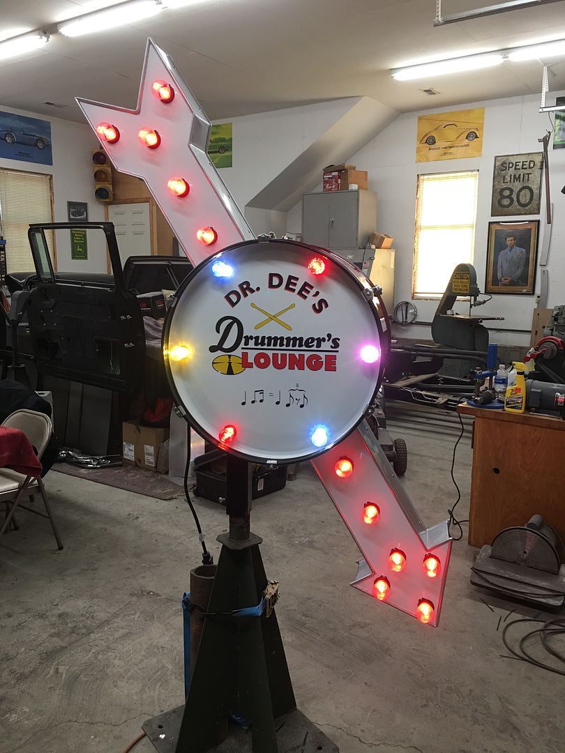
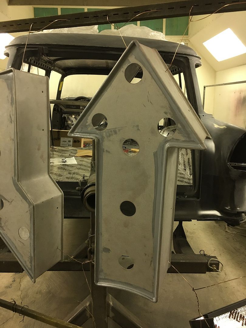
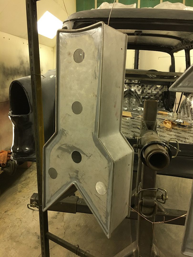
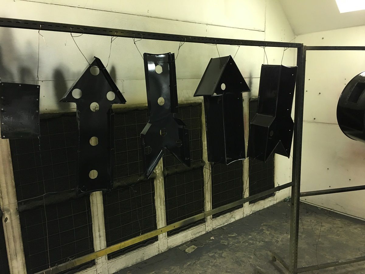
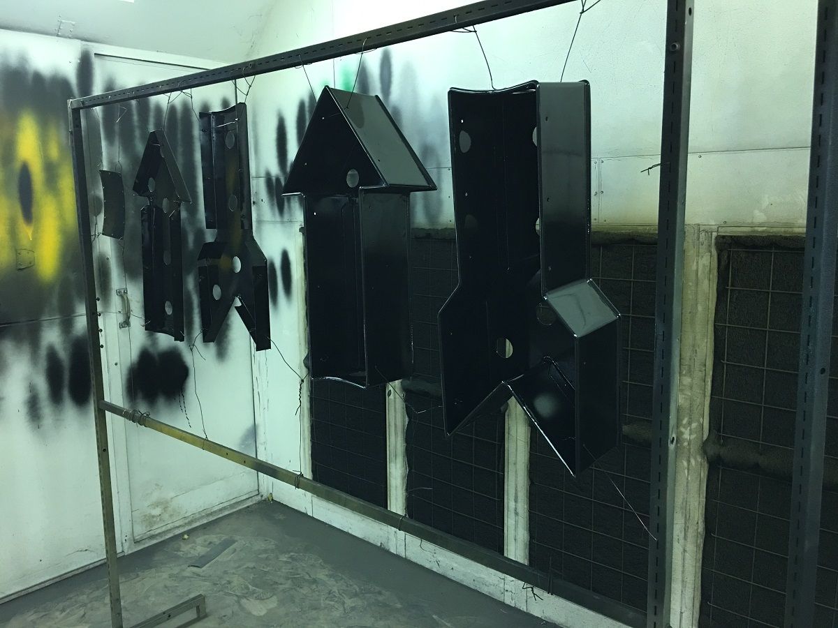
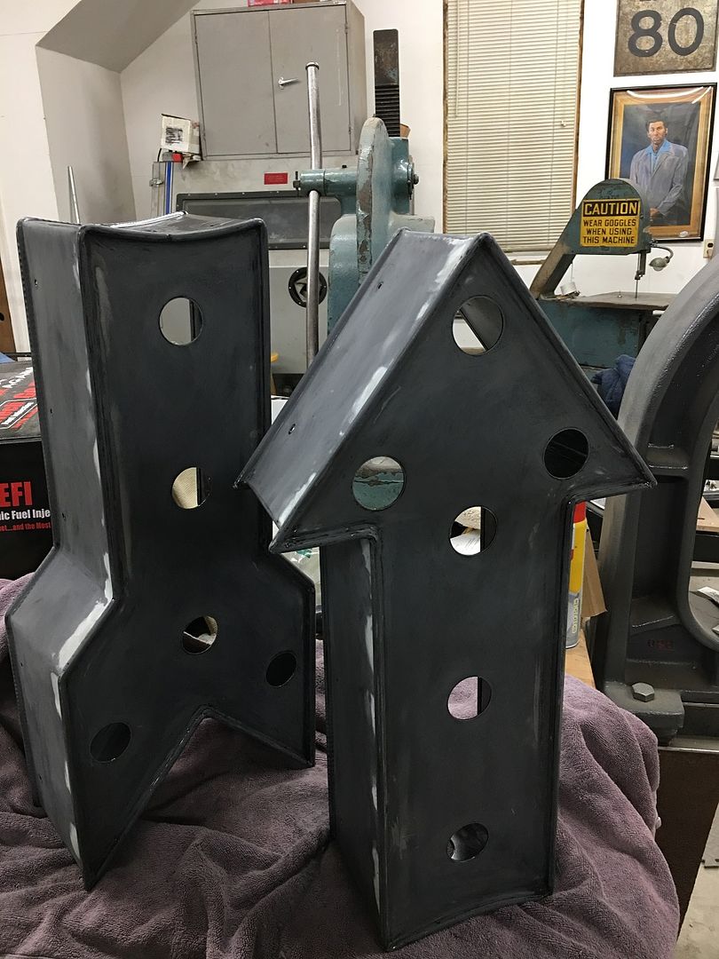
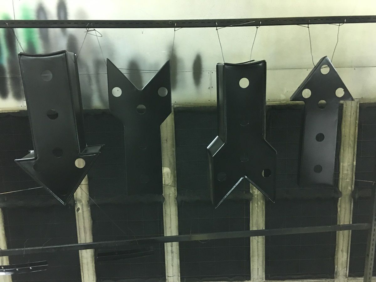
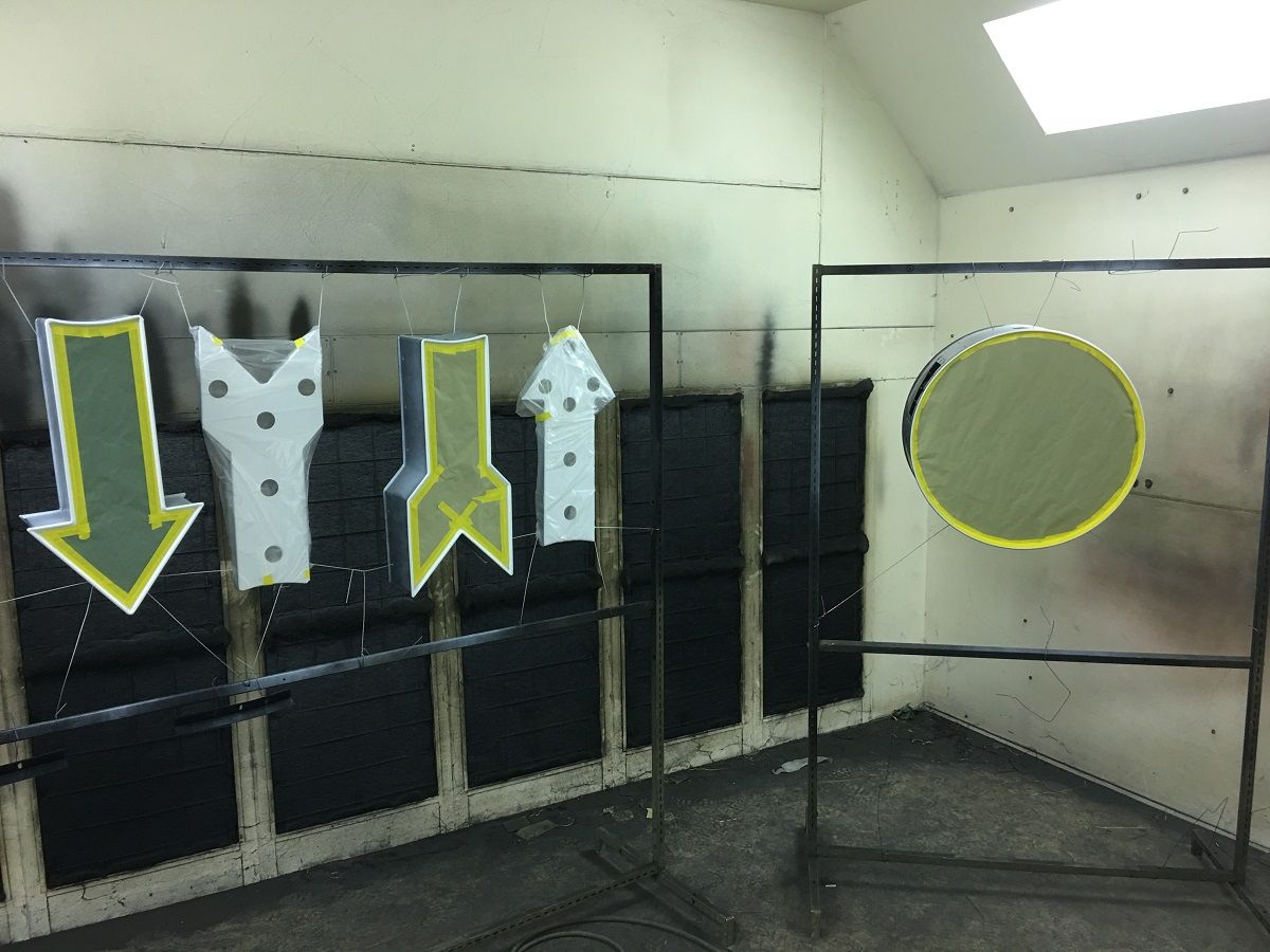
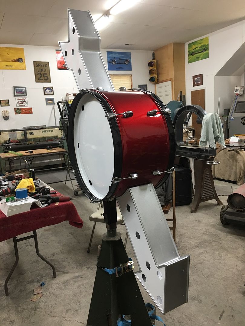
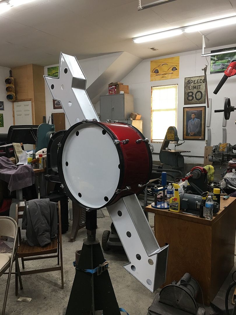
Mike has been plugging along on the Drummer's lounge sign, today he got all the parts prepped, hung up, and epoxy primed..
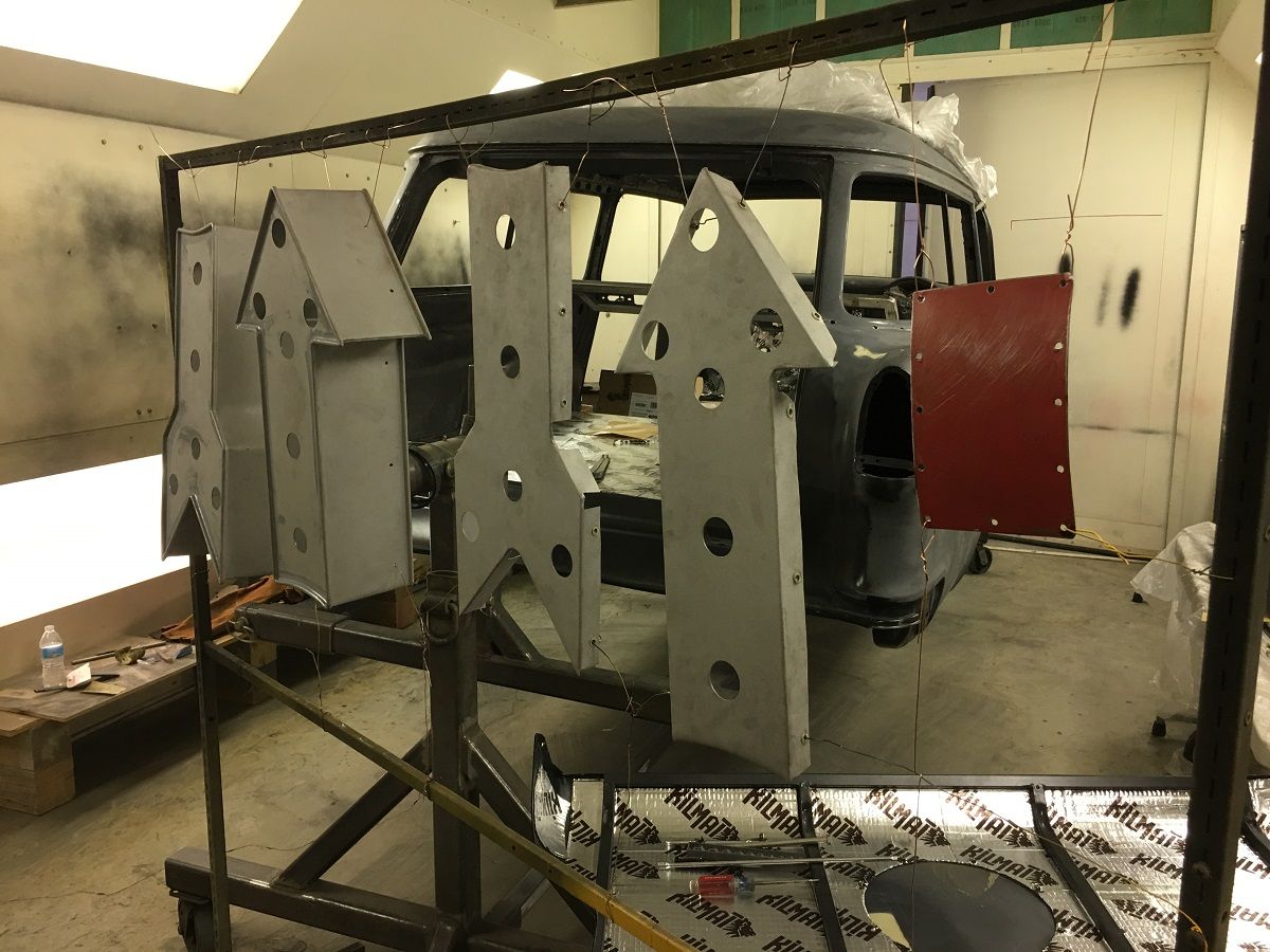
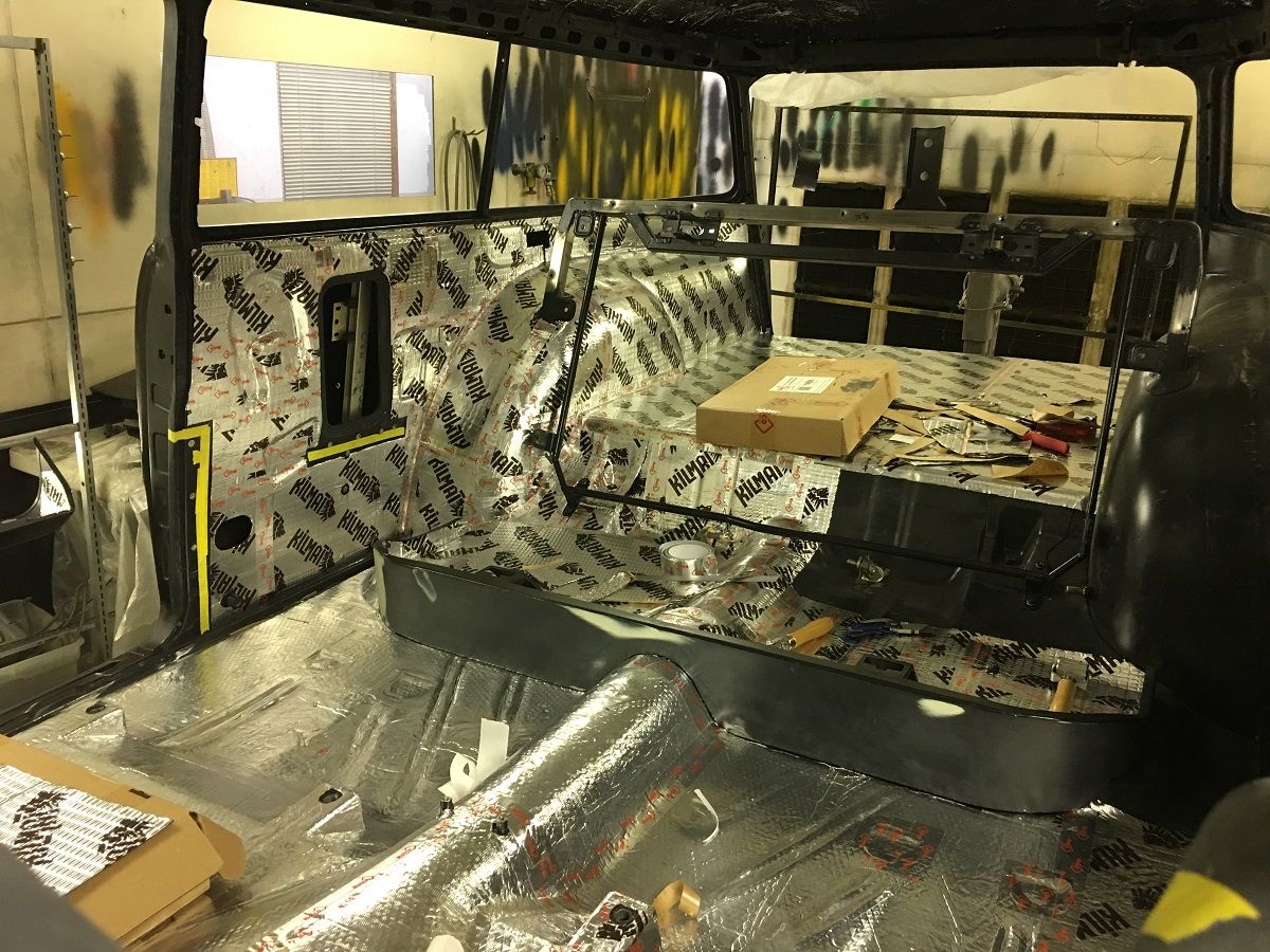
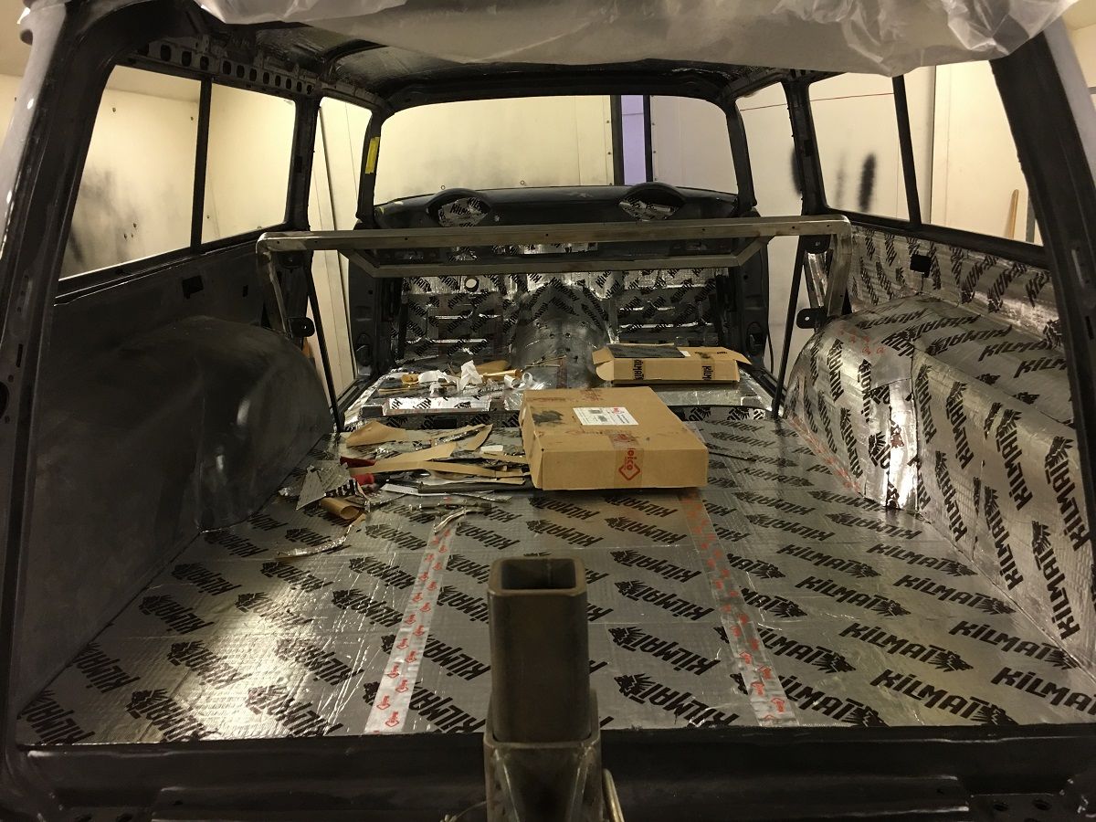
I'm still installing sound deadener, gone through 4 boxes and have another one coming this week. We also added some wall decoration, a vintage speed limit sign. Used to read 30, but we added some black paint and the sign had enough dirt on it to "blend" in the paint once it was tacky...
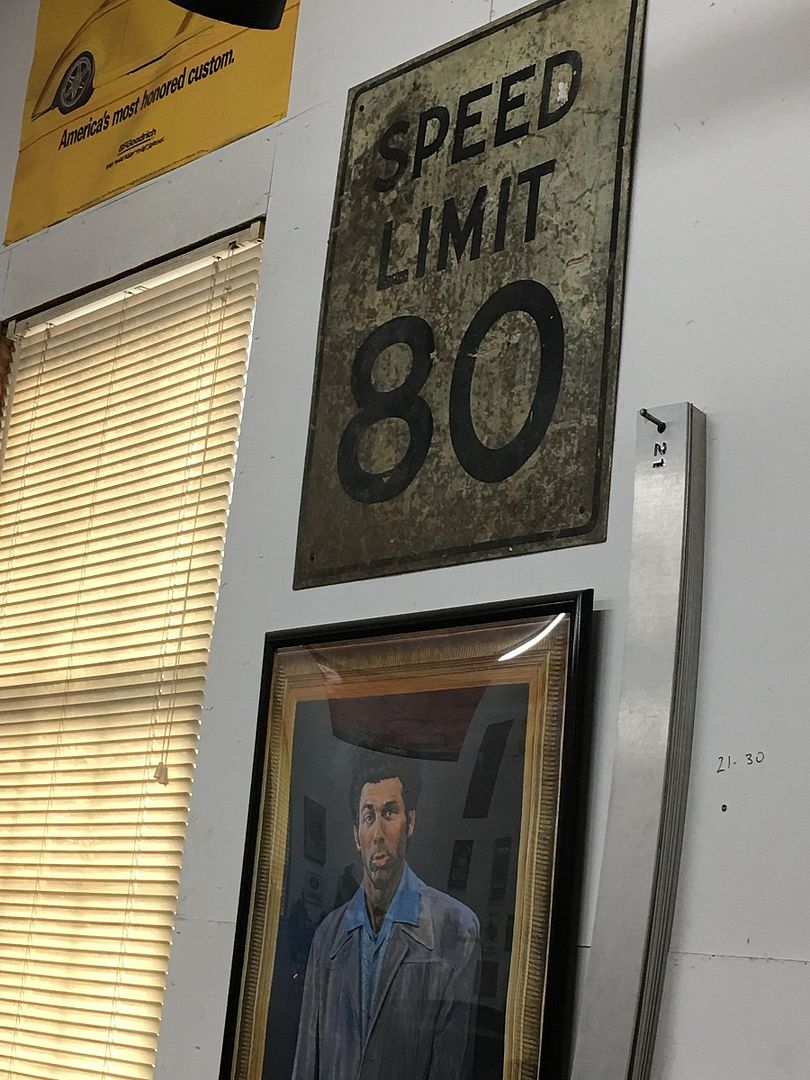
I'm still installing sound deadener, gone through 4 boxes and have another one coming this week. We also added some wall decoration, a vintage speed limit sign. Used to read 30, but we added some black paint and the sign had enough dirt on it to "blend" in the paint once it was tacky...
xtremek
Well-known member
Looking really good. Gotta ask though, what's the yellow tape for?
BORING HOP YARD
Well-known member
Nice work Robert!
Are you seeing any light at the end of the tunnel, it seems from this view point your very close to pulling the trigger. Thank you for sharing!
Are you seeing any light at the end of the tunnel, it seems from this view point your very close to pulling the trigger. Thank you for sharing!
xtremek
Well-known member
Are you doing the final assembly as well? I hope so, that way we can see the final product.
xtremek
Well-known member

So there has been some discussion online of making the Lennox style machines to function more like a Pullmax (the multi-position lever settings, not the oil leaks ") ) I posted up a "sketch" of my thoughts on the subject … using a bolt-on bracket that would use existing hardware..
) I posted up a "sketch" of my thoughts on the subject … using a bolt-on bracket that would use existing hardware..
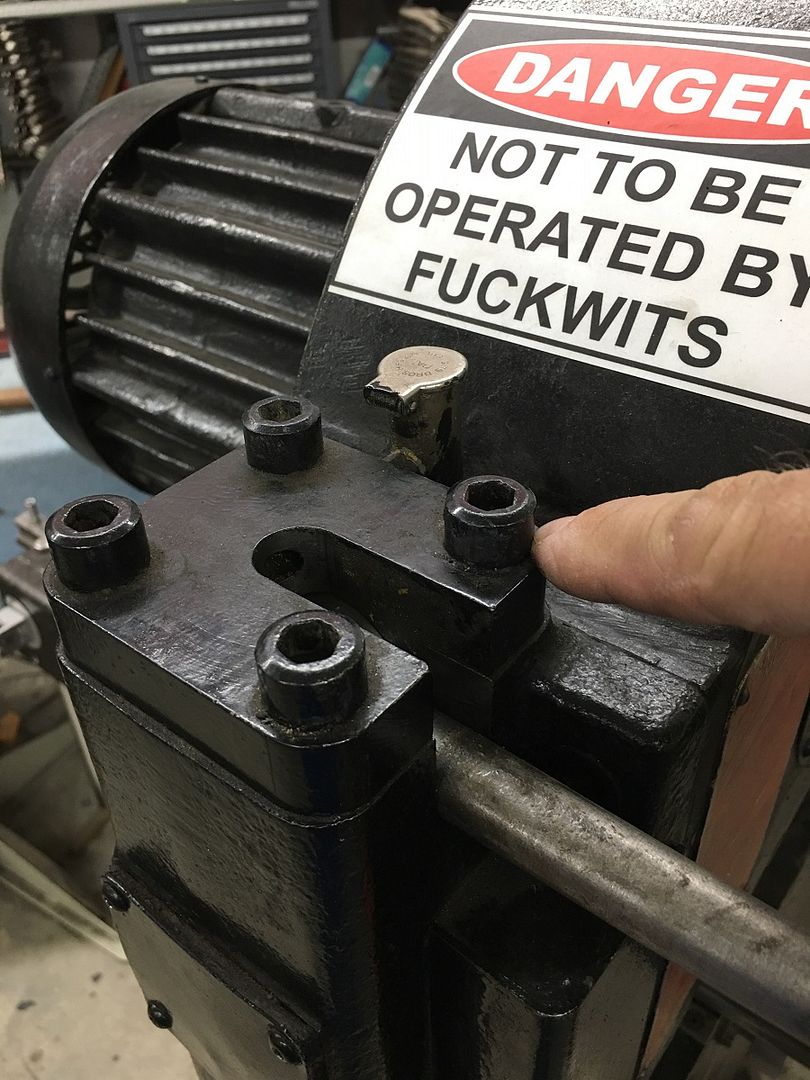
Mike Wagner (Cornfield Customs) has better capability in machinery and cutting parts, and took it from there to make a prototype bracket using the bolt on design, and a slight modification of the original actuator lever (includes welding)
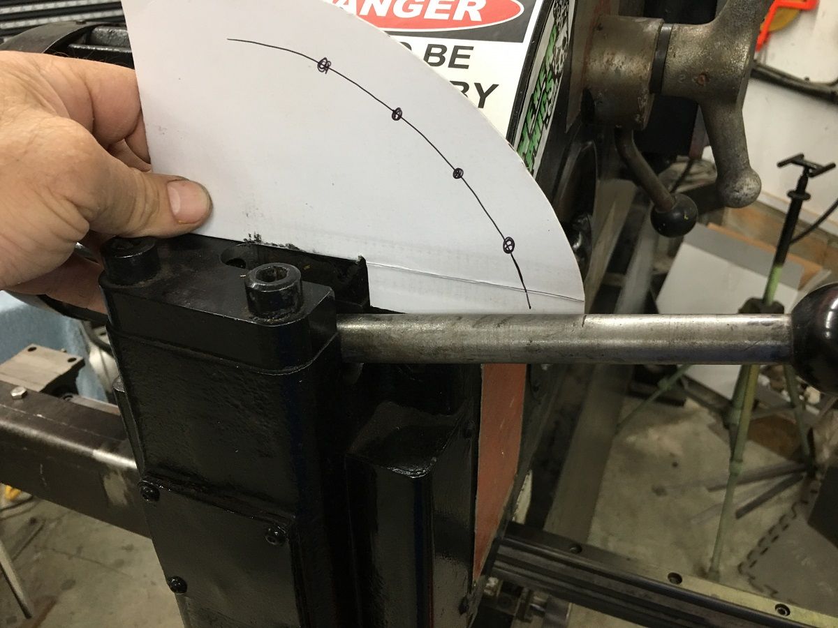
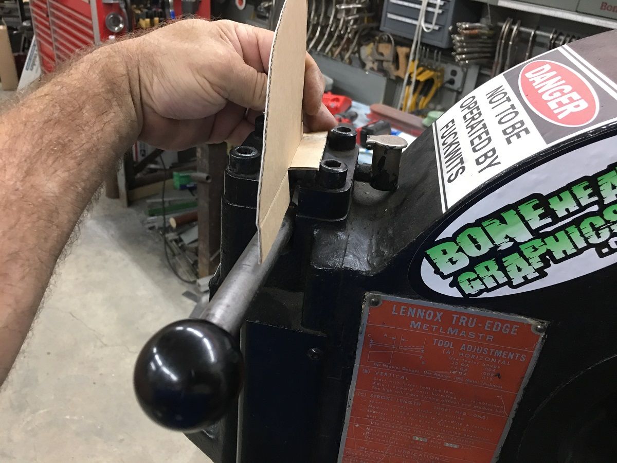
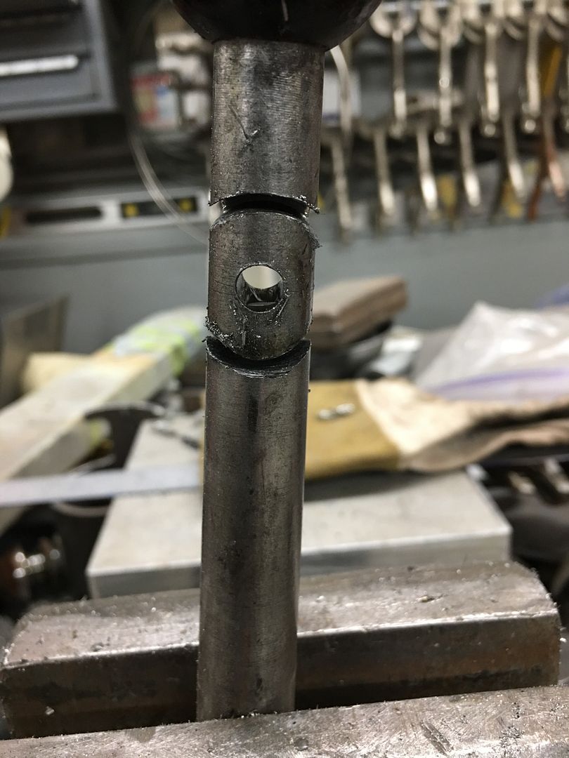
I got my copy in the mail today, so it starts with bolting on the bracket and marking the pull pin location holes onto the original actuator. Then this is drilled up to a 1/4" hole, then a 1" hole saw is used to add a concave radius to match the pull pin housing, for a nicer TIG weld..
Housing TIG welded in place....

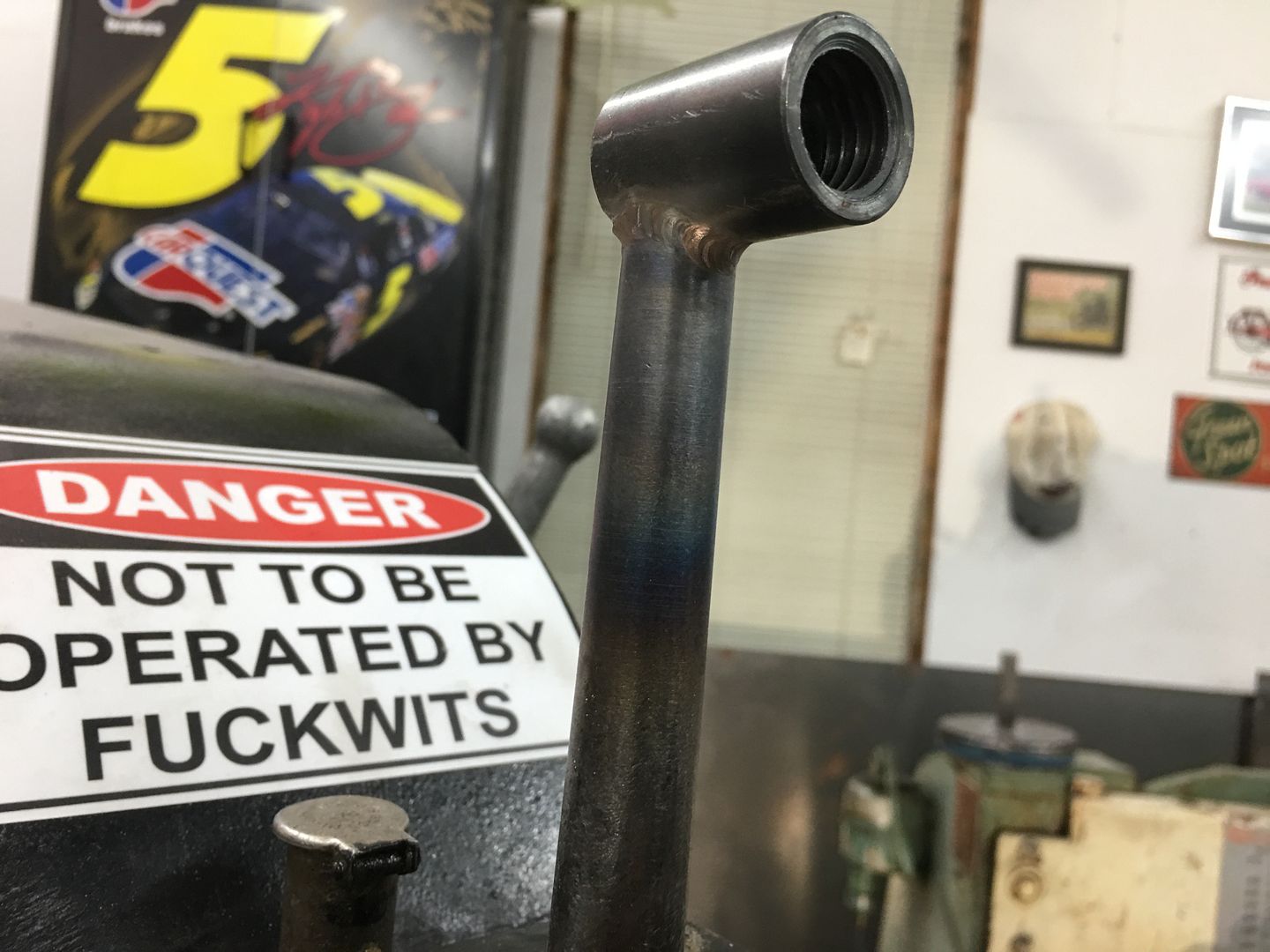
Assembled....
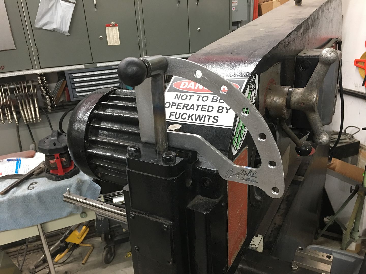
Action shot.....
This should save quite a bit of adjustment for the next set of louvers...
) I posted up a "sketch" of my thoughts on the subject … using a bolt-on bracket that would use existing hardware..
Mike Wagner (Cornfield Customs) has better capability in machinery and cutting parts, and took it from there to make a prototype bracket using the bolt on design, and a slight modification of the original actuator lever (includes welding)
I got my copy in the mail today, so it starts with bolting on the bracket and marking the pull pin location holes onto the original actuator. Then this is drilled up to a 1/4" hole, then a 1" hole saw is used to add a concave radius to match the pull pin housing, for a nicer TIG weld..
Housing TIG welded in place....
Assembled....
Action shot.....
This should save quite a bit of adjustment for the next set of louvers...
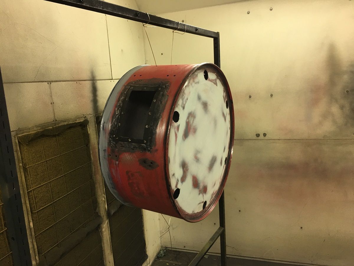
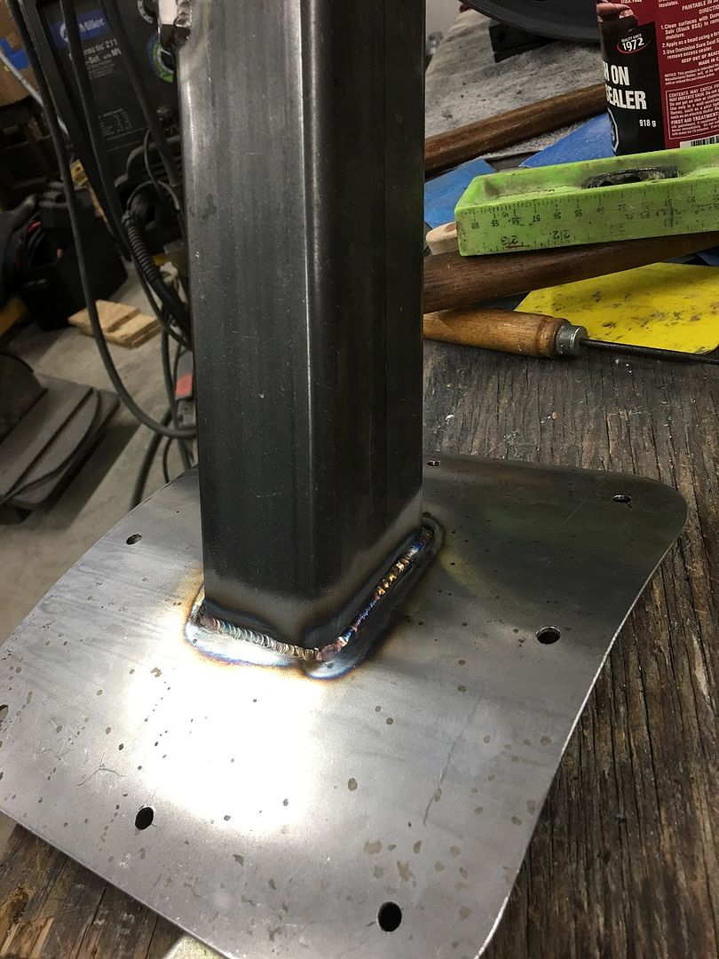
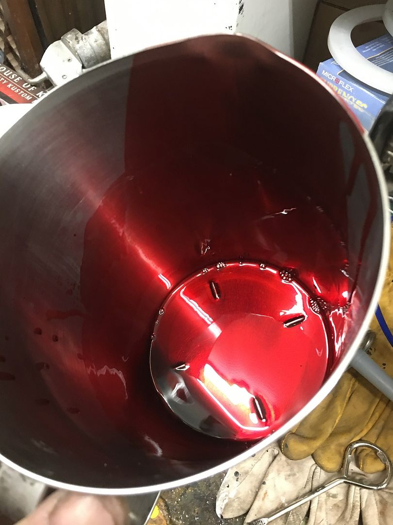
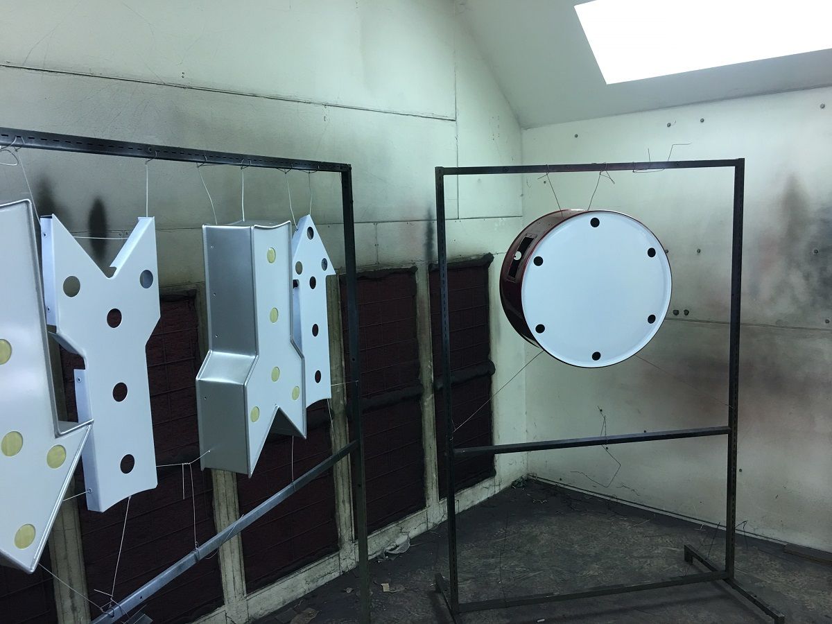
Sign progress, Fine tuning of some of the parts....
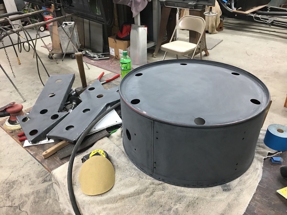
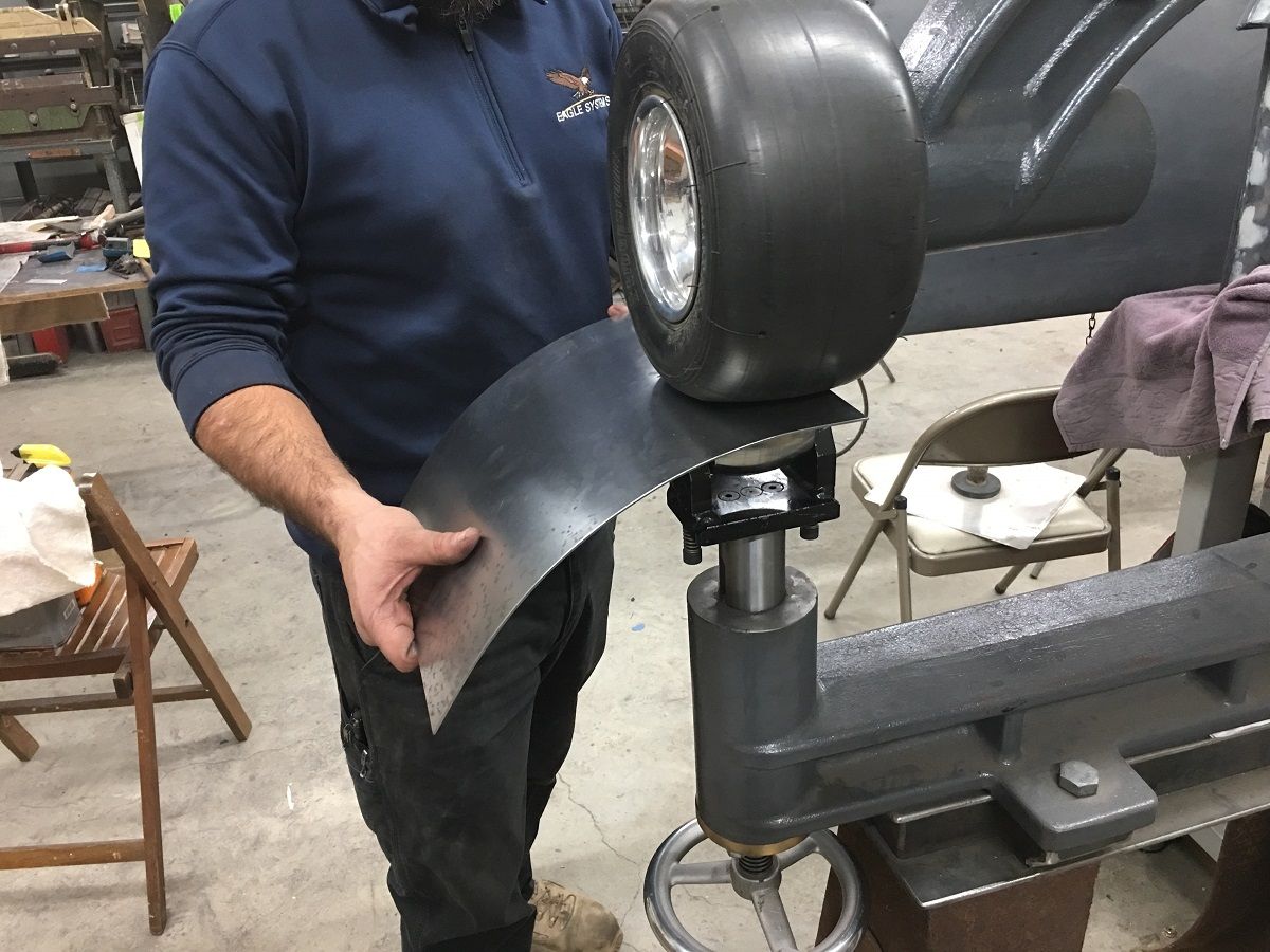
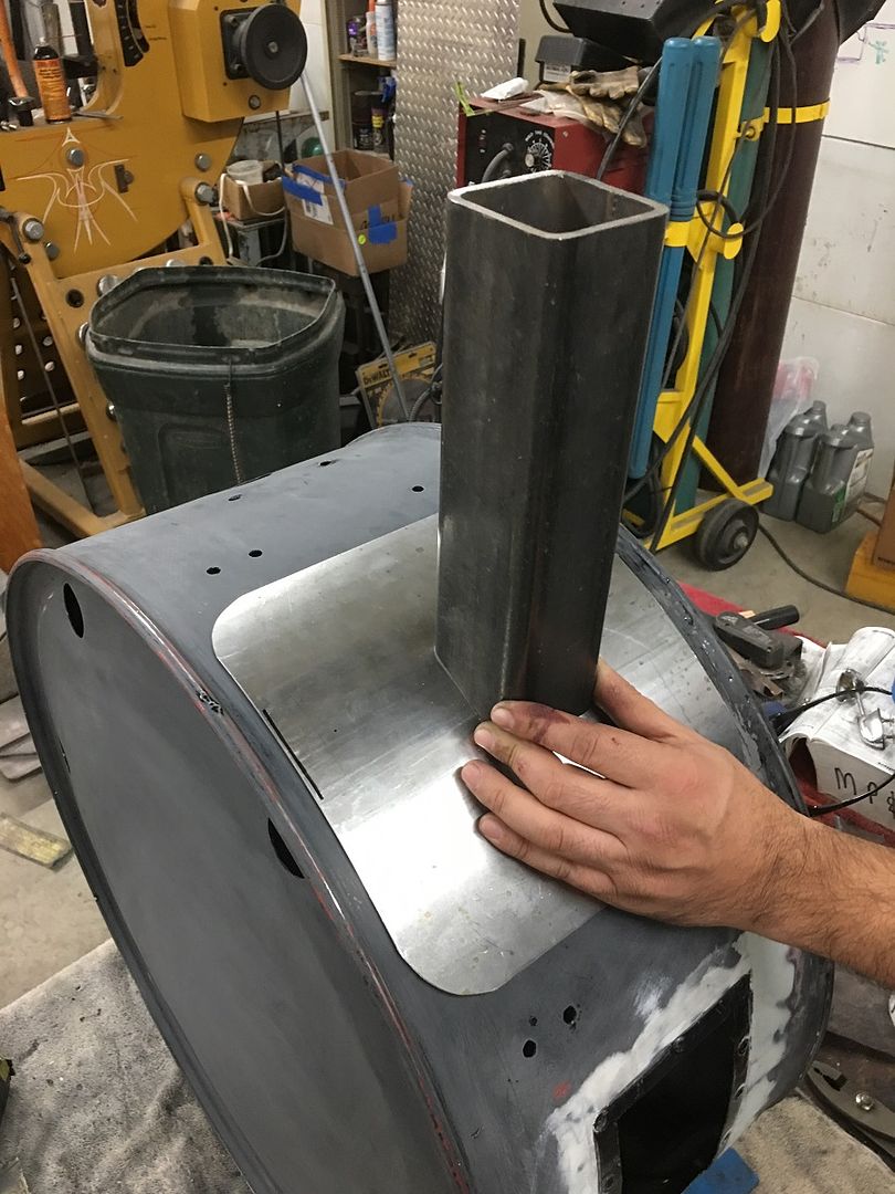
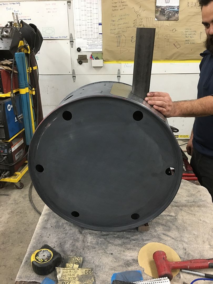
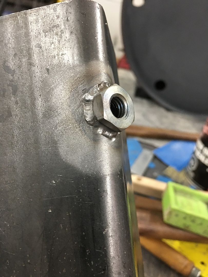
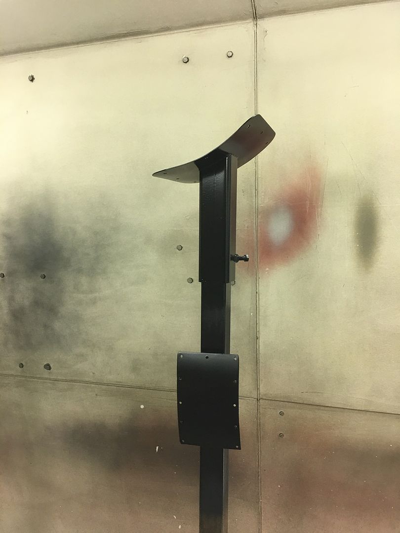
…..and for mounting it on the steel pole, this "shoe" is made of 14 gauge cold rolled and formed using the Go Kart slick.. The "sleeve" will slide over the pole and a set screw will hold it in place..
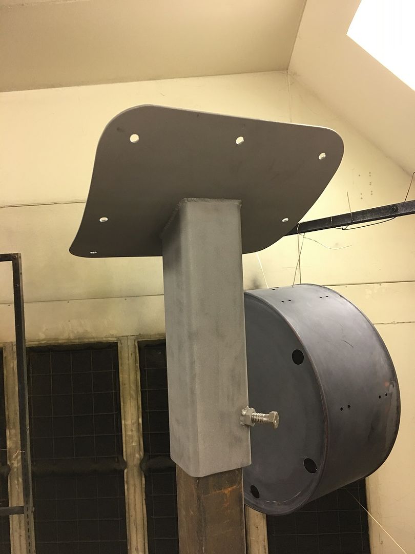
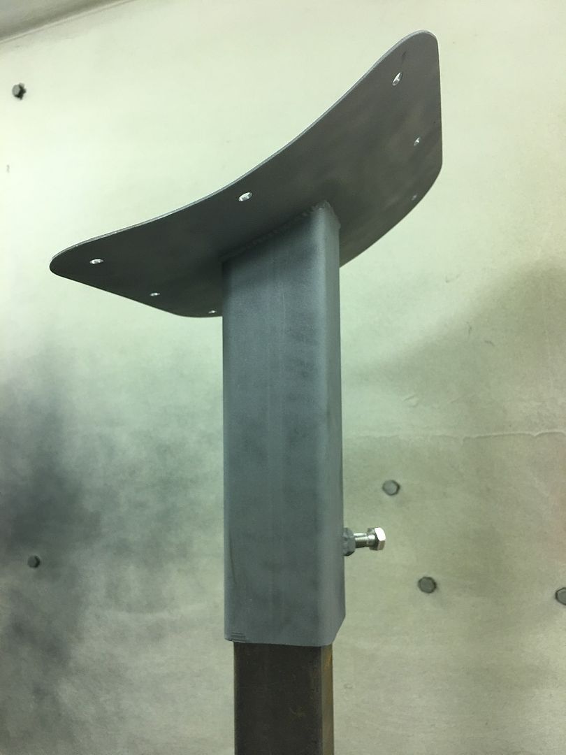
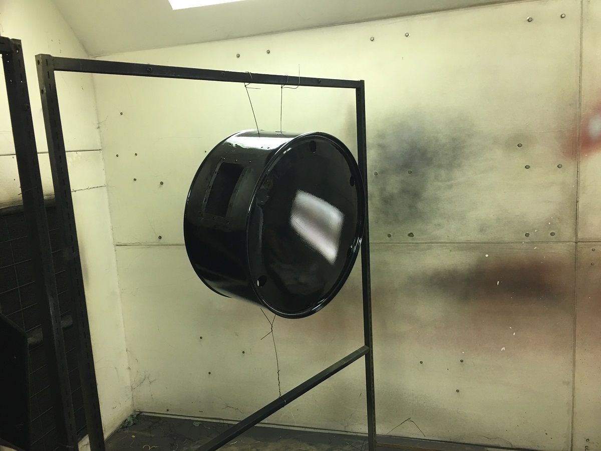
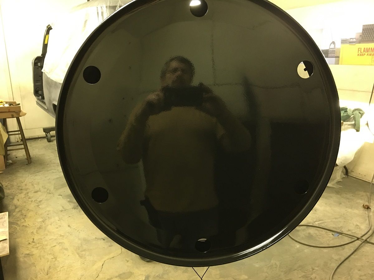
All ready for a splash of paint...
The sound mat is installed inside the wagon...
.
…..and for mounting it on the steel pole, this "shoe" is made of 14 gauge cold rolled and formed using the Go Kart slick.. The "sleeve" will slide over the pole and a set screw will hold it in place..
All ready for a splash of paint...
The sound mat is installed inside the wagon...
.
Last edited:
BORING HOP YARD
Well-known member
The sound mat is a nice milestone for you and your team.
I cant help but wonder if your customer understands the level of quality and the value of work being performed. I would assume on a project like this you have a schedule set up for payments as you go and not one big payment at the end.
So I was wondering what the customers point of view is. "Don't care how much its going to cost I got to have this car done to the max" "I trust you, make me happy, send me the bill" or " I have to have Robert restore the car, he's the best and that's what I want"
Sorry if this is sticking my nose in places where it don't belong.
Much respect!
Greg
QwikKotaTx
Well-known member
Nice job on that handle and bracket.
Nice job on that handle and bracket.
Thanks for checking out the thread!
The sound mat is a nice milestone for you and your team.
I cant help but wonder if your customer understands the level of quality and the value of work being performed. I would assume on a project like this you have a schedule set up for payments as you go and not one big payment at the end.
So I was wondering what the customers point of view is. "Don't care how much its going to cost I got to have this car done to the max" "I trust you, make me happy, send me the bill" or " I have to have Robert restore the car, he's the best and that's what I want"
Sorry if this is sticking my nose in places where it don't belong.
Much respect!
Greg
Not sure on the point of view, but I've offered to send some portions out for completion elsewhere to try and speed up the progress a bit, and she's said for me to take care of it in our shop.. This is a part time shop, with the day job needed for health insurance... so she does understand the time limitation, especially when work travel interferes. We normally let the material/labor balance get to a pre-determined amount, then I'll let her know to drop off a check....
xtremek
Well-known member
Very nice work
BORING HOP YARD
Well-known member
Sounds like your customer has 100 percent faith in you and expects you will make it to a level that will make her happy. The sign is killer, cant wait to see it assembled and maybe see it completed and hung up.
Thanks for sharing
Thanks for sharing
Bob Heine
ALLIANCE MEMBER
Awesome sign!
BORING HOP YARD
Well-known member
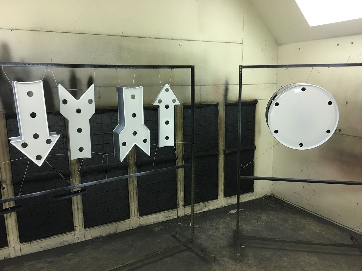
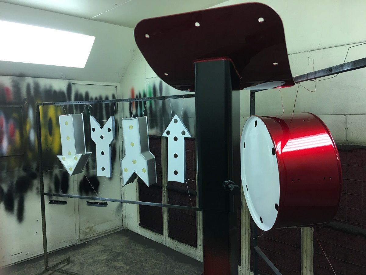
Nice work! Hard to believe 99% of the sign was flat sheet stock when it was started.
The lights look great as well.
The lights look great as well.
xtremek
Well-known member
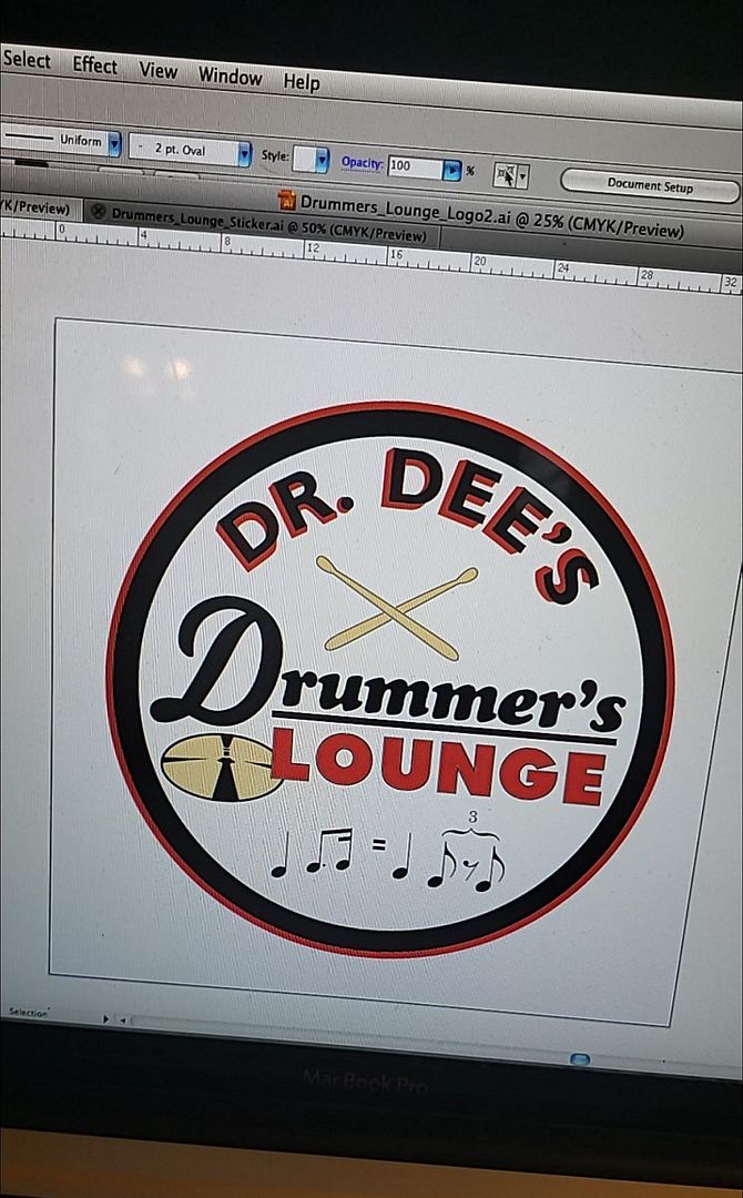
Will the graphics be vinyl or paint?
Boosted1
Well-known member
The sign is cool.
Very nicely done.
Very nicely done.
Thanks guys!
Kind of a man cave on steroids. He has a "lounge" complete with stage for the band and all..
Vinyl
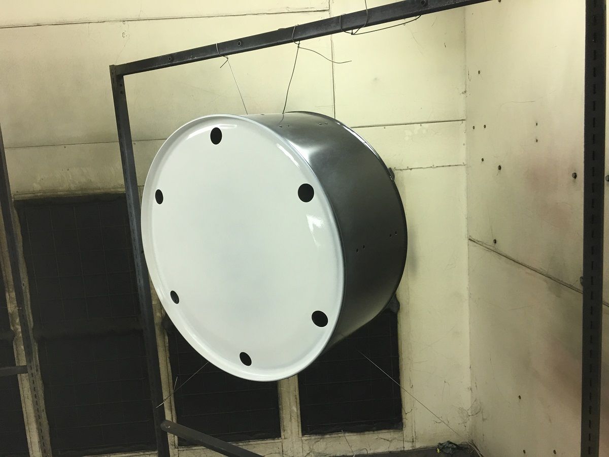
Nice sign, love the chrome drum hardware being utilized.
Is the sign being made for a man-cave or is it for an actual business?
Kind of a man cave on steroids. He has a "lounge" complete with stage for the band and all..
Will the graphics be vinyl or paint?
Vinyl
zmotorsports
ALLIANCE MEMBER
Beautiful work as always Robert.
Seeing these pictures almost makes me miss the days of doing paint and body work......Almost.
Seeing these pictures almost makes me miss the days of doing paint and body work......Almost.