I have about three different versions, that one has two screws that came with it, one with the 3/8 shank, the other 1/4 shank. That does hold rather well, we've also found if you're having difficulty with wobble on the cutoff wheel and can't seem to get it out, try flipping to the other side...

You are using an out of date browser. It may not display this or other websites correctly.
You should upgrade or use an alternative browser.
You should upgrade or use an alternative browser.
MP&C Shop Projects
- Thread starter MP&C
- Start date
Offcenter12
Well-known member
Thanks Robert. It's beginning to warm up here so I need to actually do something instead of just thinking about it. 
John
John
xtremek
Well-known member
While the intent of this thread is obvious and accurately stated (and GREATLY appreciated), I'm glad you're taking us to the end on these projects.

shortykorte
Well-known member
Looking forward to the Divco project and the dent repair process. Is this going to be your vehicle? I remember the shed roof collapsing but can’t remember if it’s your van.
Shorty Korte
Always remember quality in QST
Sent from my iPhone using Garage Journal
Shorty Korte
Always remember quality in QST
Sent from my iPhone using Garage Journal
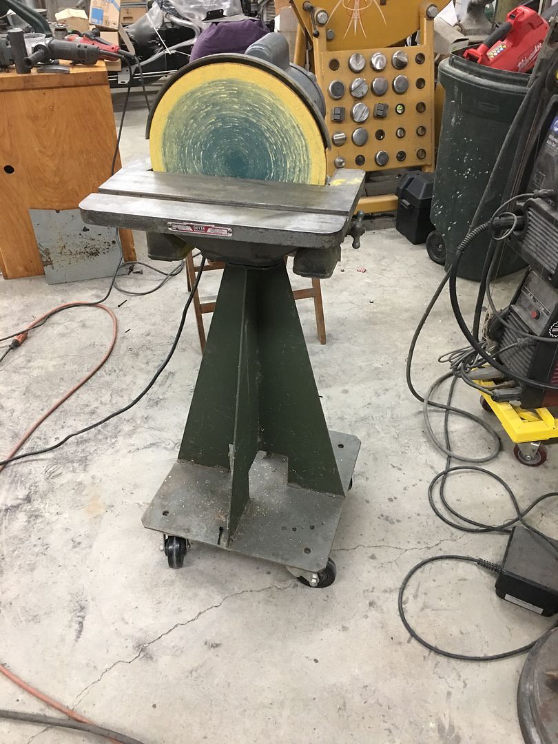
Some spring cleaning.... Picked up a 12" disc sander quite a few months back, and Mike has been using this on the floor.. So I decided to help the guy out and put it at a more useable height... Added a "bolting framework" to the top of one of the paint tripods, already set up with casters so you can push it in the corner....
Rivnuts installed since I didn't have bolts in stock long enough to go all the way through..
Ready for some sanding...
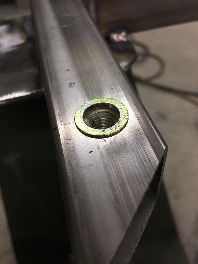
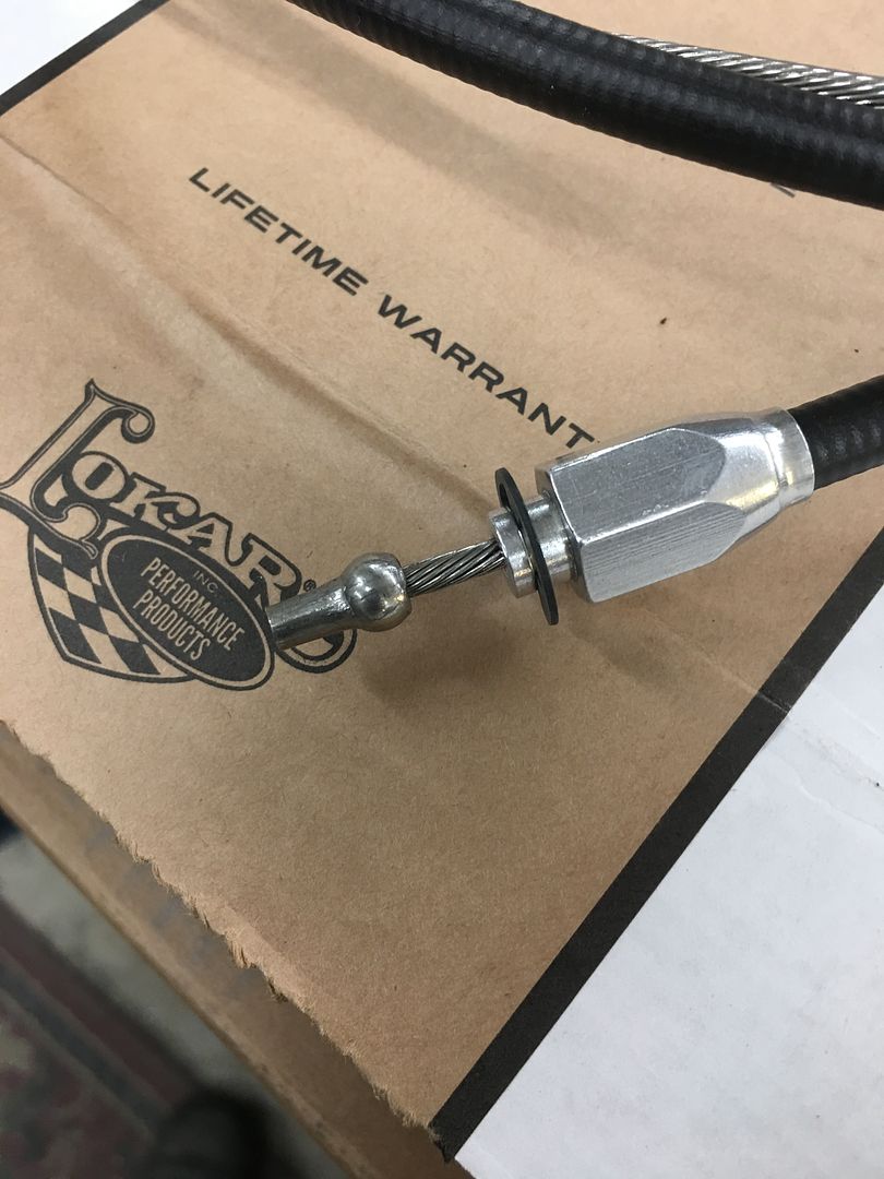
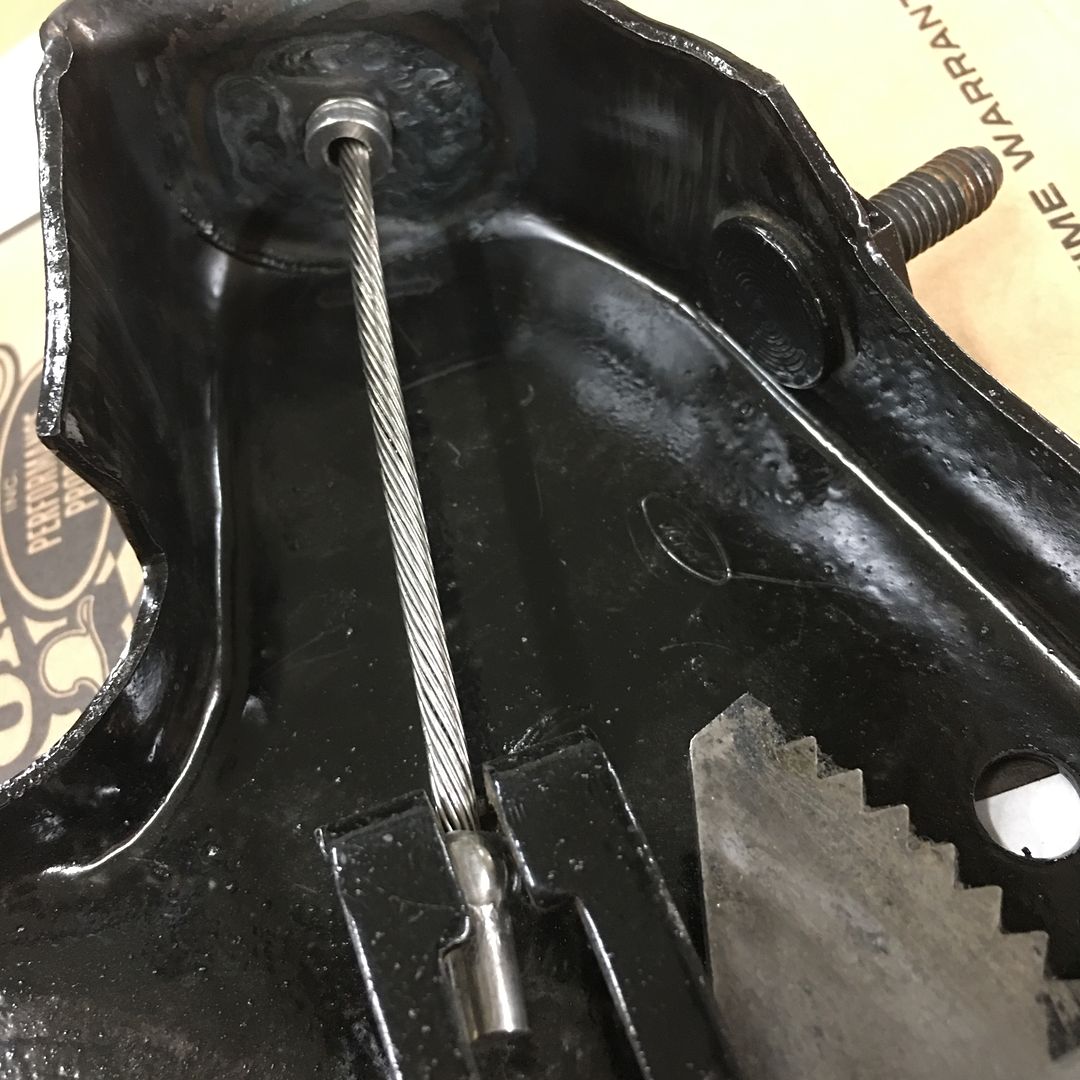
Dana dropped off the new brake cables for the wagon the other day. The single cable that attaches to the pedal has a shouldered ferrule that sits in the bottom of the parking brake bracket. Only this shoulder was much too small for the factory hole, the Hex portion almost pulled through the hole.
I considered making an adapter sleeve on the lathe, but the figured resizing the hole would be quicker. Found a nice thick 3/8 flat washer in stock that fit the ferrule shoulder perfectly and matched the thickness of the parking brake bracket. In order to get the weld heat farther from the 3/8 hole, the bracket opening was oversized up to 7/8" (largest step drill that I could find) and the washer slightly downsized to fit.. Some 3/8 standoffs made a quick arbor for the drill, and the die grinder does the rest. we had our correct size in about a minute..
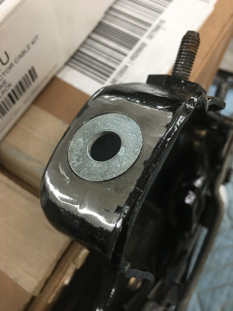
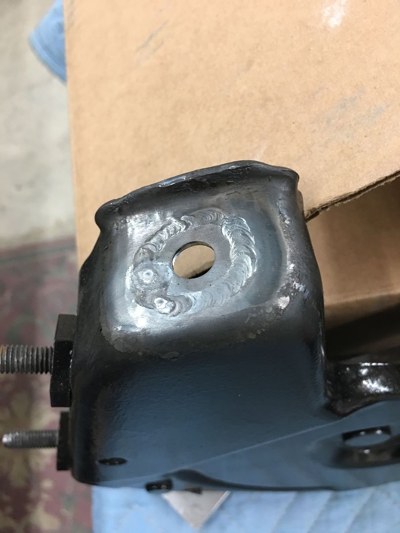
Installed, much better fit... Now Vince needs to do some touch up on the paint!
Rivnuts installed since I didn't have bolts in stock long enough to go all the way through..
Ready for some sanding...
Dana dropped off the new brake cables for the wagon the other day. The single cable that attaches to the pedal has a shouldered ferrule that sits in the bottom of the parking brake bracket. Only this shoulder was much too small for the factory hole, the Hex portion almost pulled through the hole.
I considered making an adapter sleeve on the lathe, but the figured resizing the hole would be quicker. Found a nice thick 3/8 flat washer in stock that fit the ferrule shoulder perfectly and matched the thickness of the parking brake bracket. In order to get the weld heat farther from the 3/8 hole, the bracket opening was oversized up to 7/8" (largest step drill that I could find) and the washer slightly downsized to fit.. Some 3/8 standoffs made a quick arbor for the drill, and the die grinder does the rest. we had our correct size in about a minute..
Installed, much better fit... Now Vince needs to do some touch up on the paint!
Slednut
Well-known member

Offcenter12
Well-known member
Robert,
That washer between the standoffs with the drill/die grinder trick is exceptionally clever Sir! A handheld lathe so to speak.
That washer between the standoffs with the drill/die grinder trick is exceptionally clever Sir! A handheld lathe so to speak.
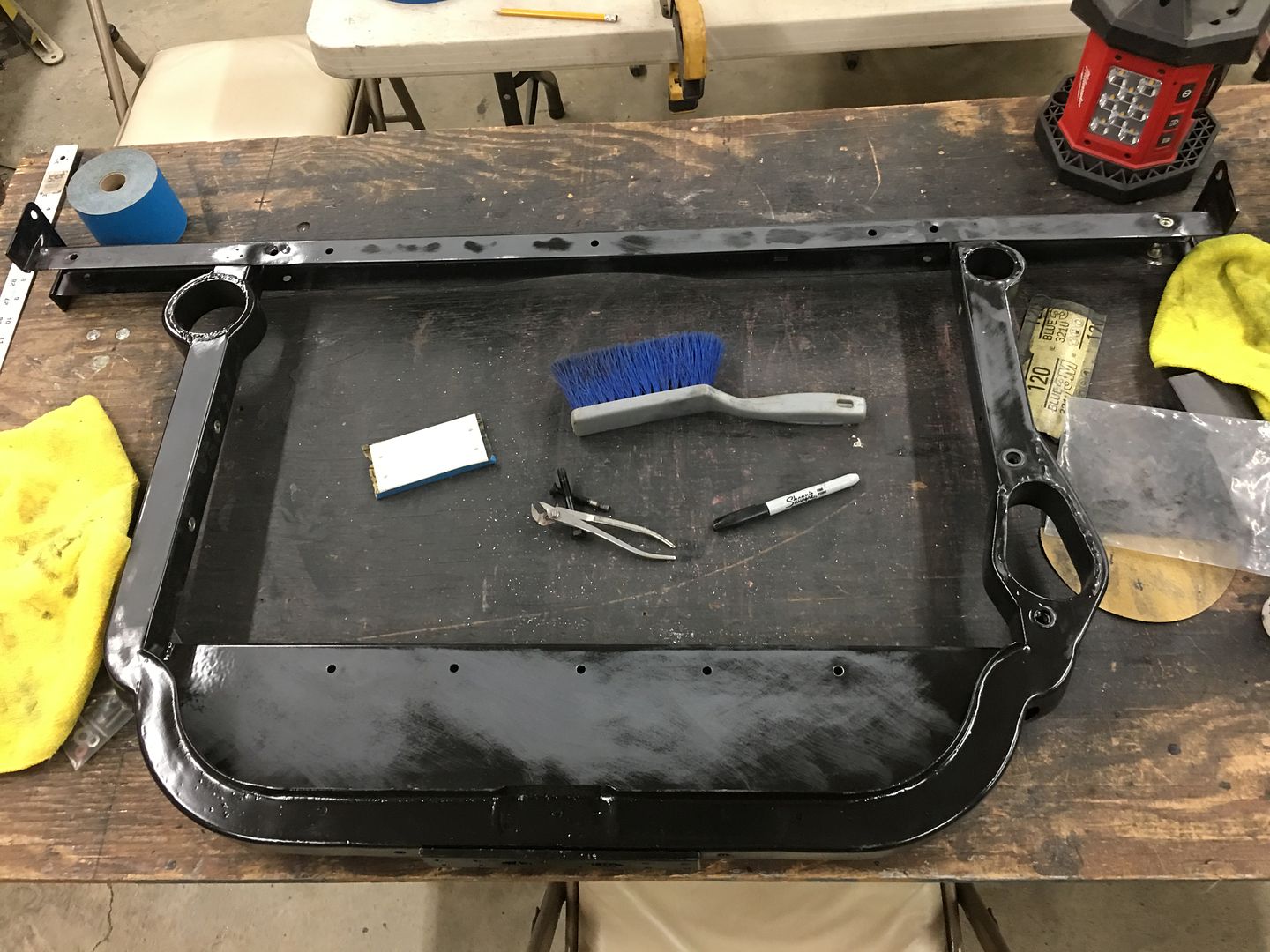
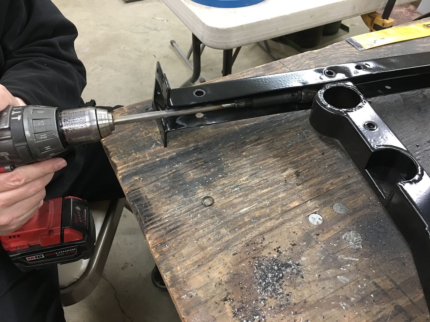
We're in the middle of blocking paint today on the core support and happened to notice someone forgot to add the holes in the new vertical uprights for the light wires to go across above the radiator.
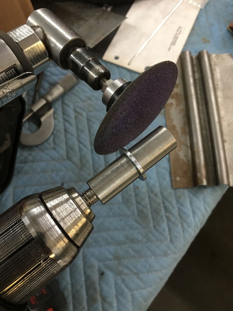
We have some rotary cutters that would do the trick but they are a bit short to reach from the outside (to keep things perpendicular) so lets make an extension. The set screw for the spring loaded center point is a 5/16-24 and we happened to have some in stock. So we used a piece of stainless fuel line and plug welded a stud in one end and a plug in the other for tightening in the drill chuck..
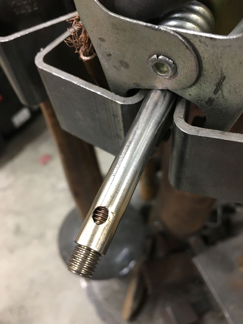
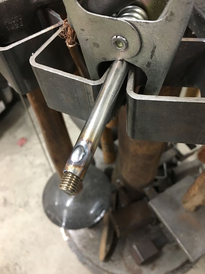
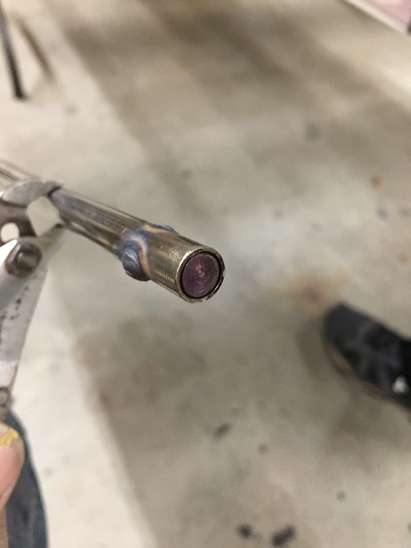
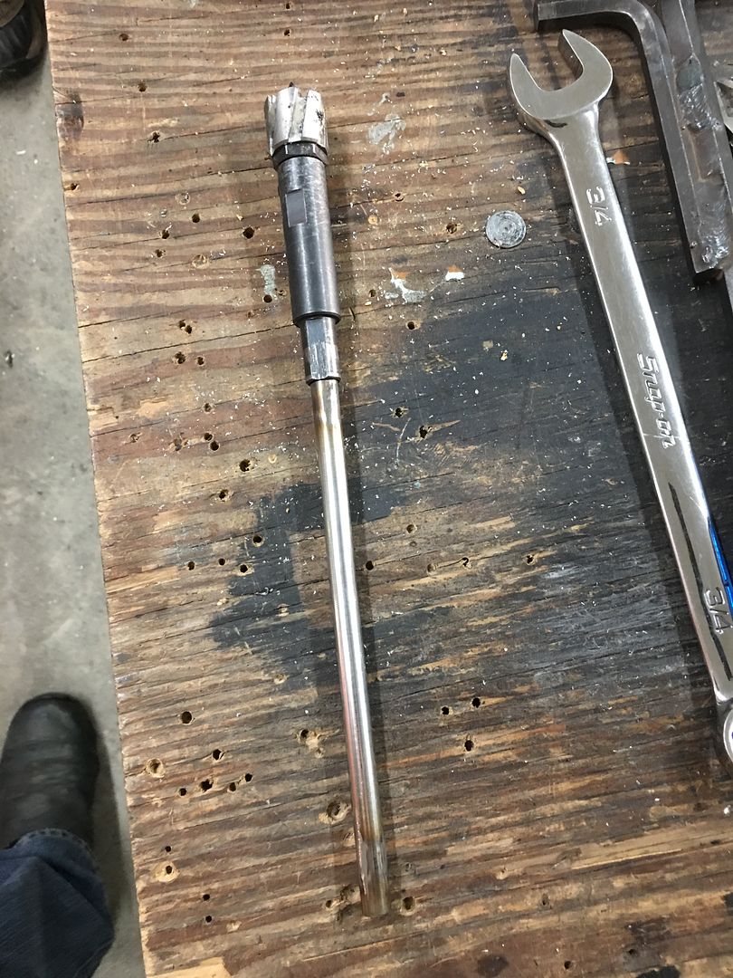
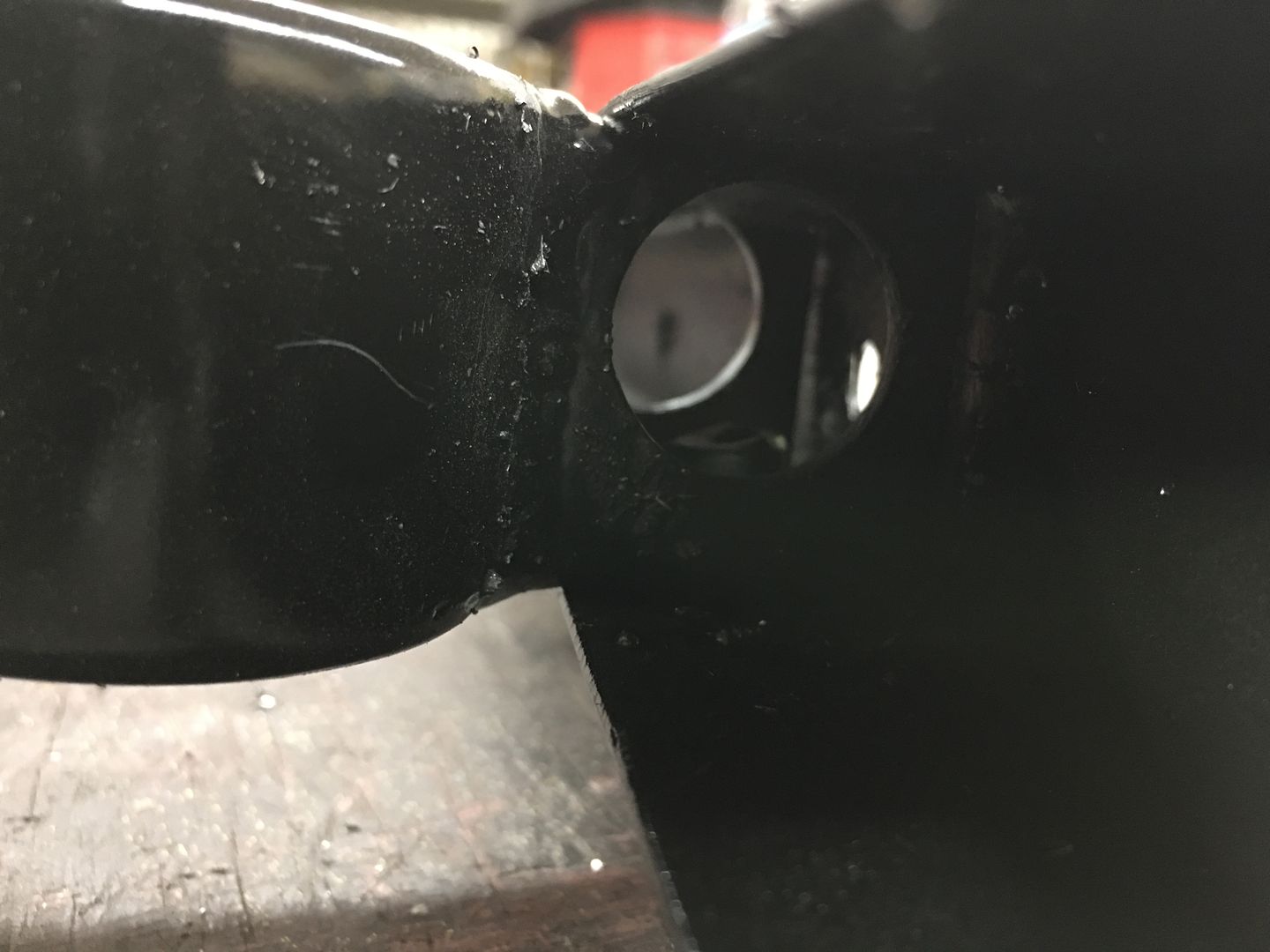
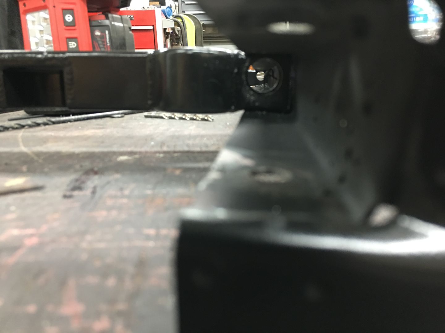
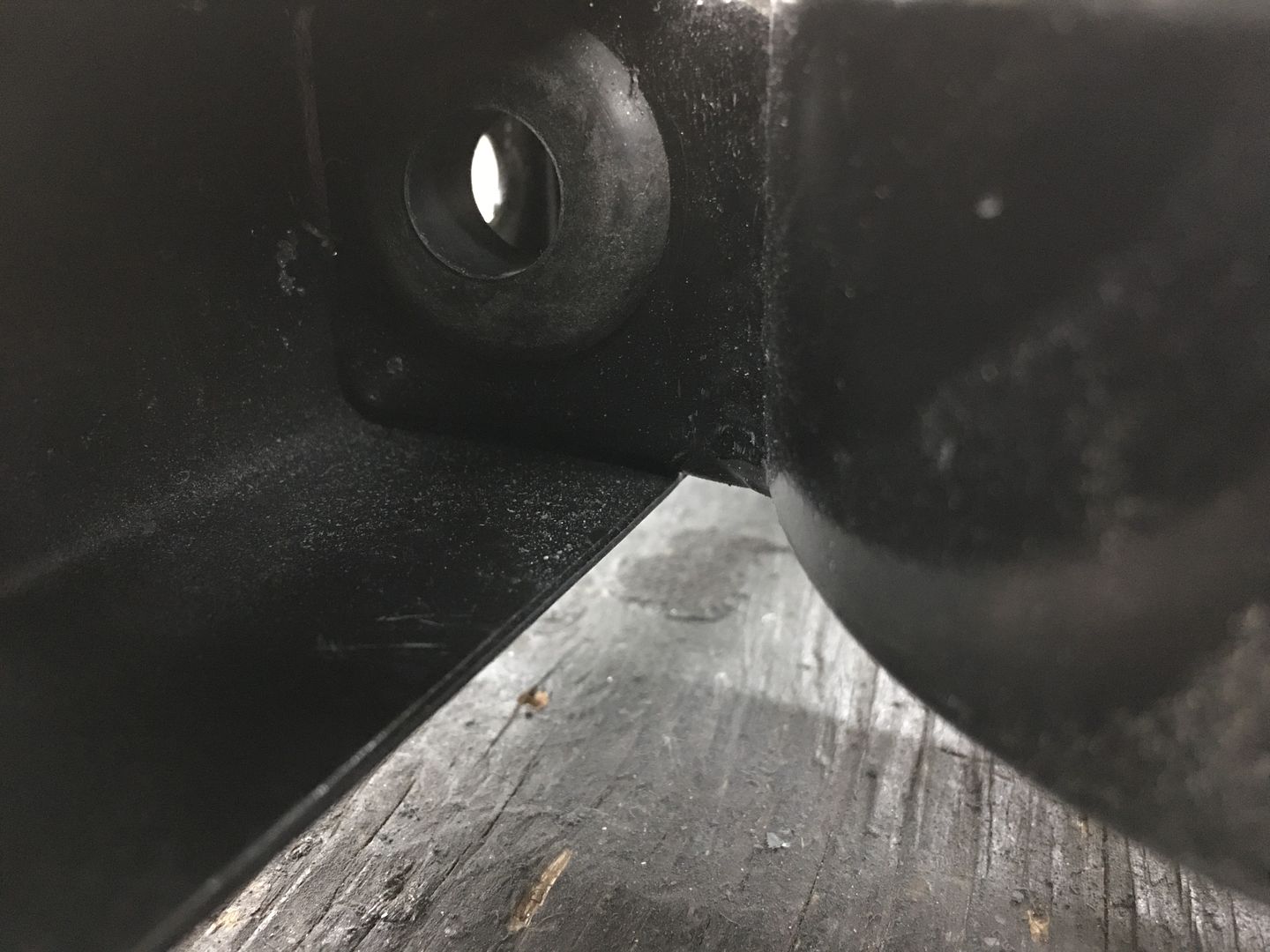
Holes drilled, deburred, and grommet test fitted..
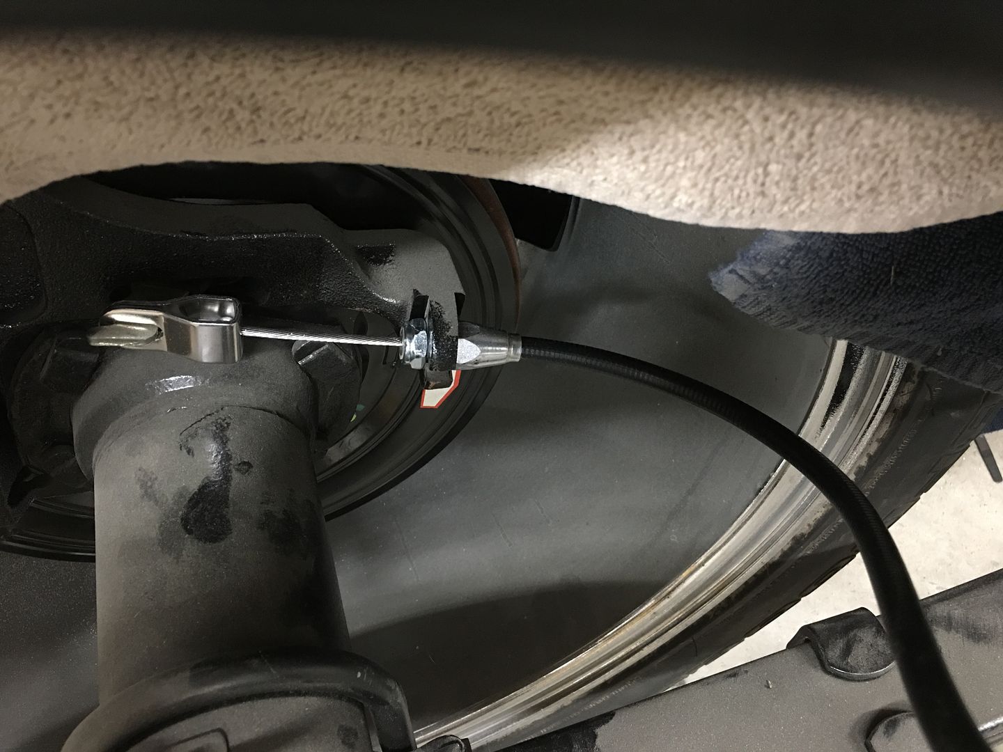
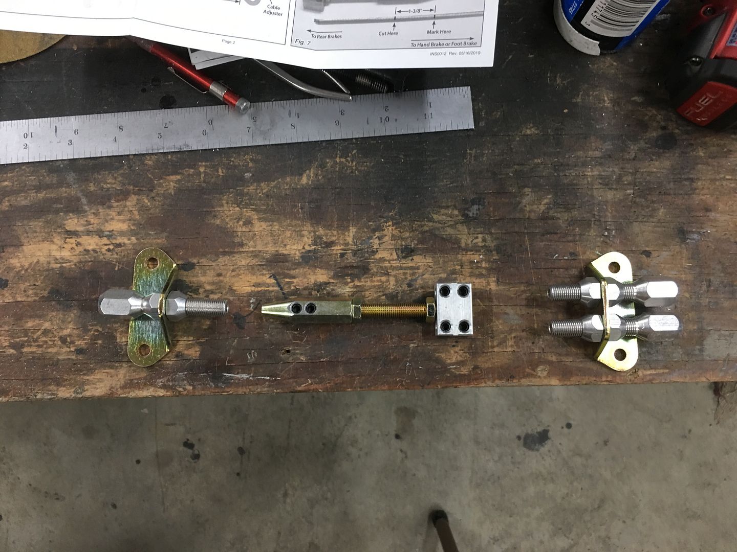
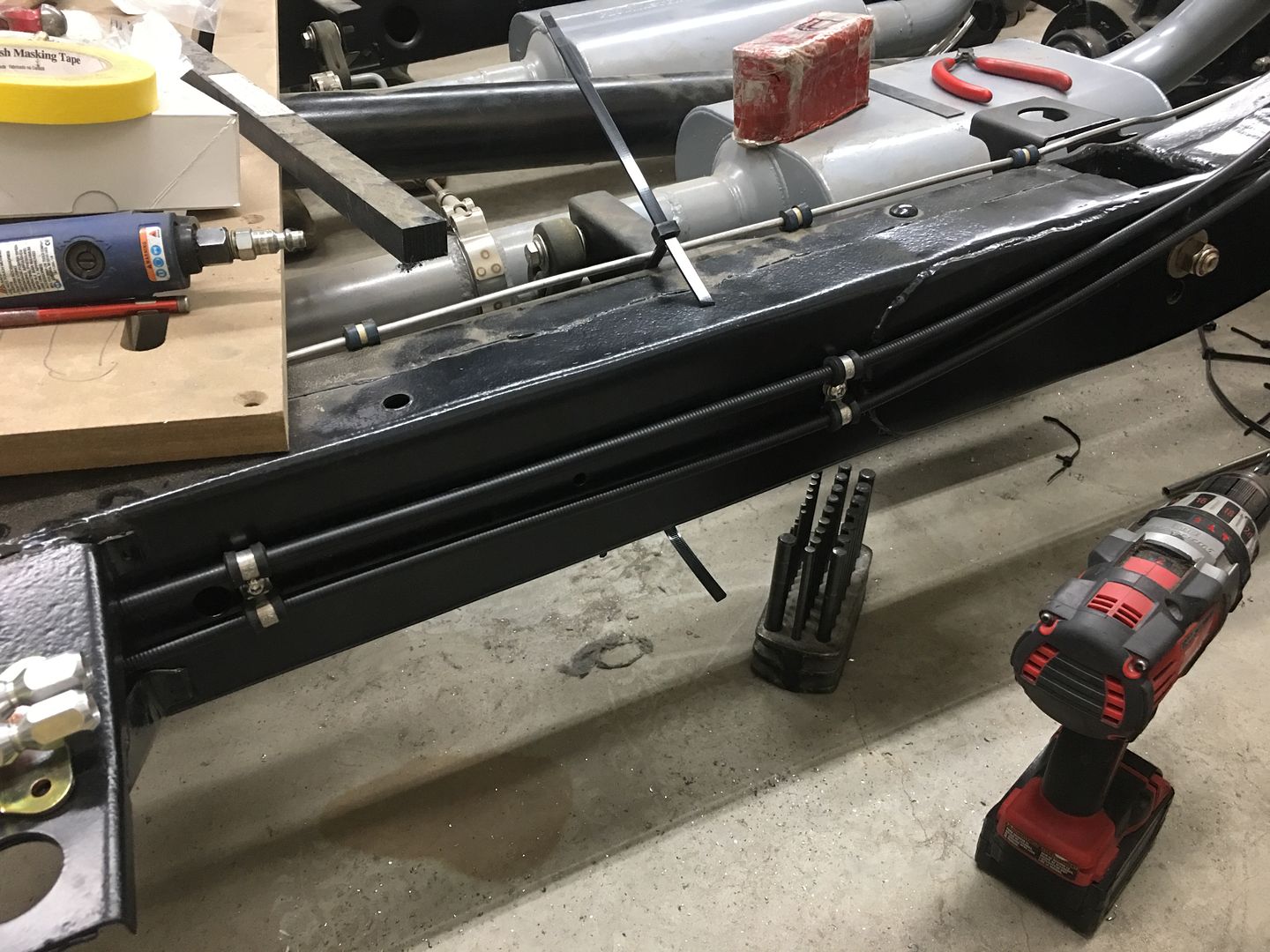
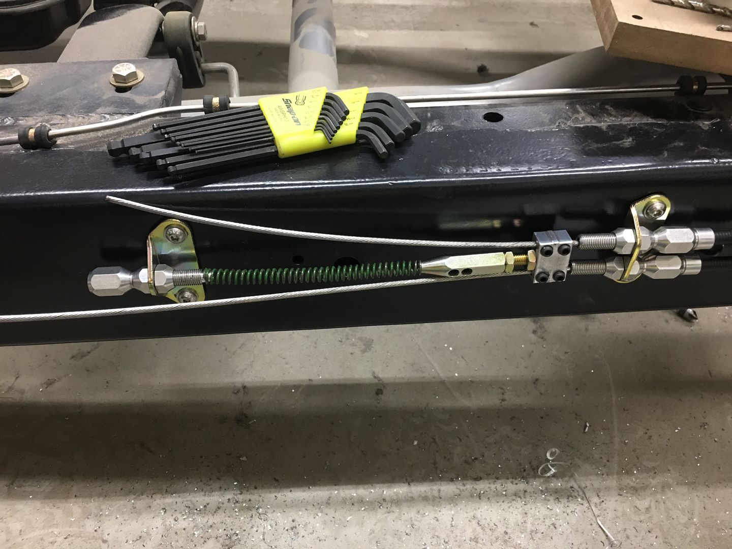
Now for a test fit of our Parking brake lines to mock up the routing prior to adding rivet nuts and adel clamps...
Looks like we had one more part to chose from...
We have some rotary cutters that would do the trick but they are a bit short to reach from the outside (to keep things perpendicular) so lets make an extension. The set screw for the spring loaded center point is a 5/16-24 and we happened to have some in stock. So we used a piece of stainless fuel line and plug welded a stud in one end and a plug in the other for tightening in the drill chuck..
Holes drilled, deburred, and grommet test fitted..
Now for a test fit of our Parking brake lines to mock up the routing prior to adding rivet nuts and adel clamps...
…...what did you do about the one into two transition?
Looks like we had one more part to chose from...
Slednut
Well-known member
Looks like we had one more part to chose from...
Thanks for the reply, I'll see if I can order that piece, I only ordered the rear (long) cables because I knew I could use one of the short cables that was included with my disc brake kit to go between the e-brake pedal and the 1 into 2 transition.
BassProCamaro97
Well-known member
Just wanted to pop in and say I used your patch panel method to the letter on a lower door skin patch (after warping it the first time) and it came out better than any patch I've done. Thanks again for all the knowledge you share!!!!!!!!!!
~Jim~
~Jim~
xtremek
Well-known member
When I start my big project. I think I'm going to reread all 180+ pages (it'll be that long when I finally get to bring it into the shop.
zmotorsports
ALLIANCE MEMBER
Beautiful work on the cable fitment and grommets Robert. The devil is in the details.
Thanks for all the comments guys!
Thanks for the feedback Jim, glad the thread content is helping out!!
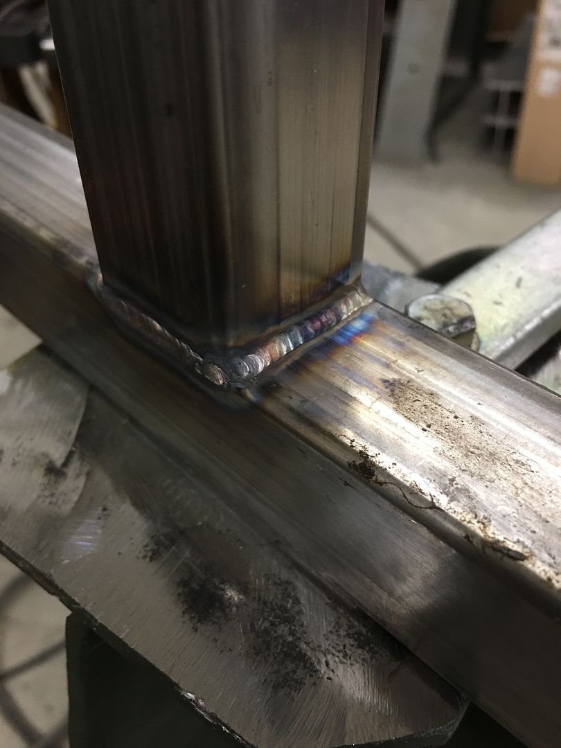
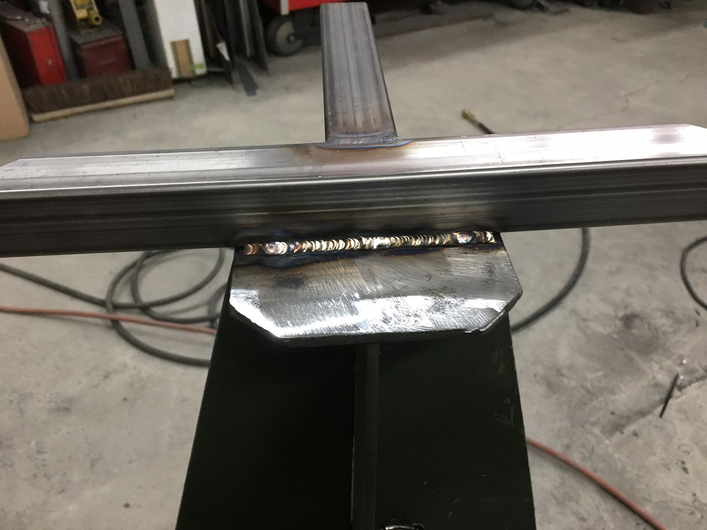
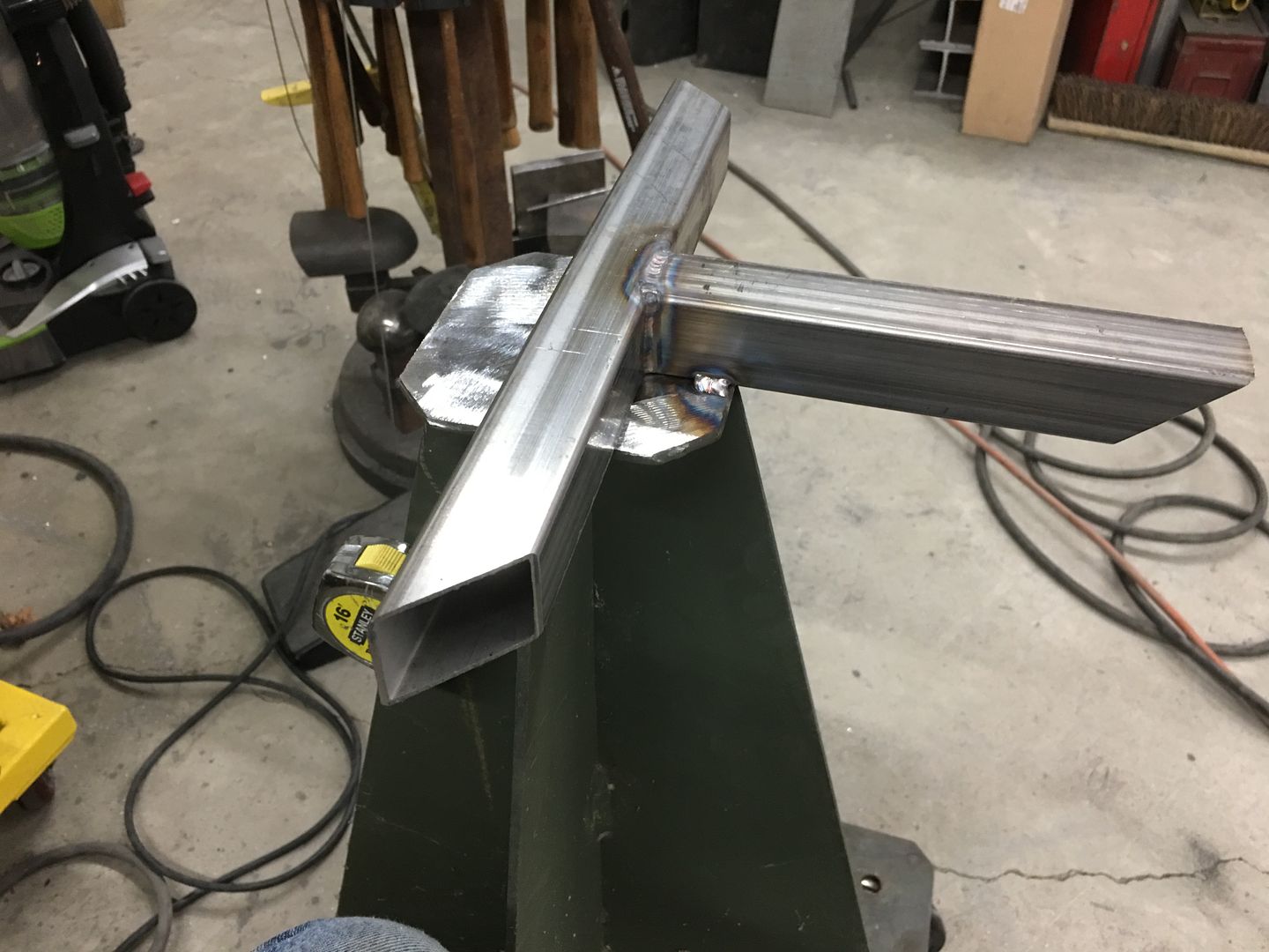
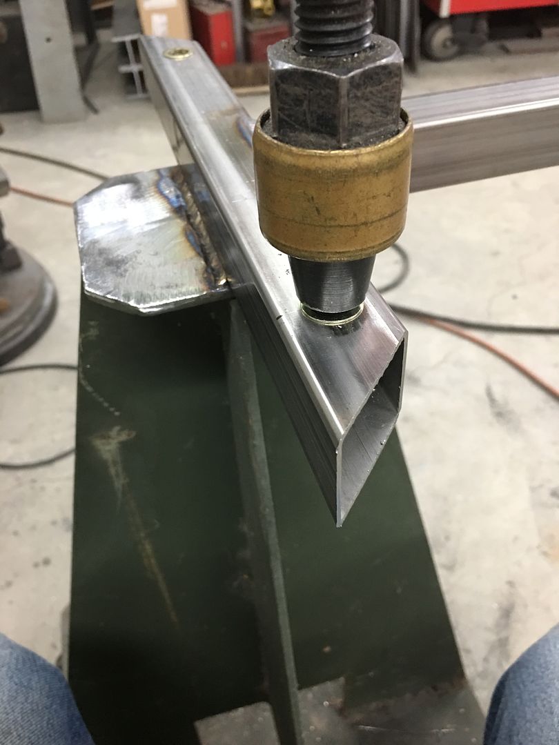
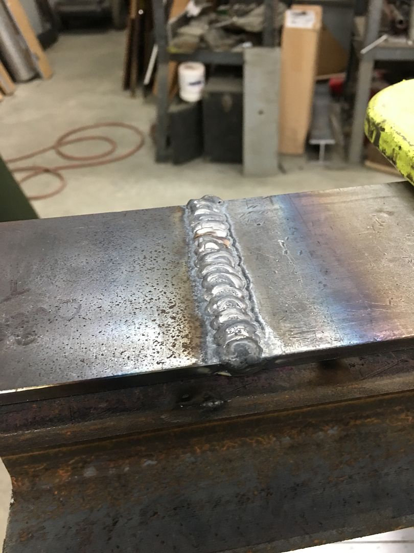
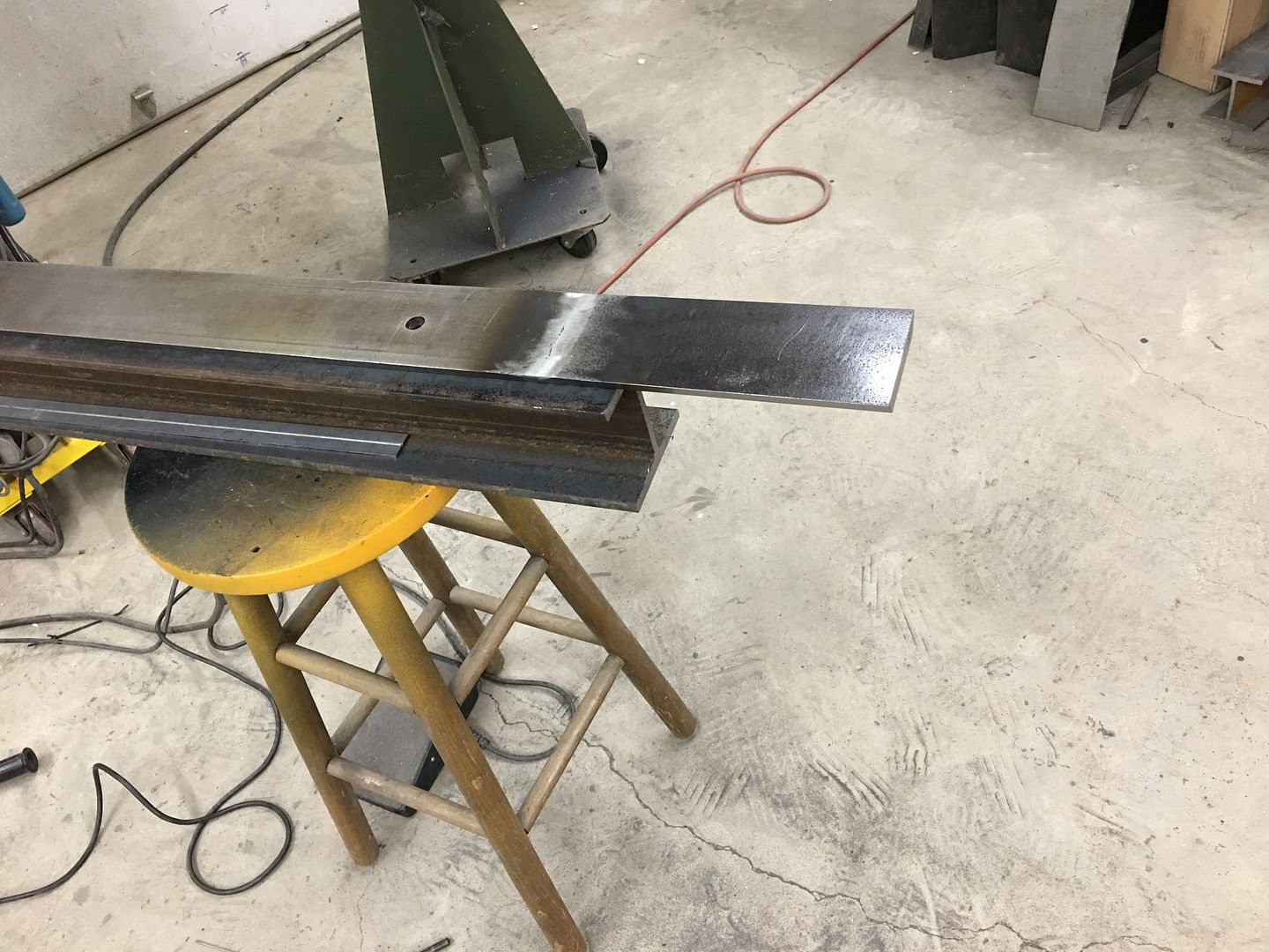
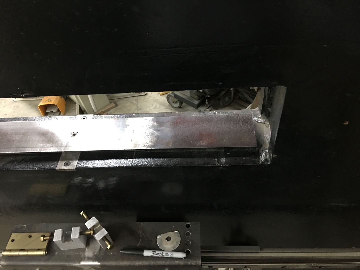
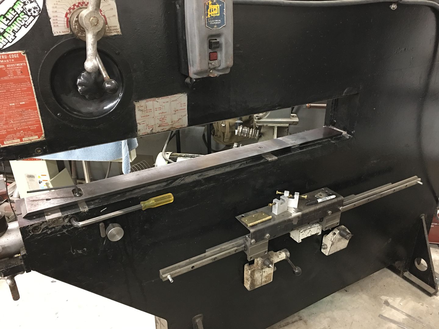
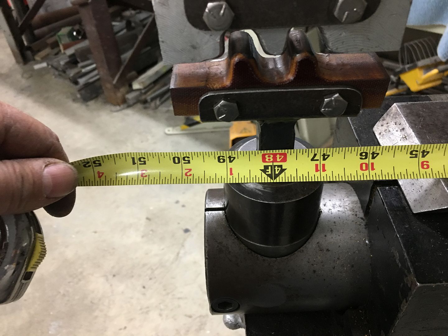
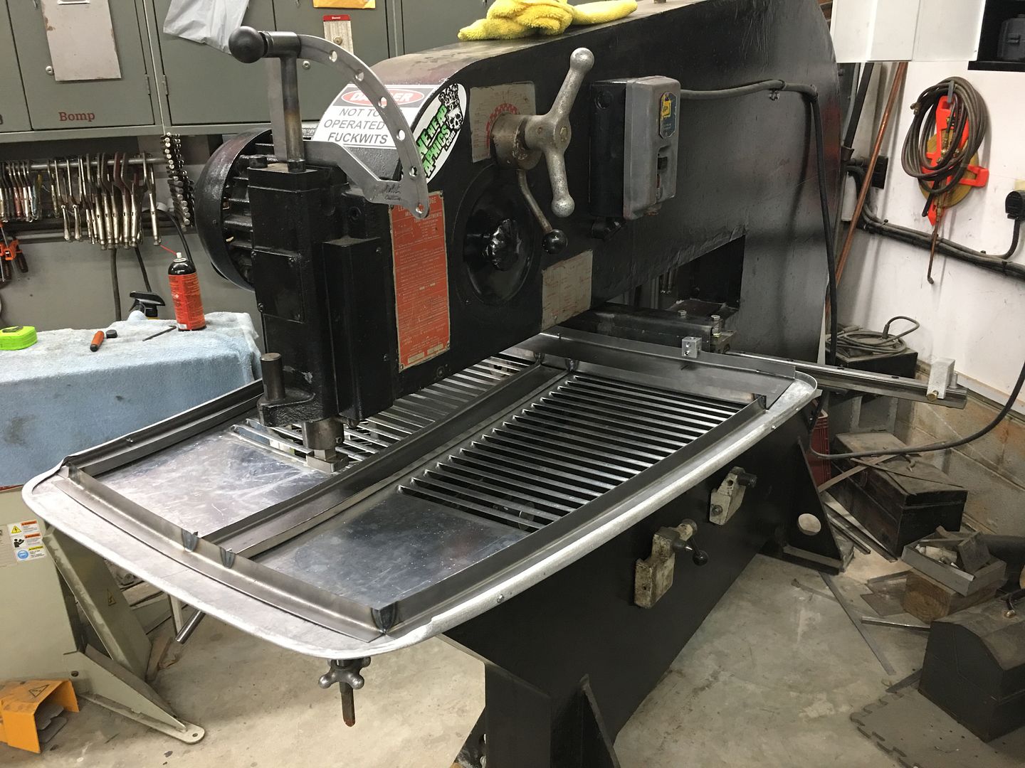
Last night was equipment maintenance of sorts... Finishing up our dovetail extensions on the Lennox Nibbler. When I had the set of dovetail extensions made we neglected to check BOTH the top and bottom. I pulled the top one off as it is used less frequently, and gave it to my machinist as a sample. As it were, the bottom is .045 thinner, and we just got this last piece back from surface grinding last night. Time to finish this job, all welded, cleaned up, and ready for the next louver job. The back edge of the dovetail to centerline of the dies is just shy of 48”. I think that will do us.
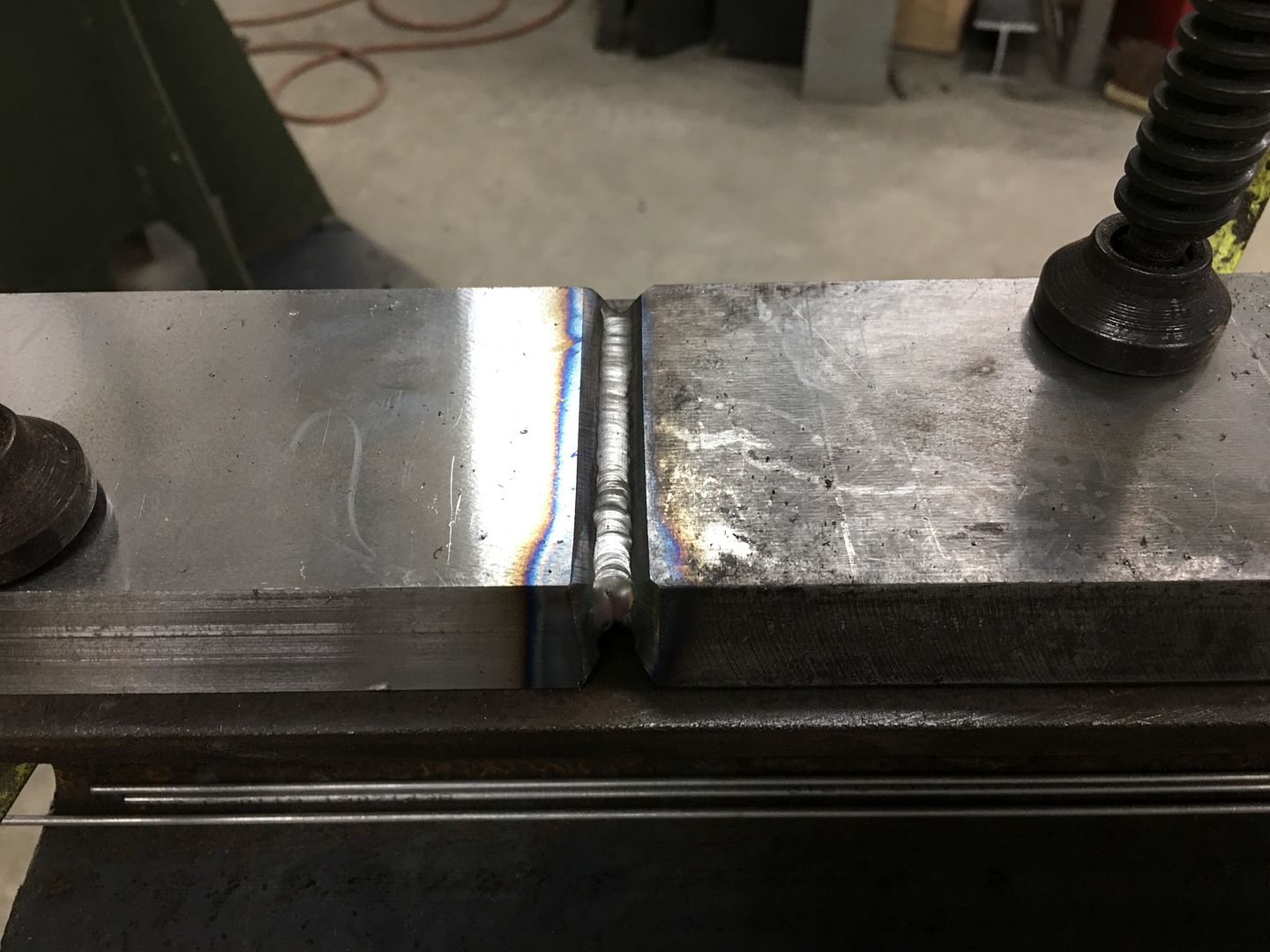
Final weld pass is not too pretty, but this side was "reflowed" to add some contraction for straightening the dovetail.
Just wanted to pop in and say I used your patch panel method to the letter on a lower door skin patch (after warping it the first time) and it came out better than any patch I've done. Thanks again for all the knowledge you share!!!!!!!!!!
~Jim~
Thanks for the feedback Jim, glad the thread content is helping out!!
Last night was equipment maintenance of sorts... Finishing up our dovetail extensions on the Lennox Nibbler. When I had the set of dovetail extensions made we neglected to check BOTH the top and bottom. I pulled the top one off as it is used less frequently, and gave it to my machinist as a sample. As it were, the bottom is .045 thinner, and we just got this last piece back from surface grinding last night. Time to finish this job, all welded, cleaned up, and ready for the next louver job. The back edge of the dovetail to centerline of the dies is just shy of 48”. I think that will do us.
Final weld pass is not too pretty, but this side was "reflowed" to add some contraction for straightening the dovetail.
With our adel clamps arrived, Mike and I worked on the brake cables while Vince was prepping things for paint...
.JPG)
.JPG)
I think he's having too much fun...
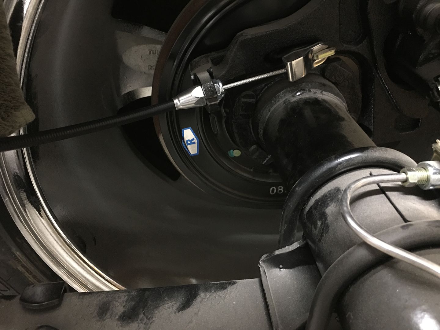
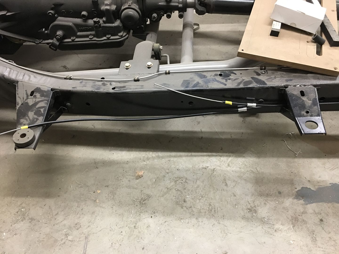
We had to wait for -5 clamps as these were snug enough to hold the cable from moving. This allows us to set the length to the backing plate such that it clears the frame during suspension travel..
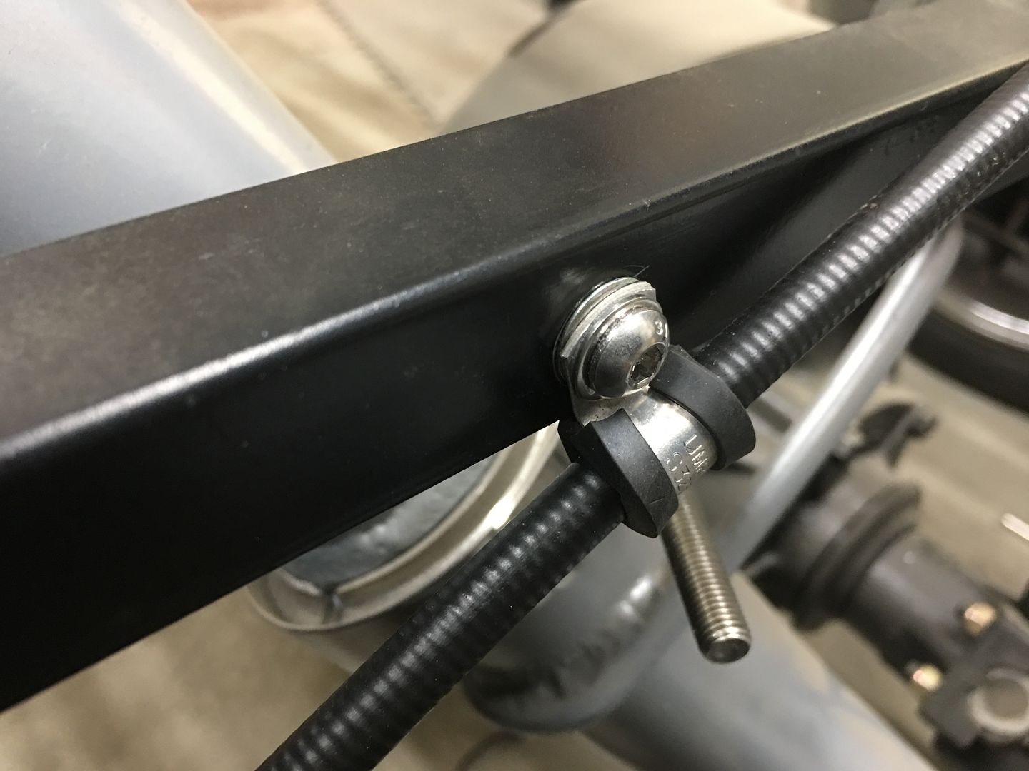
The clamps were held in place using rivet nuts installed into the frame. Here is a video showing rivet nuts and the proper installation:
Outer sheaths are marked for trimming..
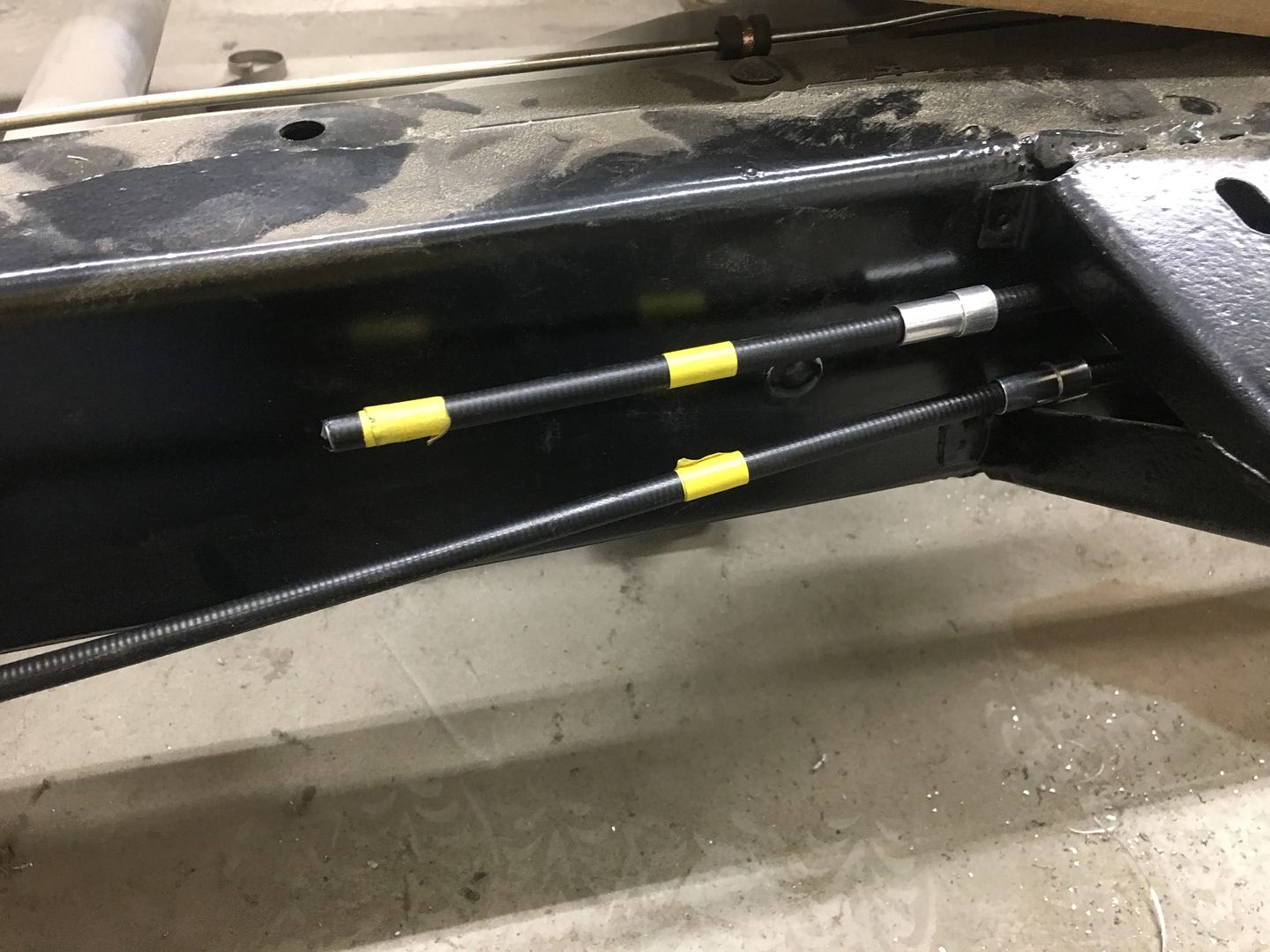
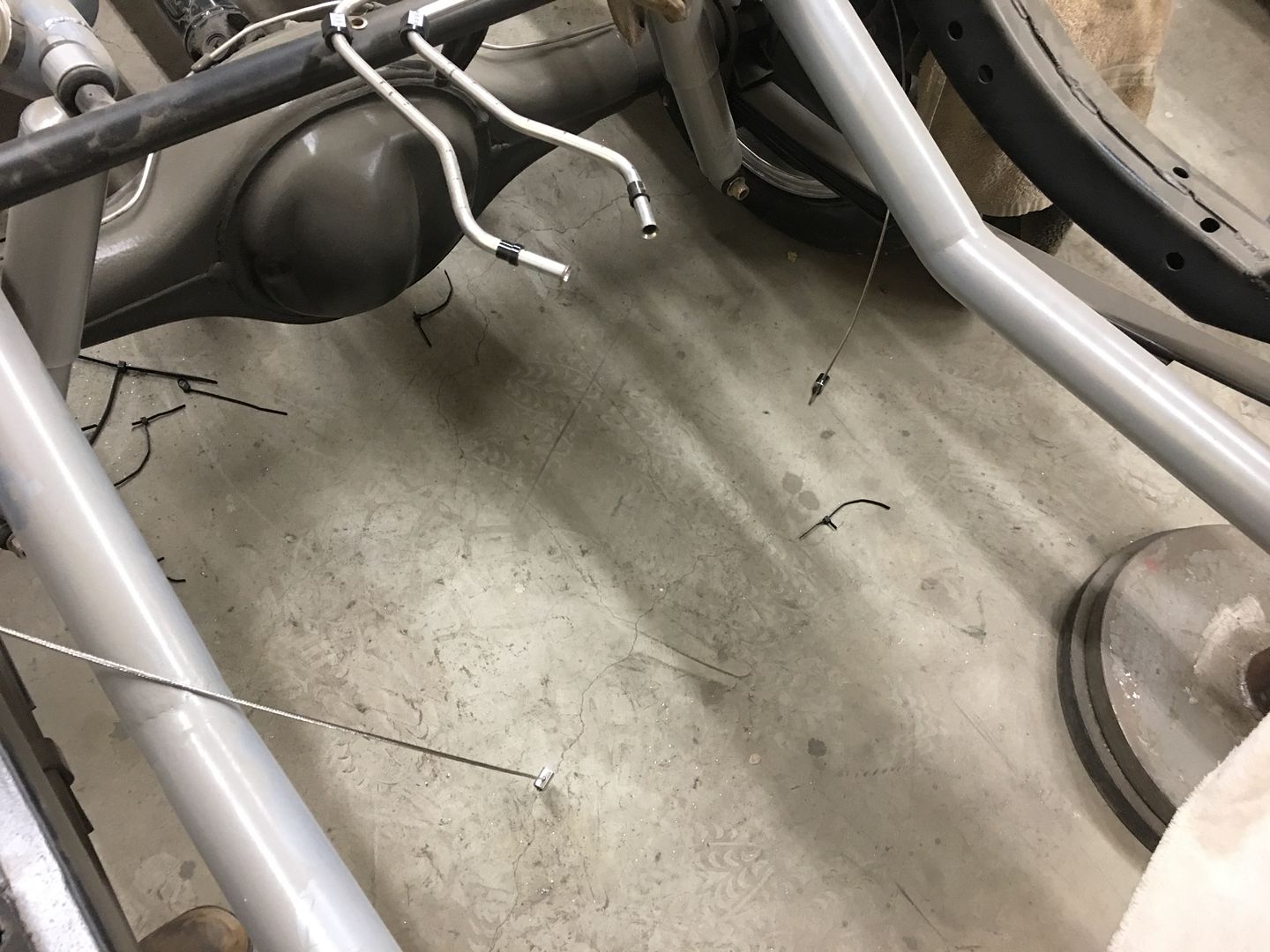
Be sure to pull cables out of the way prior to cutting...
Our implement of destruction...
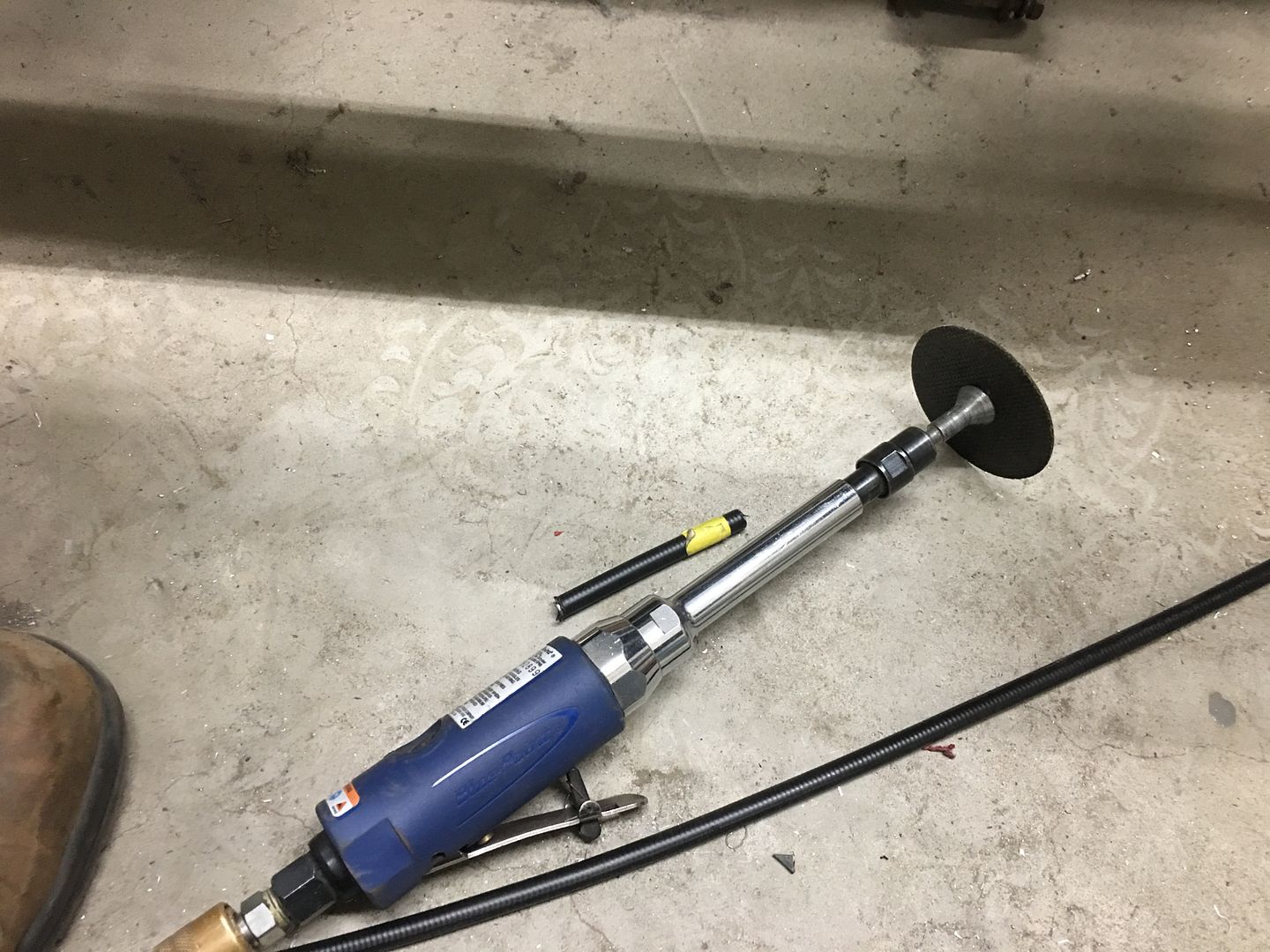
Using Gripple cutters to cut the cable... Also made by Knip-ex, both are designed for cutting steel wire rope..
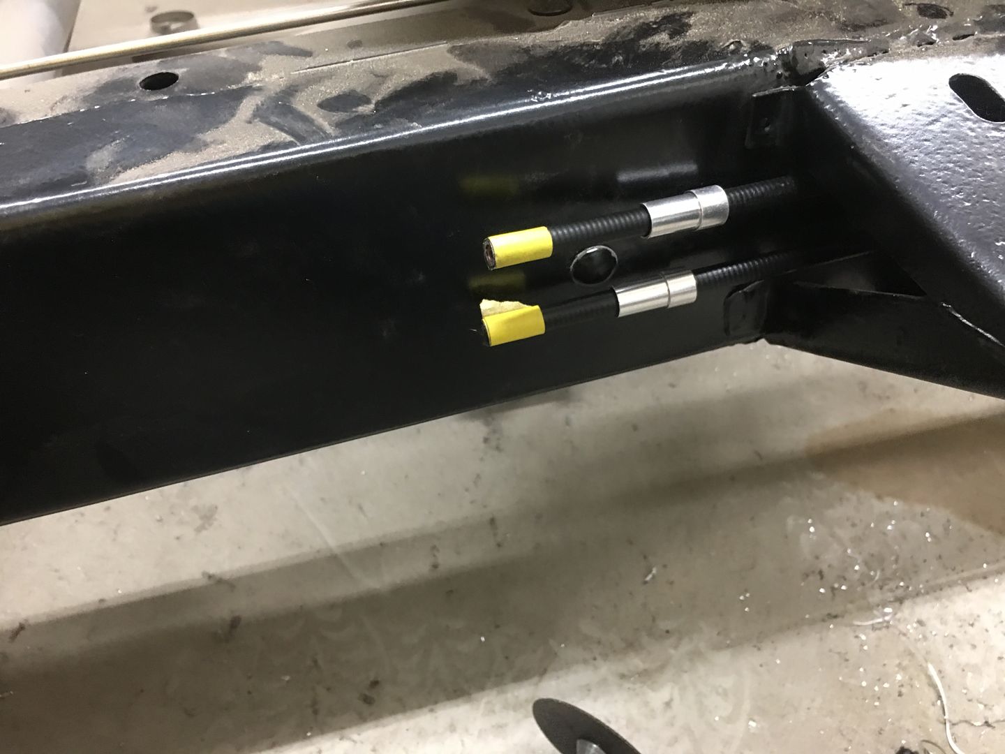
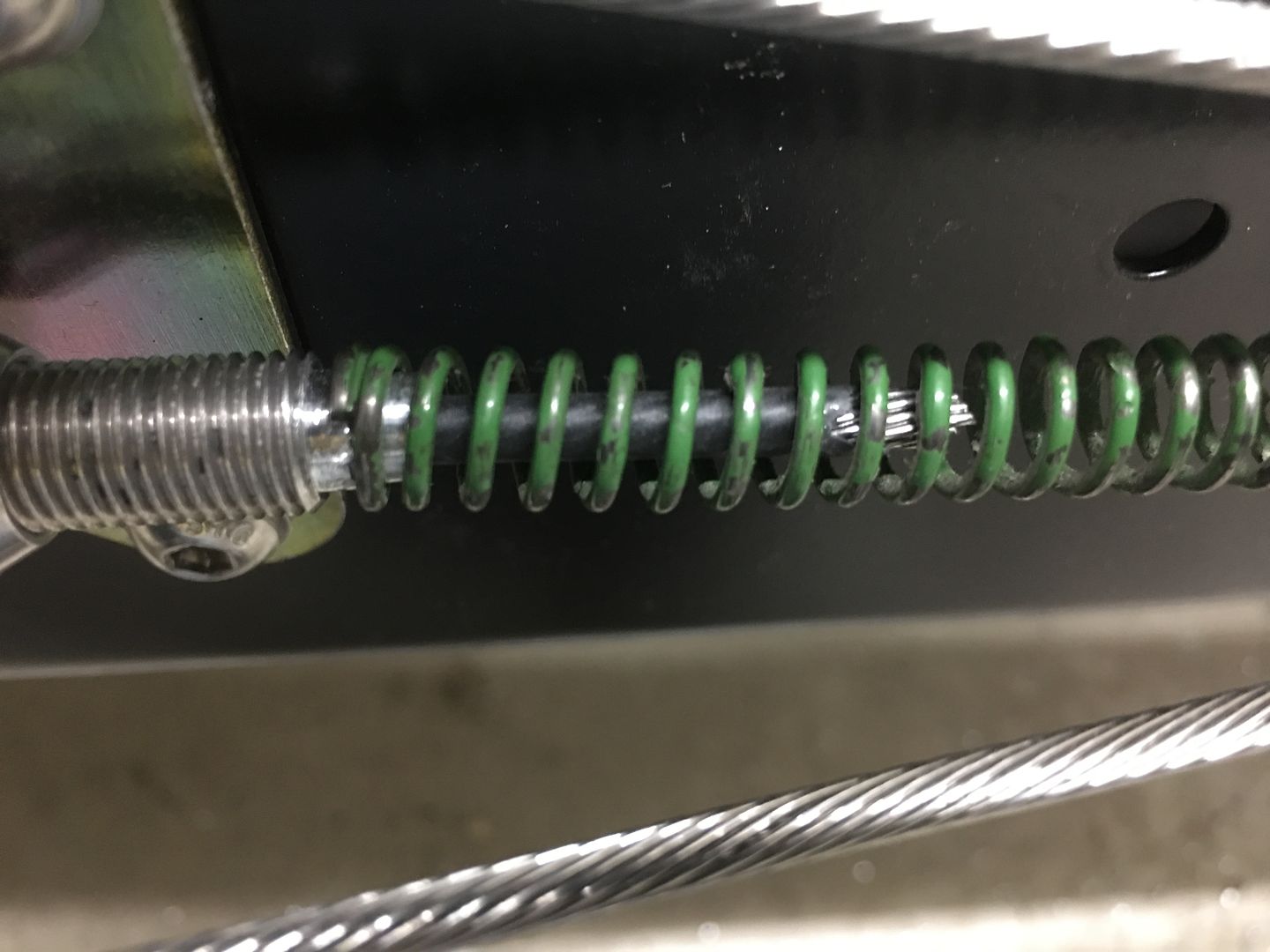
Our parking brake assembly used an integral "return spring" to pull the pedal back upwards when the brake is released, so that part is saved for this installation as well. To keep the end of the spring from rubbing against the cable in one spot, we machine a landing in the adjuster. We will also use some Teflon heat shrink over the cable to help prevent wear.
Final trim on the rear cables will come when we drop the body back on the frame for proper fitment to the brake pedal assembly.
.
I think he's having too much fun...
We had to wait for -5 clamps as these were snug enough to hold the cable from moving. This allows us to set the length to the backing plate such that it clears the frame during suspension travel..
The clamps were held in place using rivet nuts installed into the frame. Here is a video showing rivet nuts and the proper installation:
Outer sheaths are marked for trimming..
Be sure to pull cables out of the way prior to cutting...
Our implement of destruction...
Using Gripple cutters to cut the cable... Also made by Knip-ex, both are designed for cutting steel wire rope..
Our parking brake assembly used an integral "return spring" to pull the pedal back upwards when the brake is released, so that part is saved for this installation as well. To keep the end of the spring from rubbing against the cable in one spot, we machine a landing in the adjuster. We will also use some Teflon heat shrink over the cable to help prevent wear.
Final trim on the rear cables will come when we drop the body back on the frame for proper fitment to the brake pedal assembly.
.
Last edited:
shortykorte
Well-known member
I like the smiley face but looks like he’s milking the job. That will be quite the exhaust tip.
Didn’t realize parking brakes could be a work of art.
Shorty Korte
Always remember quality in QST
Sent from my iPhone using Garage Journal
Didn’t realize parking brakes could be a work of art.
Shorty Korte
Always remember quality in QST
Sent from my iPhone using Garage Journal
VOH
Well-known member
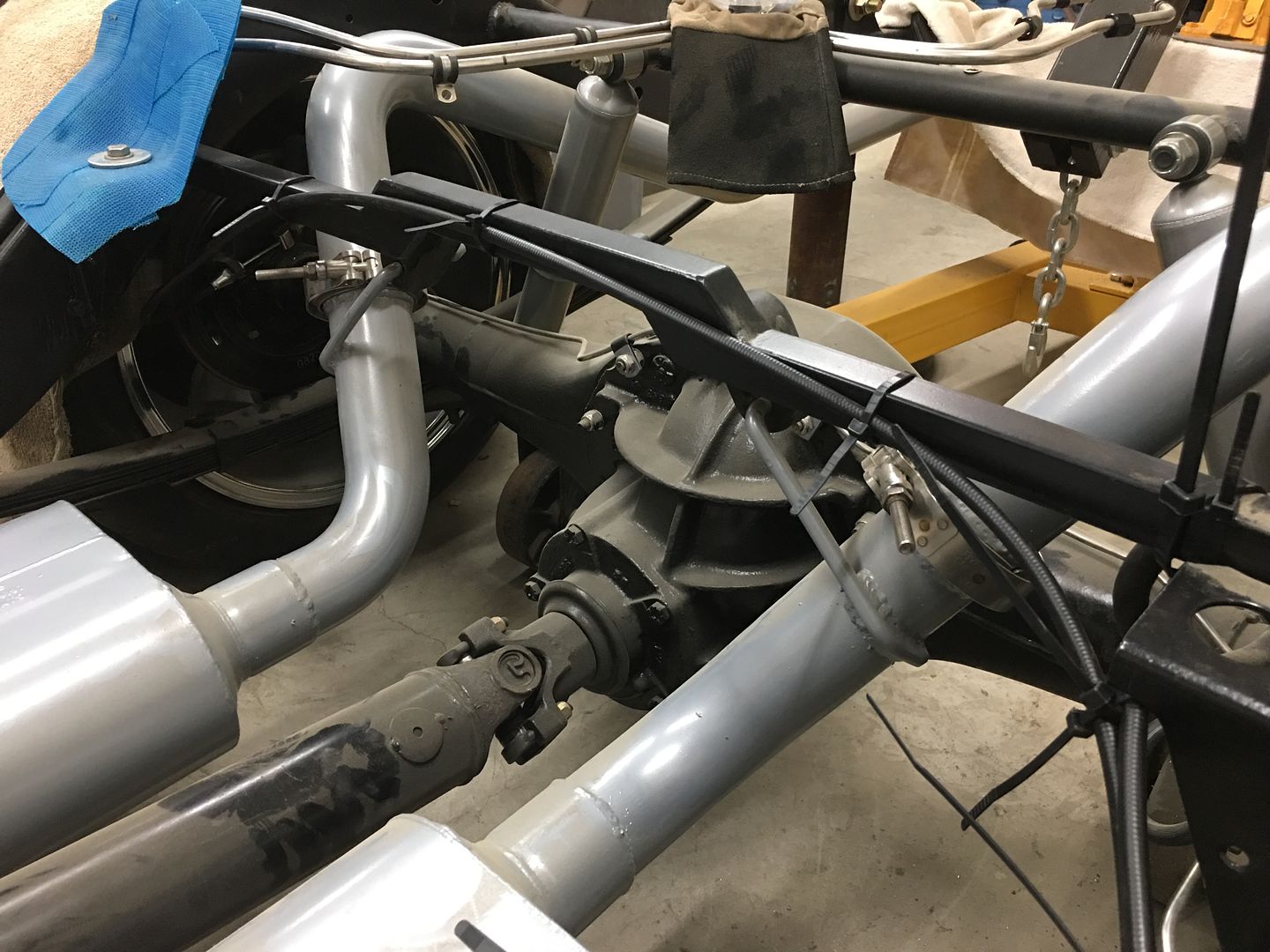
So on this setup, can you take a couple of more pics of how you get from the 2-1 point back to the axle? is the passenger setup just longer, allowing for them both to bet terminated at the common location?
I like the smiley face but looks like he’s milking the job. That will be quite the exhaust tip.
Didn’t realize parking brakes could be a work of art.
Shorty Korte
Always remember quality in QST
Sent from my iPhone using Garage Journal
I'm working with clowns over here, I tell you!

So on this setup, can you take a couple of more pics of how you get from the 2-1 point back to the axle? is the passenger setup just longer, allowing for them both to bet terminated at the common location?
Both rear cables are 8' in length, as the driver's side is more of a straight shot, it has more cut off the outer sleeve so they end up terminated at same spot..
VOH
Well-known member
Thank you sir, that makes sense. Are the rear cables specific to that rear axle or universal? It looks like Lokar.
VOH
VOH
Had a visitor in the shop yesterday, collaborating with Cody Walls of Traditional Metalcraft (Milton, DE) on adding some louvers to an Austin Healey project he has in his shop. We got the bonnet done yesterday, and I had to modify my radius fixture for the boot as it had too much crown to simply louver while flat. So that is yet to come.
Time lapse:
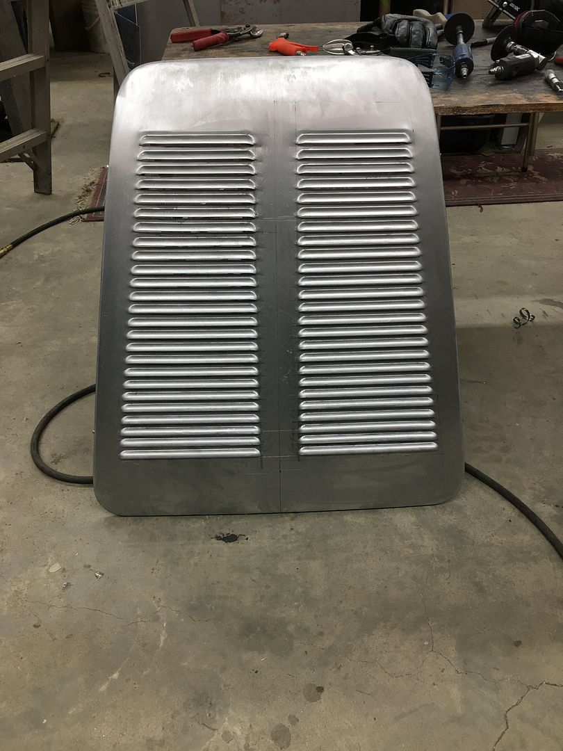
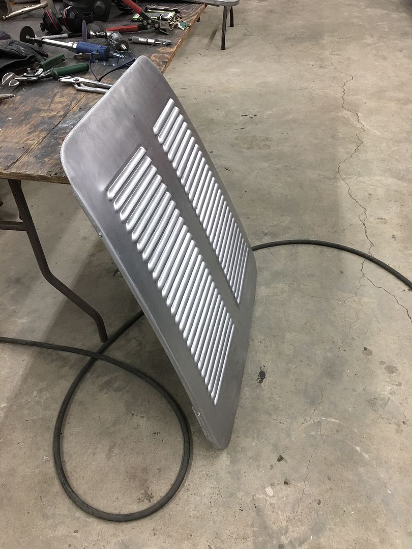
Modifying our radius fixture for louvering the boot:
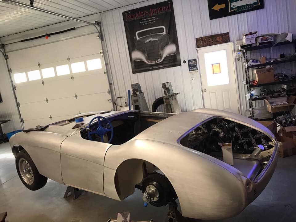
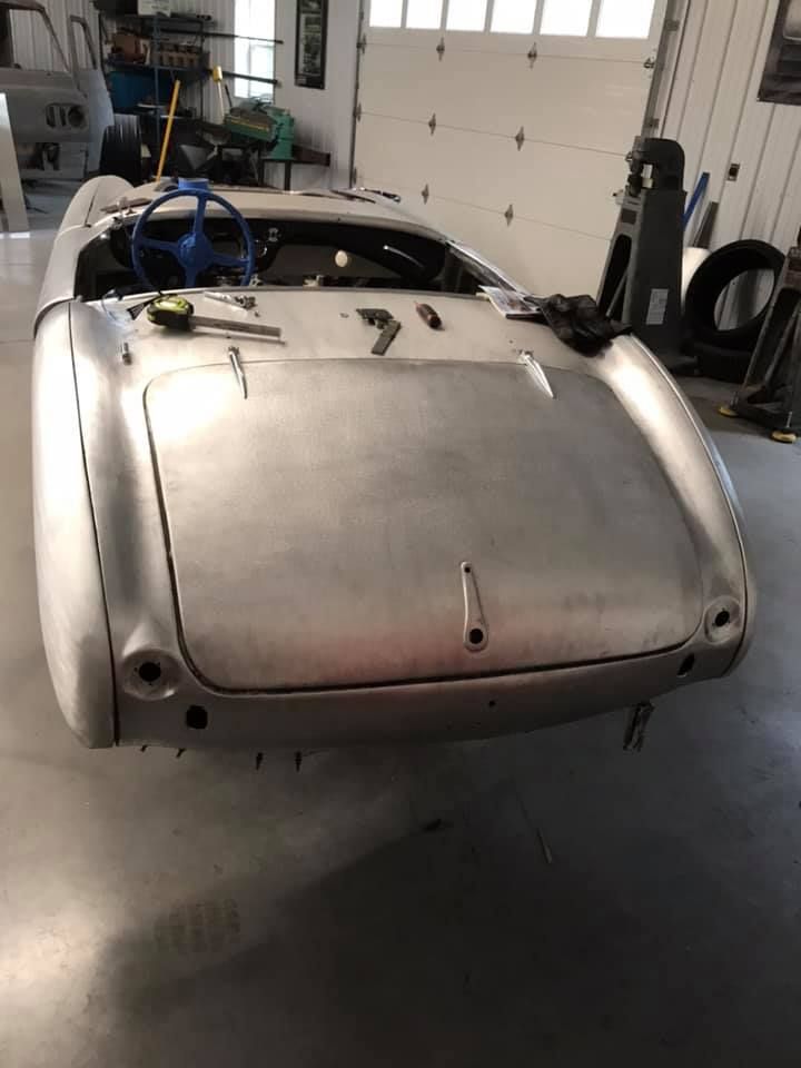
Here's pictures of the project car in Cody's shop for reference. Photo credit Traditional Metalcraft. Follow the progress on his build @eastcoastchanneljob on IG or Traditional Metalcraft on FB. This car is sporting a Honda S2000 drivetrain, should be a handful..
Time lapse:
Modifying our radius fixture for louvering the boot:
Here's pictures of the project car in Cody's shop for reference. Photo credit Traditional Metalcraft. Follow the progress on his build @eastcoastchanneljob on IG or Traditional Metalcraft on FB. This car is sporting a Honda S2000 drivetrain, should be a handful..
xtremek
Well-known member
Holy cow.
Stuart in MN
Well-known member
Cody Walls does incredible work. He has some picture threads over on the HAMB that are well worth looking at.
Bowtie4life
Well-known member
Very nice work Robert!!!
stinkity stoink
Well-known member
Wow !!! I got nothing else, I’m constantly impressed
jimkinney
Well-known member
Wow !!! I got nothing else, I’m constantly impressed
Ditto!
From the time lapse video, it looks like you need some automation
 , lots of up-down going on.
Great job.
shortykorte
Well-known member
Ditto!
From the time lapse video, it looks like you need some automation
Great job.
I was wondering how they achieved such straight lines while working that fast.

Shorty Korte
Always remember quality in QST
Sent from my iPhone using Garage Journal
Chateau Slate 66
Well-known member
That video answers the question "why are my legs sore? I just stood around all day." ")
Thanks for the comments guys..
Before we added the multi-position adjuster on the Lennox, all the tooling height adjustments would have been changed using the jack screw at the bottom. So with four passes for each louver, 4 adjustments, or four times each louver kneeling down to adjust the jack screw. With this new feature, one adjustment when changing location to a new louver, and all the rest are handled by this new addition to the machine.

The worst was the 100 louvers we did when Cody came by with the 35 Chevy hood sides. Yes, that was 400 times up and down to change settings. I could hardly walk the next day, legs sore for a week. So definitely glad we have the new adjuster this time around.
Vince is still milking the media blast job..
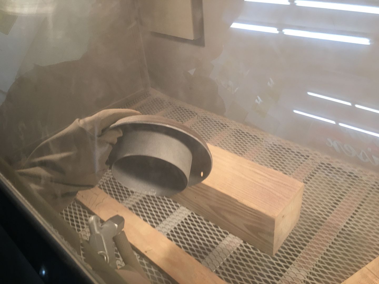
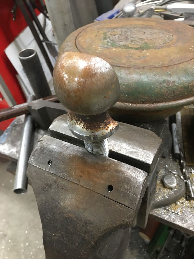
Another of the lids had been used and abused with a hammer over it's life, the center was concaved inward, the outer rim had several flat spots. So while Vince was busy, I came up with a dent removal tool to help straighten out the next lid.
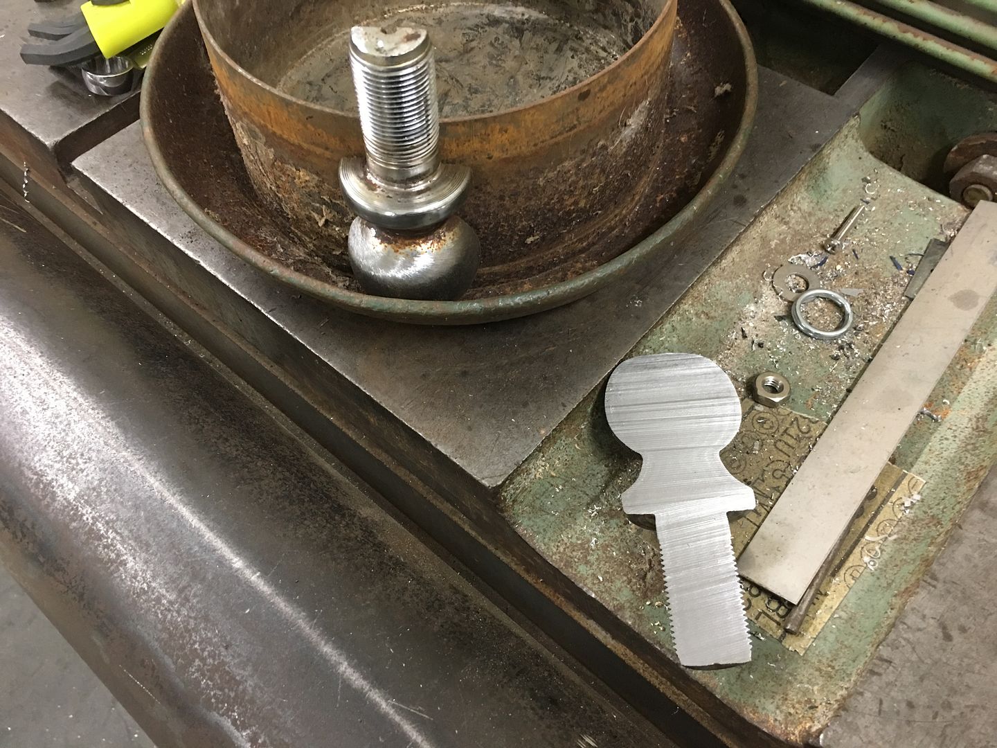

The half hitch ball was used as a punch straight down into the lid to add a consistent shape back to the outer ring. Some hammer and dolly work straightened the center concave, giving it a slight crown. A deep dent was heated to make it more pliable, the punch pushed to the bottom and used as fulcrum to push the dent outward (heated spot)
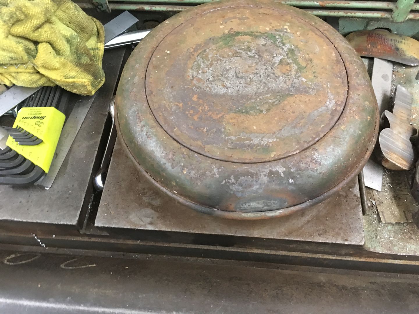
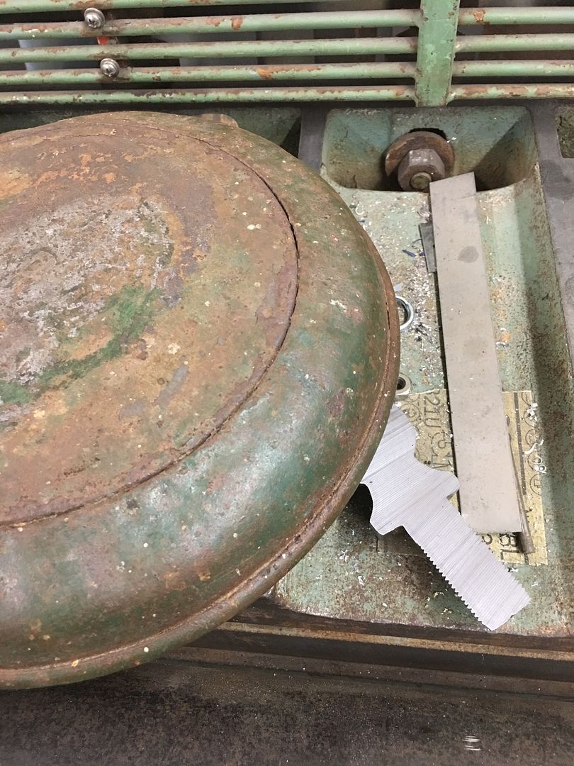
Then our "punch" was clamped in the vise to use as a post dolly. The lid was positioned where any low spots were placed against the "dolly" and hammering around the perimeter of the dent raised it outwards..
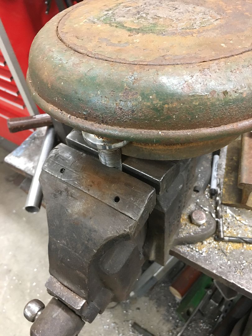
Some fine tuning left, but this is much better than where we started:
.
Before we added the multi-position adjuster on the Lennox, all the tooling height adjustments would have been changed using the jack screw at the bottom. So with four passes for each louver, 4 adjustments, or four times each louver kneeling down to adjust the jack screw. With this new feature, one adjustment when changing location to a new louver, and all the rest are handled by this new addition to the machine.
The worst was the 100 louvers we did when Cody came by with the 35 Chevy hood sides. Yes, that was 400 times up and down to change settings. I could hardly walk the next day, legs sore for a week. So definitely glad we have the new adjuster this time around.
Vince is still milking the media blast job..
Another of the lids had been used and abused with a hammer over it's life, the center was concaved inward, the outer rim had several flat spots. So while Vince was busy, I came up with a dent removal tool to help straighten out the next lid.
The half hitch ball was used as a punch straight down into the lid to add a consistent shape back to the outer ring. Some hammer and dolly work straightened the center concave, giving it a slight crown. A deep dent was heated to make it more pliable, the punch pushed to the bottom and used as fulcrum to push the dent outward (heated spot)
Then our "punch" was clamped in the vise to use as a post dolly. The lid was positioned where any low spots were placed against the "dolly" and hammering around the perimeter of the dent raised it outwards..
Some fine tuning left, but this is much better than where we started:
.
Last edited:
Bob Heine
ALLIANCE MEMBER
Robert, all those customized Vise-Grips you made and used over the years were cool but the Half-Hitch dolly is over the top. Thanks for reminding me to see beyond the standard tool box.
Ohmthis
Well-known member
I was going to say “everything is a tool”, but you take it to the top.
xtremek
Well-known member
So the biggest take-away I have from all of this is I need to stop being so tight with my resources.
joe49
Well-known member
on the tow ball, yes everything is a tool just waiting for someone to see it's use.I didn't use adhesive The inner door has a bit of twist available when skin is "unsecured". So the inner and outer parts were epoxy primed separately, inner installed back on the car, then skin wrapped. Then you can twist the door to better match the opening. Some plug weld holes were drilled from the back side in the flange, and welded in place to hold the door skin in place, and lock the "twist". Plug welds then cleaned up and epoxy primed. Poured some epoxy primer around the inside perimeter to seal up the seam.
Last edited:
Some equipment maintenance, my Watervliet planishing hammer has always had some issues getting started. You'd hear air blowby, and would have to bump the hammer to get it started. Pulling the piston apart, there was a noticeable scratch...
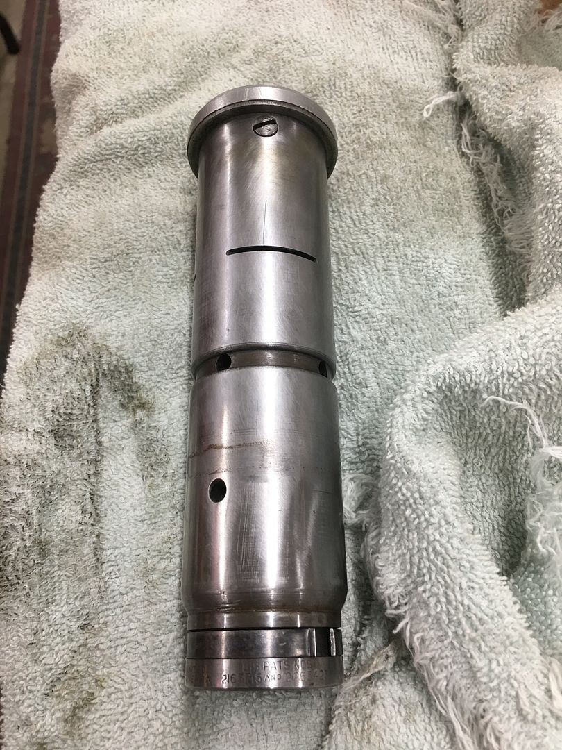
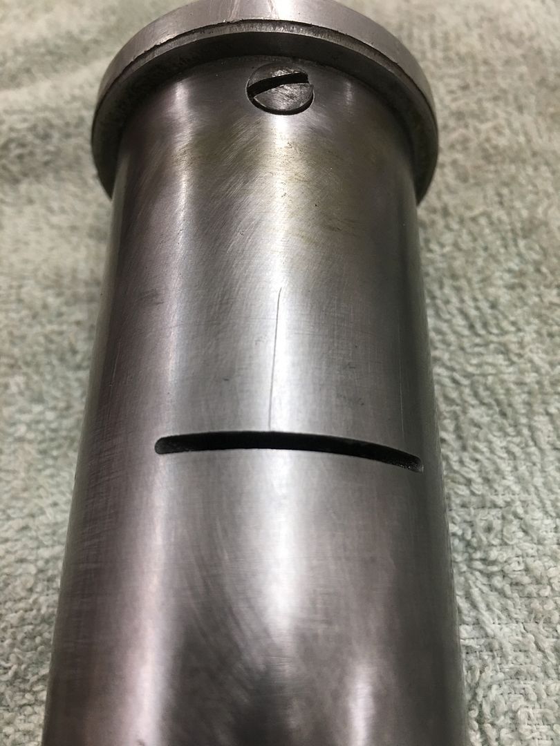
So it was chucked up in the lathe and turned until the scratch removed.
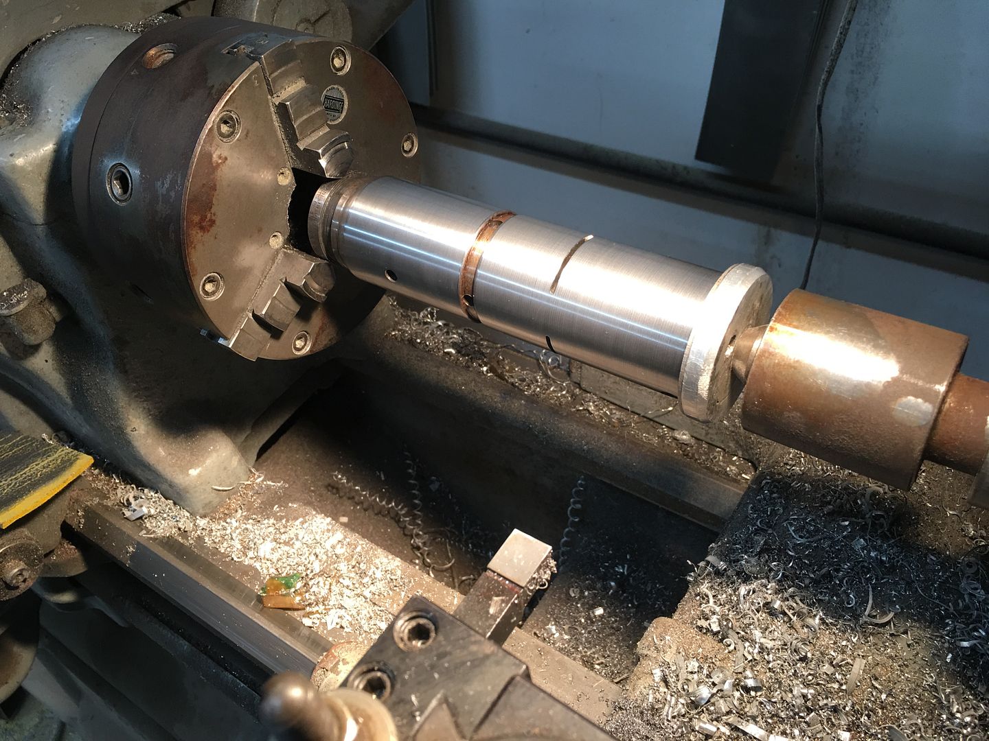
Everything reinstalled with new O-rings from Renato Muskovic in Vancouver, and it's now functioning as it should..

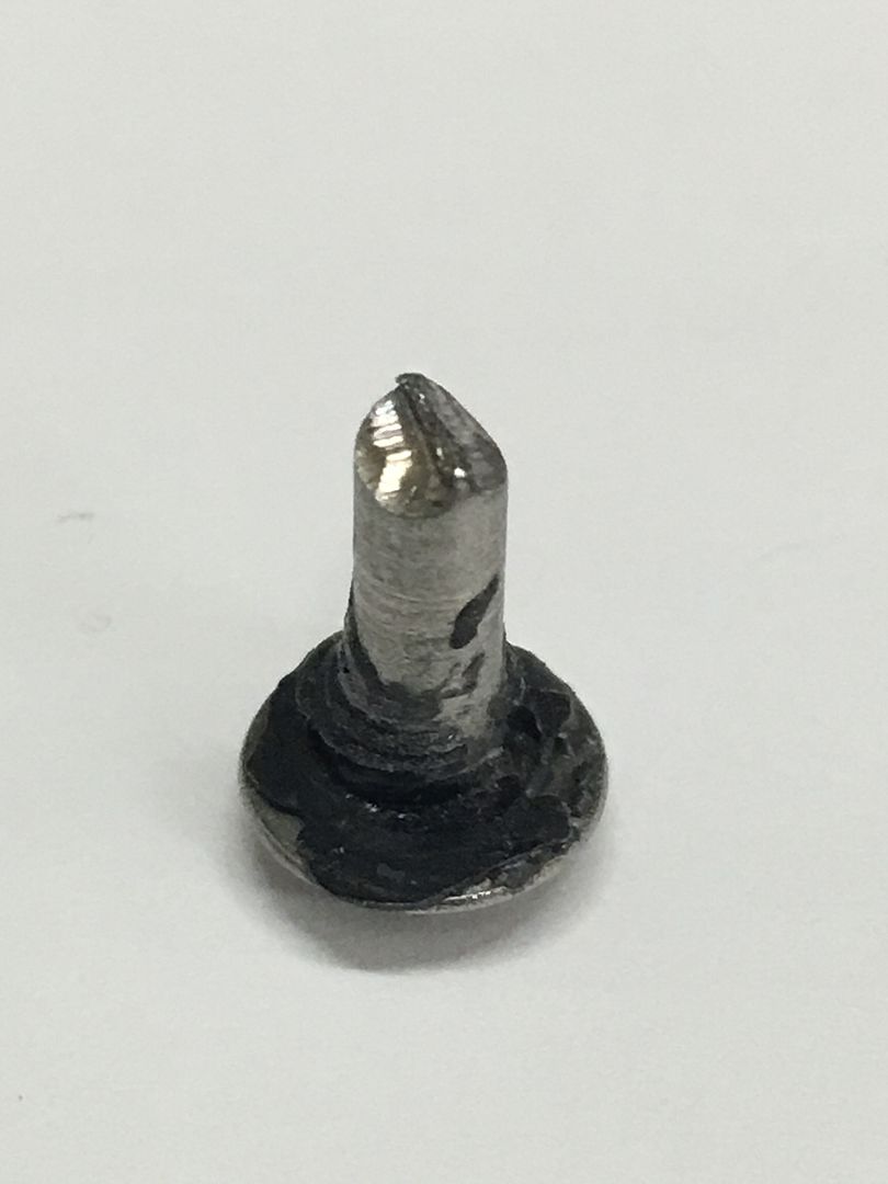
On another lathe job, we needed to make some captive screws to match some existing. We had a "refurbished" piece of equipment that had mis-matched hardware as they just put something in the hole. Note the 8-32 captive screw and the 6-32 screws used as filler, one with epoxy to hold it in place.
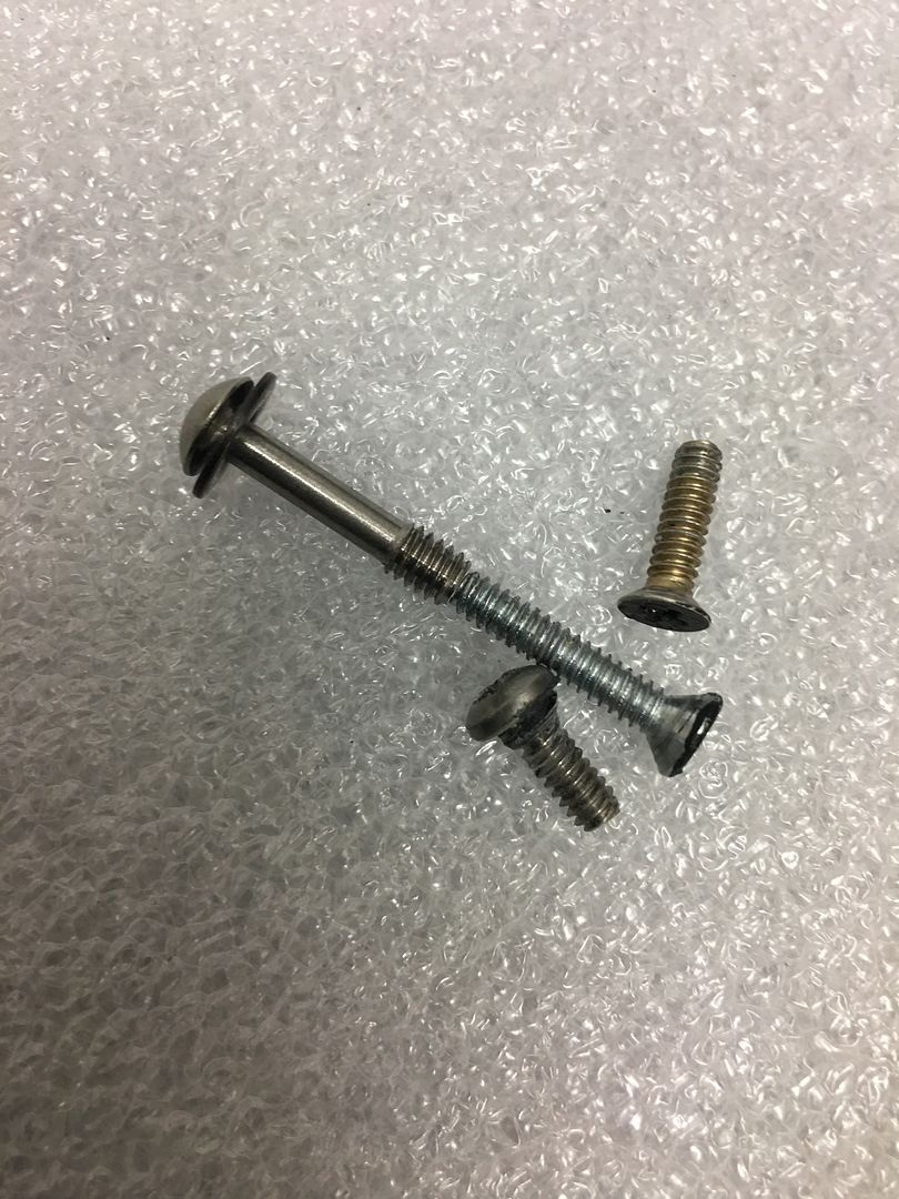
We found another screw that had been wrung off, so they trimmed the remaining piece off to fit better, and epoxied this in the hole....
With all the strays removed, now to make our replacements. My go to supplier, McMaster failed me in that they only had Phillips head captive screws. So we ordered the socket drive screws fully threaded so we could make our own to match originals..
Added our "surface grinder" to the Aloris tool holder..
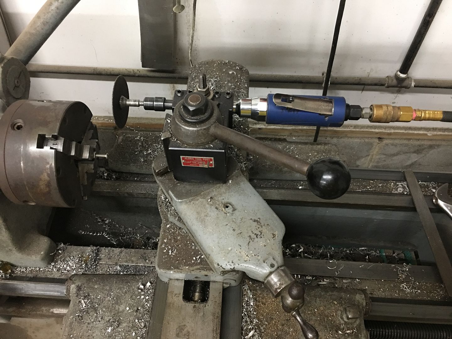
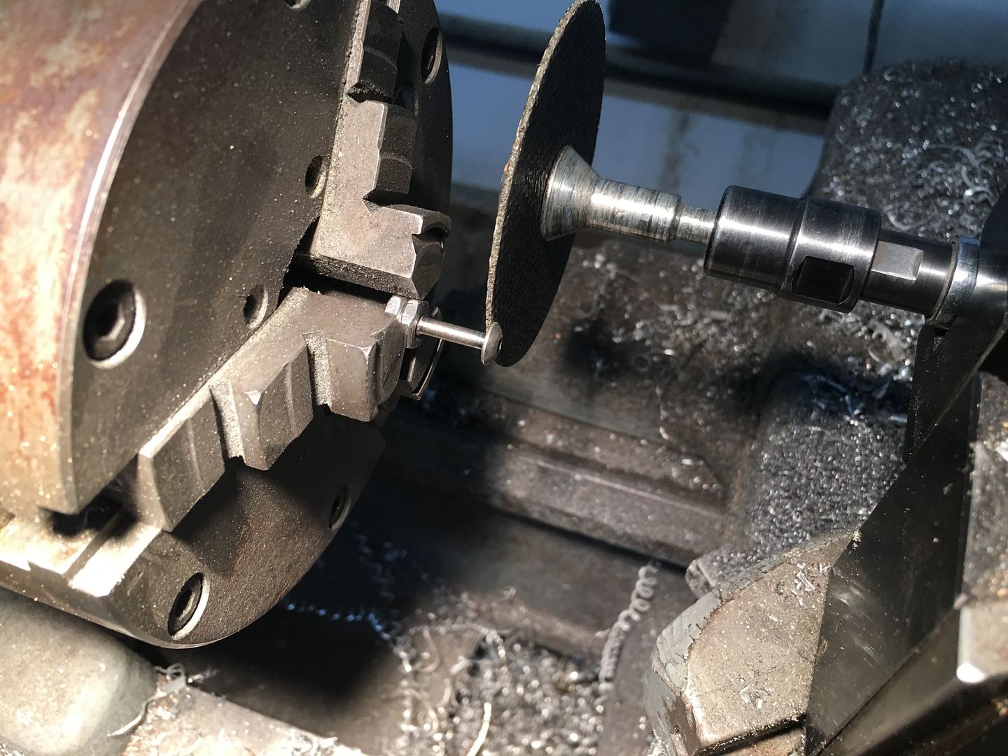
Finished product....
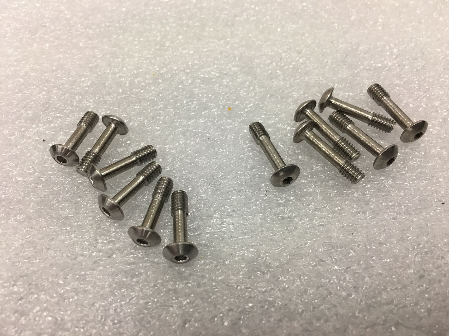
Yeah, we work on just about anything..
So it was chucked up in the lathe and turned until the scratch removed.
Everything reinstalled with new O-rings from Renato Muskovic in Vancouver, and it's now functioning as it should..
On another lathe job, we needed to make some captive screws to match some existing. We had a "refurbished" piece of equipment that had mis-matched hardware as they just put something in the hole. Note the 8-32 captive screw and the 6-32 screws used as filler, one with epoxy to hold it in place.
We found another screw that had been wrung off, so they trimmed the remaining piece off to fit better, and epoxied this in the hole....
With all the strays removed, now to make our replacements. My go to supplier, McMaster failed me in that they only had Phillips head captive screws. So we ordered the socket drive screws fully threaded so we could make our own to match originals..
Added our "surface grinder" to the Aloris tool holder..
Finished product....
Yeah, we work on just about anything..