To avoid these ads, REGISTER NOW!

My IR SS5 air compressor

alan camby

Well-known member
Joined
Dec 3, 2011
Messages
1,566
Location
South of Indianapolis, Indiana
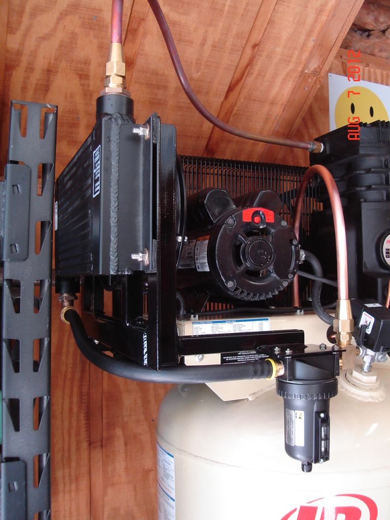
I have a Ingersoll Rand 80 gal SS5 air compressor. I was just making this thread to document the modifications to my unit. I don't really have any questions to start out with but feel free to comment and question my compressor modifications.
The other reason I started this thread is because I am starting to go off topic on the after cooler thread http://garagejournal.com/forum/showthread.php?t=50946&page=8 and did not want to hijack that thread.

The pump (SS5) is a single stage in line 2 cylinder pump that turns at approximately 1000 rpm. The compressor label shows a CFM of 18.1 at 90psi.

The drive motor is a single phase Emerson 5hp pulling 22.5 amps at 230volt.

Anyhow I am working on cooling the air in order to get the moisture to fall out before the water can make it to the air lines.

Here is where i am at in the after cooler thread.
aftercooler3008.jpg

aftercooler3011.jpg

below is what i wrote about the cooler in the aftercooler thread.
"Here is the temperatures I came up with this time.

The temp in my garage was 90 degrees F.

Started the test with a full tank of air.
Unhooked the sand feed line in the blast cabinet and put a bucket on the foot air valve, just like i did the last time. pressure stayed around 90-95 the entire test and the compressor ran 100% of the time. All temps are in Fahrenheit. All temps are the highest recorded for the area tested. Temps are surface temps.

One minute of running
198.9 degrees at the inlet of the cooler
98.8 degrees at the outlet of the cooler
96 degrees at the inlet of the tank check valve

six minutes
285 degrees at the inlet of the cooler
111.2 degrees at the outlet of cooler
103 degrees at tank check valve
Also checked the compressor pump head temp. at 331 degrees

ten minutes
305 degrees inlet of cooler
111.9 outlet of cooler
107 degrees at tank check valve.
356 degrees head temp.

outlet of the water trap just felt warm to the touch. Could easily hold onto it for as long as i wanted. Cooler then the temperature of the water i wash my hands with. I would never intentionally touch that pump outlet pipe"


My next project is to cool the pump on the compressor in order to get a lower outlet temperature and increase pump life.
I am doing some testing to prove that this is reducing my temperatures.

Here is the how i rigged up a muffin fan (equipment cooling fan) to cool the head.
Note: this is a temporary mount for testing.
compheadcooling002.jpg


here you can see the stock belt drive flywheel fan and how none of the air is directed to the top of the pump. I think this is a design flaw, and should have had a shroud to direct more air to the head.
compheadcooling001.jpg


Now i don't have time to write this entire thread today. I plan to add part #'s for the items i used and where i got them, a bunch of pictures, and all my other modifications. this will take weeks if not months for me to slowly complete
Thanks for looking
 
Last edited:
To avoid these ads, REGISTER NOW!

EOC_Jason

Well-known member
Joined
Jun 25, 2012
Messages
11,388
Location
Bentonville, AR
Subscribed!

I wouldn't exactly call the smaller flywheel a design flaw, I would just call the company being cheap. They shrink the flywheel to up the pump RPM. However on the flip side the more pump RPM = more heat... But again they don't want these to last forever because they want to keep selling you repair kits and new compressors! ;)

I burnt my hand pretty good on a big compressor that had 3/4" piping... Common sense would of said don't touch that when you see the copper is so hot that it's slightly discolored... lol...
 
OP
A

alan camby

Well-known member
Joined
Dec 3, 2011
Messages
1,566
Location
South of Indianapolis, Indiana
Here are the results for the fan mounted on a board, this is temporary remember:D. the idea is to cool the head of the pump.

Very hot today, around 95 degrees outside.

One Minute after running the compressor with the fan cooling the pump head.
156 degrees F inlet of aftercooler
92.8 outlet of aftercooler
89 degrees inlet of tank at check valve
177 pump head temp

Six minutes of running.
273 degrees inlet of after cooler
111.8 degrees outlet of after cooler
98 degrees inlet of tank
293 pump head temp

Ten minutes of running
287 inlet of aftercooler
112.4 outlet of after cooler
98 inlet of tank
311 head temp.

Summary of adding a fan on the head of the pump.
The head temperature has gone down by 45 degrees after 10 min and 38 degrees after 6 minutes.
While the other temperatures have stayed about the same.
 
OP
A

alan camby

Well-known member
Joined
Dec 3, 2011
Messages
1,566
Location
South of Indianapolis, Indiana
Subscribed!

I wouldn't exactly call the smaller flywheel a design flaw, I would just call the company being cheap. They shrink the flywheel to up the pump RPM. However on the flip side the more pump RPM = more heat... But again they don't want these to last forever because they want to keep selling you repair kits and new compressors! ;)

I burnt my hand pretty good on a big compressor that had 3/4" piping... Common sense would of said don't touch that when you see the copper is so hot that it's slightly discolored... lol...

ha ha, they (IR) won't be selling me a new pump. I will go 2 stage(diff brand) if this pump fails.
 
Last edited:

pipsters

Well-known member
Joined
Sep 1, 2010
Messages
4,899
Location
USA
It looks as though keeping the head cooler is also reducing the temps going into the tank. Makes sense when you think about it.

So, question is does a 45* temp drop affect long term pump life? IIRC that pump is rated for 15,000 hours. That is a really long time to begin with.
 

PT Doc

Well-known member
Joined
Nov 12, 2010
Messages
3,197
I think that the purpose of the fan is to keep everything add cool add possible and not try to extend the pump life. That might be one benefit though. Would be weird if cooling the pump was actually somehow detrimental. I don't think so but this is not my area of expertise.
 
OP
A

alan camby

Well-known member
Joined
Dec 3, 2011
Messages
1,566
Location
South of Indianapolis, Indiana
here is what i have so far, It is not done yet. Still want to add a shroud for this side of the compressor so that the flywheel fan will cool the side of the pump. The other side of the pump will be left alone so that the air can cool the drive motor also.


Here I installed some longer 3/8" bolts upside down so that i could utilize the studs on top.
compheadfan001.jpg


Here is the base that i cut out of angle steel.
compheadfan004.jpg


More pics soon
 
OP
A

alan camby

Well-known member
Joined
Dec 3, 2011
Messages
1,566
Location
South of Indianapolis, Indiana
mounts like this. Trying to stay away from drilling any more holes then I have to in the comp main frame.
compheadfan005.jpg


compheadfan007.jpg


compheadfan009.jpg


the fan mount is spaced about 1/2" from the head fins, and the mount spaces the fan 1/8" higher. So the gap is about 5/8".
 
Last edited:

pipsters

Well-known member
Joined
Sep 1, 2010
Messages
4,899
Location
USA
Those welds look so smooth, almost like it was JB Weld! Nice job. How are you cutting the metal? Do you do metal fab for a living?
 
OP
A

alan camby

Well-known member
Joined
Dec 3, 2011
Messages
1,566
Location
South of Indianapolis, Indiana
No, I sell maintenance supplies with my dad. I worked in a factory for 12.5 years in maintenance though. No JB weld.......yet. Building stuff is my hobby.

I cut this metal with a Rage II. I just bought the thing when Lowes was getting rid of them for $107. The more intricate cuts are made with a 4.5" angle grinder. I just drill a hole where I want the corners and cut the rest with the AG.

thanks
 
OP
A

alan camby

Well-known member
Joined
Dec 3, 2011
Messages
1,566
Location
South of Indianapolis, Indiana
Here is the shroud I am working on. Hoping this will divert some of the wasted air back to the pump. It is made out of 14 gauge stainless so it will not be painted. Every other metal piece I made tonight will be painted black.

compshroud004.jpg


compshroud002.jpg
 

bsaint

Well-known member
Joined
Apr 26, 2010
Messages
5,109
Location
Manchester, CT
Most off the shelf piston compressors with aftercoolers mount them in front of the flywheel so that you don't loose efficiency with the compressor. If you gain a certain amount of CFM, that gain is offset by the power consumption of a stand alone fan cooled aftercooler. Another idea is mounting a fan on the motor in front of the pulley.

Your setup looks good!
 
OP
A

alan camby

Well-known member
Joined
Dec 3, 2011
Messages
1,566
Location
South of Indianapolis, Indiana
Most off the shelf piston compressors with aftercoolers mount them in front of the flywheel so that you don't loose efficiency with the compressor. If you gain a certain amount of CFM, that gain is offset by the power consumption of a stand alone fan cooled aftercooler. Another idea is mounting a fan on the motor in front of the pulley.

Your setup looks good!

I thought about mounting mine in front of the flywheel but I am not getting much airflow with the flywheel like i am with the electric fan. Not only that but if it is in front of the flywheel the compressor has hot air blowing over the pump. That seems like lost efficiency to me. My fan only pulls .24 amps at 230 VAC. So I don't think that is a big deal.
 
OP
A

alan camby

Well-known member
Joined
Dec 3, 2011
Messages
1,566
Location
South of Indianapolis, Indiana
Installed my freshly painted air shroud tonight. I am not going to put the fan up there until I am ready to run the wiring.

shroudforcomp007.jpg


shroudforcomp005.jpg


The shroud seems to work well. I am getting air flow all the way around the sides were ther used to be no flow.
 

PT Doc

Well-known member
Joined
Nov 12, 2010
Messages
3,197
Looks like things are working out well.

Could you have used 90* fittings to make the copper routing easier? What tpe of Jose from the cooler to te water separator? Could that be used from the separator to the tank instead of copper?
 
To avoid these ads, REGISTER NOW!
OP
A

alan camby

Well-known member
Joined
Dec 3, 2011
Messages
1,566
Location
South of Indianapolis, Indiana
Doc, all is coming together as planned.
I could have used more 90* fittings but I feel they are a restriction. I think that a gradual bend would have less internal friction then a sudden 90* and that is why I chose the method I did. The hose is something I am a huge fan of. It is called "push lock" or "push on hose". I get some of the fittings at Mcmaster-Carr and some from my dad at Kimball Midwest.

This is what I am talking about http://www.fastfittings.com/push-on-hose-barb

I have never bought from the linked company but they seem to have a good selection of odd fittings, their prices are very high. I thought about using the push on hose from the separator to the tank but did not haver one of these http://www.fastfittings.com/product/30286 my check valve has the odd inverted flare fitting.

I have installed hundreds of these push on hoses and have never seen one come off or leak. I think they are the cats meow. Much cheaper than hydraulic hose and much more flexible. The 300psi hose that Mcmaster-Carr sells has always showed up as Thermoid brand. I have used Goodyear and Parker hose also with good results.

Thanks for stopping by my thread.
 
Last edited:
OP
A

alan camby

Well-known member
Joined
Dec 3, 2011
Messages
1,566
Location
South of Indianapolis, Indiana
Started working on the motor starter and fan control box today. I was lucky and found a nice industrial 14 gauge junction box in the barn.

Here is the lower mount that will attach to my compressor base. It is made out of some 2"x4" c channel and 1.75" tube with a wall thickness of .125"
starterbox001.jpg

starterbox002.jpg


Here it is attached to the frame with two 1/2-13 bolts.
starterbox006.jpg


I welded some 3/16" 1.5x1.5" angle to the back of the box to reinforce the connection point. The box will connect to the tube with two 3/8-16 bolts.
starterbox008.jpg

starterbox007.jpg

This is the completed mock up. Now I need to strip all the paint off the J box and finish a few welds on the top of the tube. Think i will paint the box gray and the tube black.
starterbox004.jpg


Thanks for looking:)
 
OP
A

alan camby

Well-known member
Joined
Dec 3, 2011
Messages
1,566
Location
South of Indianapolis, Indiana
Finished the support tube for the starter box and painted it. Thought i would add a brace to stabilize the tube a little and add some cool factor.

Cut the brace out of this scrap steel.
pressureswitchandstartertube001.jpg


pressureswitchandstartertube009.jpg


pressureswitchandstartertube012.jpg
 

PT Doc

Well-known member
Joined
Nov 12, 2010
Messages
3,197
Black Hammer tone.

Do you the technics specs on the cooler you used? Size, weight, max intake temp, output temp, max psi, max scfm, input/output pipe size. Thanks
 

roblouvasz

Well-known member
Joined
Nov 12, 2011
Messages
1,314
Location
Somewhere between the end of the line and the midd
Do you have a magnetic starter on this? Or are you running the line voltage for the motor through the pressure switch to the motor. If so, your motor is eventually going to burn up due to the fact that the contacts in the pressure switch are not really made to handle that kind of current. My IR 5hp 80gal. motor burned up after only 2 years of use. I replaced the motor with one from Grainger and installed a magnetic started. And for what's it worth, check ALL the bolts on the pump! Mine were loose! A friend of mine got the same compressor and his flew apart! Luckily no one was near it. Good luck.
 
OP
A

alan camby

Well-known member
Joined
Dec 3, 2011
Messages
1,566
Location
South of Indianapolis, Indiana
Do you have a magnetic starter on this? Or are you running the line voltage for the motor through the pressure switch to the motor. If so, your motor is eventually going to burn up due to the fact that the contacts in the pressure switch are not really made to handle that kind of current. My IR 5hp 80gal. motor burned up after only 2 years of use. I replaced the motor with one from Grainger and installed a magnetic started. And for what's it worth, check ALL the bolts on the pump! Mine were loose! A friend of mine got the same compressor and his flew apart! Luckily no one was near it. Good luck.

I am adding the starter now. That is what the electrical box is for. I am on my second PS. Soon the PS will live the easy life when the Starter takes over the high current job. I know these motors have a bad track record and some have caught fire.
 
OP
A

alan camby

Well-known member
Joined
Dec 3, 2011
Messages
1,566
Location
South of Indianapolis, Indiana
Black Hammer tone.

Do you the technics specs on the cooler you used? Size, weight, max intake temp, output temp, max psi, max scfm, input/output pipe size. Thanks

Post 133 here http://garagejournal.com/forum/showthread.php?t=50946&page=7

It is made by AKG# C-70100BG I think they have a spec sheet on the AKG site. I saw the info somewhere and printed it off of a PDF. Know it is 100cfm, 250psi, with a max of 400*F

The paint is Kimball Midwest Ultra pro max 80-881 gloss black. The wet paint and flash make it look textured.
 

KinzeMech

Well-known member
Joined
Jul 15, 2012
Messages
1,164
The hose is something I am a huge fan of. It is called "push lock" or "push on hose". I get some of the fittings at Mcmaster-Carr and some from my dad at Kimball Midwest.

Looks like the Eaton Weatherhead hose I get at Napa. Great stuff. My mechanic says in the 15 years he's used it at his shop, he's never thrown any length away, just put in mending splices where something has cut the hose.

The only thing I wonder about is how that hose would handle the temperature if you were to have an intercooler fan failure. That might be the weak link, although a cooling fan failure is an admittedly rare thing to occur.
 

Chadwilliam1

Well-known member
Joined
May 13, 2012
Messages
2,788
Location
Cincinnati
I plan to read this whole thread when I am on my laptop and not my cell phone.

I own the same compressor for two years now. mine blew a head gasket three months ago. IR said it was because the head bolts stretched and allowed air flow between the cylinders and killed the head gasket. IR told me to retorque the head bolts to 23 ft lbs every month or so.
 
OP
A

alan camby

Well-known member
Joined
Dec 3, 2011
Messages
1,566
Location
South of Indianapolis, Indiana
finished the starter panel today. From the panel I can turn on and off the compressor auto run (running starter off of pressure switch).

I can also control the fans to run in auto or I can force them on. Most of the time the fans will remain in auto. If I am going to run the compressor for a extended time, sand blasting, i can force the fans on so they will help cool the compressor and cooler between cycles.

compstarter002.jpg


Exclusive insiders look :)
compstarter003.jpg
 

PT Doc

Well-known member
Joined
Nov 12, 2010
Messages
3,197
Looks great. Keeps us posted and run some numbers again when you are working it hard.

Is it safe to assume that the temp of the air in a copper tube is equal to the temp of the copper tube. I'm working on something similar and am curious.

Thanks
 
OP
A

alan camby

Well-known member
Joined
Dec 3, 2011
Messages
1,566
Location
South of Indianapolis, Indiana
Looks great. Keeps us posted and run some numbers again when you are working it hard.

Is it safe to assume that the temp of the air in a copper tube is equal to the temp of the copper tube. I'm working on something similar and am curious.

Thanks

I think the temp would be very close. I have scanned steel pipe that has a temperature well sensor installed and had matching reading from the well gauge to the handheld infrared on the exterior of the pipe. I think the hardest part of scanning my copper tube is the small diameter. Have to get really close or the gun will average in some of the background temps. Easiest place for me to scan is the aluminum cooler inlet. It has a very large surface area. Like most guns, mine saves the highest temperature reading that is scanned in a area, that is what i record.
 

sublimate

Well-known member
Joined
Aug 4, 2010
Messages
776
Location
Colorado
Is that muffin fan blowing down on the head or blowing upwards and sucking hot air from the head?

Blowing upwards should be more efficient since the hot air naturally wants to rise. Also a shroud around the fan would improve cooling by keeping air from circulating around and bypassing the head.
 
OP
A

alan camby

Well-known member
Joined
Dec 3, 2011
Messages
1,566
Location
South of Indianapolis, Indiana
Is that muffin fan blowing down on the head or blowing upwards and sucking hot air from the head?

Blowing upwards should be more efficient since the hot air naturally wants to rise. Also a shroud around the fan would improve cooling by keeping air from circulating around and bypassing the head.

The fan is blowing down on the head. Would be interesting to test it both ways and I do see your point and will not argue it. I am a little worried about getting to much heat into the fan since the blades are plastic. That is one reason my panel has a manual on mode for the fan. After a long sandblast run i can leave the fan running and not worry about the radiating heat melting the fan.

I would have prefer ed to build a shroud for the entire comp pump but decided it would take to long. The fan was the easy way out.

Thanks for commenting.
 

alex71

Well-known member
Joined
Jan 19, 2009
Messages
2,819
Location
SE Florida
To the OP: your work looks nice, but i don't think you're going to get much bang for the buck out if it if you want dry air. I have the same compressor, and live in a similar climate to yours. You need a dryer unless you are going to be plumbing a whole lot of black pipe. Even then a dryer is a good idea. Your first drop is way too close to the compressor for anything but a refrigerated dryer to be effective.

I have close to 200 feet of black pipe in my shop. it goes up to the ceiling (16ft) and then around the perimeter of the shop. If I have been running the compressor a lot, I will get water out of my closest drop, which has about 50 feet of black pipe between the compressor and the coupler. The air coming out of the drop farthest away is better, but still a bit moist. All the plumbing is sloped like it is supposed to be, etc., etc.
 
Last edited:

pipsters

Well-known member
Joined
Sep 1, 2010
Messages
4,899
Location
USA
To the OP: your work looks nice, but i don't think you're going to get much bang for the buck out if it if you want dry air. I have the same compressor, and live in a similar climate to yours. You need a dryer unless you are going to be plumbing a whole lot of black pipe. Even then a dryer is a good idea. Your first drop is way too close to the compressor for anything but a refrigerated dryer to be effective.

I have close to 200 feet of black pipe in my shop. it goes up to the ceiling (16ft) and then around the perimeter of the shop. If I have been running the compressor a lot, I will get water out of my closest drop, which has about 50 feet of black pipe between the compressor and the coupler. The air coming out of the drop farthest away is better, but still a bit moist. All the plumbing is sloped like it is supposed to be, etc., etc.

Black pipe does the same thing an after cooler does but less efficiently. What you do in 200' he can do with a small unit with a fan on it.
 
To avoid these ads, REGISTER NOW!
Top Bottom