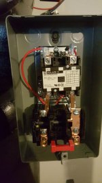
So im almost done building my air compressor. All i have left it to wire up the motor, starter, and pressure switch. The motor is a 7.5HP baldor than pulls 32 amps and the Starter is a Sqaure D.
So i believe i run wire to the starter then to the pressure switch and from there to the motor correct?
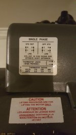
Im running a 50 amp breaker. I hear i need 8 gauge wire to be safe so ill go with that. The motor has 4 wires to wire up. (2) 10guage wires and (2) 14 gauge wires. The 14 gauge wires are Red and black. I assume the 10 gauge wires or hot wires. What are the 14 guage wires for?
Also where do i connect the wire from the break in the starter? I see four connections. Two on the bottom and two up top?
So i believe i run wire to the starter then to the pressure switch and from there to the motor correct?
Im running a 50 amp breaker. I hear i need 8 gauge wire to be safe so ill go with that. The motor has 4 wires to wire up. (2) 10guage wires and (2) 14 gauge wires. The 14 gauge wires are Red and black. I assume the 10 gauge wires or hot wires. What are the 14 guage wires for?
Also where do i connect the wire from the break in the starter? I see four connections. Two on the bottom and two up top?