To avoid these ads, REGISTER NOW!

Between 265 & 485 SQ/FT Nick's Two-Car Detached Vdub Garage

Workspaces sized between 265 and 485 squarefeet.
To avoid these ads, REGISTER NOW!

loganb

ALLIANCE MEMBER
Joined
Dec 29, 2011
Messages
5,577
Location
Omaha, NE
Oh snap... I'm borderline about to join ya in this department. Mostly a lurker on these forums, but follow many of the same people you do and damn it has been tough holding out! Go with the Ender 3v2?

My 2 cents:

Ender/Creality is the best supported, best bang for the buck if you keep it stock. Get it setup and it should print very well

Their cheaper models can print very well out of the box and they have more options for size and features than others.

Prusa is the other hobbist/consumer grade machine with a huge following and top reviews. Most of the upgrade features like direct drive, quiet boards, all metal hot end that are upgrades on Ender are standard on Prusa...so the machine costs more.

If you're someone who isn't content with "stock" anything...you'll often have as much in a Creality by the time you're done as if you spent more to begin with and went to Prusa or Voron or another more optioned machine. I bought a Prusa to start, love it but wouldn't hesitate recommending an Ender
 

Matias

Well-known member
Joined
Feb 28, 2015
Messages
616
Location
Finland
Ope! (as we say in Minnesota)


Guess I'll be getting a lump of coal for Xmas, because I've been naughty. Thanks a lot Garage Journal! :ROFLMAO:

Haha, nice! Even if you get some coal, you you'll also be able to print some additional gifts for yourself, like the flagstop, extrusion T-nut etc :)
 
OP
N

nicholam77

Well-known member
Joined
Dec 18, 2016
Messages
2,671
Location
Minneapolis, MN
Oh snap... I'm borderline about to join ya in this department. Mostly a lurker on these forums, but follow many of the same people you do and damn it has been tough holding out! Go with the Ender 3v2?

Yes, Ender 3 v2. At this phase in my life I want the path of least resistance (good documentation and support, hopefully less messing around). Look out, you'll be next!

YESSSSS!!!!!!!! 🤣🤣🤣🤣🤣

Thanks to you Bret!

That chewed up cord is probably from a squinney.


Once they get a taste for copper (or aluminum), nothing is safe. We had a serious issue with them on the farm. It got so bad that it wasn't safe to even park cars outside because they'd chew on any wiring they could access. Dad waged war on them and eventually got rid of the problem animals. I've had issues with them chewing the aluminum ties on the chain link gate, but (fingers crossed) no issues with cars yet.

How have I never heard "squinney" before? I call them 13-striped ground squirrel haha. I didn't know they like metals. haven't seen any around my property but I'd wager you're probably right. Animals eat the weirdest things. The squirrels in my yard have eating massive chunks out of out IKEA patio table, which I'm pretty sure is some sort of fiberglass.

As Queen says "Another one bites the dust!" Love it and I think you will too!

:ROFLMAO: I'm a little overwhelmed getting it setup and all the software and stuff to learn, but I'm excited! I'm hoping to be able to use it the way you have with some functional prints for the shop.

Haha, nice! Even if you get some coal, you you'll also be able to print some additional gifts for yourself, like the flagstop, extrusion T-nut etc :)

Very true if I can get a hang of the modeling! Saw you got one too, have fun!

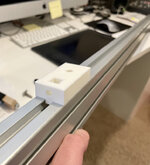
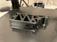
I actually did a test print of the flag stop block yesterday:

IMG-4559.jpg

IMG-4561.jpg


I haven't done any calibration other than bed leveling, so I was pretty impressed out of the box with the accuracy.

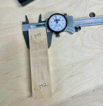
I made the holes 6mm ID in Fusion for M6 bolts, but they were a tight fit and the threads were catching as they printed 5.72mm ID for some reason. I'll have to figure that out. Obviously can build some tolerance into the model but hoping to get it a bit more accurate. But it's already a much better fit than my wood version!

No Perkele! (as we say in Finland) :ROFLMAO: Congrats! Best solution for the 3D fever. I think you will like it(y)

Thanks T, I think you're right. You helped tip me over the edge!
 
OP
N

nicholam77

Well-known member
Joined
Dec 18, 2016
Messages
2,671
Location
Minneapolis, MN
Question for you 3D printer guys, what procedure should I be looking at if I'm trying to get the X-Y-Z dimensions more accurate. I printed the 20mm test cube and all axis were a bit off. I have found tons of videos on printing that cube, but having trouble finding how to make adjustments to correct for inaccurate dimensions. Let me know if you have any hot tips!

For reference my cube came out ~ 19.9 x 19.89 x 19.7 mm. I'm not sure how good of accuracy to expect, but hoping to be more equal and maybe not more than .1mm off?
 

loganb

ALLIANCE MEMBER
Joined
Dec 29, 2011
Messages
5,577
Location
Omaha, NE
Question for you 3D printer guys, what procedure should I be looking at if I'm trying to get the X-Y-Z dimensions more accurate. I printed the 20mm test cube and all axis were a bit off. I have found tons of videos on printing that cube, but having trouble finding how to make adjustments to correct for inaccurate dimensions. Let me know if you have any hot tips!

For reference my cube came out ~ 19.9 x 19.89 x 19.7 mm. I'm not sure how good of accuracy to expect, but hoping to be more equal and maybe not more than .1mm off?

To start with....I wouldn't worry about it

Remember that 1mm is slightly over 1/32" of an inch....so .1mm to say the least impossible to measure with a tape measure :)

There is a lot of potential things that can impact dimensions including filament, speed, was it printed "solo" or as part of a larger batch, nozzle size etc

You're in the range that you'll get very close prints and if it was me that'd be close enough to keep printing and learning more. As you get your preferred filament and start playing with settings you can work on dialing it in if necessary but for a first time printer owner/user, I personally thing I got a lot more "education" out of playing and learning with different settings/items/filaments after proving it was making tape measure accurate prints and trying to dimensional offsets after I was more experienced
 
OP
N

nicholam77

Well-known member
Joined
Dec 18, 2016
Messages
2,671
Location
Minneapolis, MN
Nick,

This guy is the one I followed to calibrate mine. He has a website as well. What slicer are you using?


https://www.youtube.com/c/TeachingTech

Bret

Thanks Bret, that is very helpful and I actually came across that one today. Well I started watching this, which references that video and website. I wasn't sure if something like the e-steps correction would address X-Y-Z differences but maybe it does.

I think I am getting ahead of myself as I have not done most of the calibrations yet, had to get a dang USB C-to-A cable so I can try that pronterface whatchamacallit. 😁

I'm using Ultimaker Cura for a slicer.

To start with....I wouldn't worry about it

Remember that 1mm is slightly over 1/32" of an inch....so .1mm to say the least impossible to measure with a tape measure :)

There is a lot of potential things that can impact dimensions including filament, speed, was it printed "solo" or as part of a larger batch, nozzle size etc

You're in the range that you'll get very close prints and if it was me that'd be close enough to keep printing and learning more. As you get your preferred filament and start playing with settings you can work on dialing it in if necessary but for a first time printer owner/user, I personally thing I got a lot more "education" out of playing and learning with different settings/items/filaments after proving it was making tape measure accurate prints and trying to dimensional offsets after I was more experienced

1/32 sounds so much smaller than a millimeter, I didn't realize they were that close!

It's not so much that I care about perfect accuracy, except when auxiliary non-3D-printed parts are involved. I was just surprised that my CAD model specified a 6 mm opening, and my calipers say the diameter including threads on the M6 bolt I'm using is 5.85 mm, and it still didn't fit in the hole because it printed even smaller at 5.74 mm. Maybe not enough to discern on a tape measure but the bolt still didn't fit. Neither did the nut I made the opening for based on a McMaster CAD part.

So I guess I'm wondering... am I always supposed to make the opening in the model bigger to accommodate? If so, it seems counterintuitive to take careful measurements with calipers if that all has to be adjusted. But I am completely new to this so I don't really know what to expect as far as process goes.

But yeah, you're right, as much as I want to dive head first into modeling custom stuff I need to spend some basic time with the printer and get my bearings.
 

bj383ss

Well-known member
Joined
Sep 29, 2011
Messages
3,166
Location
TX
Nick,

This guy is really good too. He goes into to depth how to tune the cura slicer. After I changed everything to his settings thats when I was able to print a perfect 20mm cube.

Bret
 
OP
N

nicholam77

Well-known member
Joined
Dec 18, 2016
Messages
2,671
Location
Minneapolis, MN
Nick,

This guy is really good too. He goes into to depth how to tune the cura slicer. After I changed everything to his settings thats when I was able to print a perfect 20mm cube.
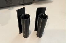
Thanks Bret, I'll check that one out!

_______________________________________________________


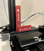
I still have to do a deep dive with calibration stuff, but I've done some minor checking and tweaks, like checking the assembly for square:

IMG-4576.jpg

It was pretty good but not perfect. Hopefully good enough.

And made sure the stepper motor carriages were gliding smooth and tensioned right.

I also upgraded the pesky bed leveling springs.

IMG-4572.jpg

I want to get it all operating in tip top shape, but I couldn't help myself and jumped into printing a few useful models!

First up is a little organizer for the drawer and tools that comes with it:

IMG-4574.jpg

Then a few things for the garage, like these pencil holders:

IMG-4575.jpg

IMG-4577.jpg

IMG-4579.jpg

I'm always looking for my pencils so I might print more and just put them everywhere haha.

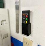
Then I printed this cool little holster for my air cleaner remote:

IMG-4567.jpg

IMG-4570.jpg

IMG-4582.jpg

Now it's easily accessible instead of in a drawer, and I can still remove it and carry it around. The fit was awesome.

Lastly I printed this replica Microjig "X-Pad" base for their dovetail clamps:

IMG-4571.jpg

It pressure fits on the existing pad and is pretty cool because it applies downward and sideways pressure simultaneously:

IMG-4585.jpg

So with some bench dogs you can hold a piece nicely against them with one clamp. I could see this being useful to push a workpiece against a fence, or push two pieces together.

IMG-4586.jpg

I was worried I would not find enough things to print, but I've already found or thought of a ton of stuff I want to do! Honestly I haven't been this excited about shop organization in awhile.

🍻
 

Bakafish

Well-known member
Joined
Feb 7, 2017
Messages
477
Location
Tokyo
Fusion360 actually will generate threaded holes (Create->Threads) that print shockingly well for me. Make sure to check the "Modeled" checkbox. It will also do dimensional counterbore and clearance holes, but try making some threaded ones first. You can run a tap through them if they are tight, but typically they work really well out of the box and are quite strong. Super useful feature to utilize.

The dimensional calibration is a bit of a rabbit hole that has a lot of other dependencies that are not exactly obvious. The external dimensions and internal feature accuracy are also slightly differently adjusted, and all of it is going to change based on the filament, temperature and extrusion settings, so delay messing with it until you really need to. With small stuff it is often easier to just reprint after making small dimensional compensations in the model.

I'm glad to see you pumping out the plastic!
 
OP
N

nicholam77

Well-known member
Joined
Dec 18, 2016
Messages
2,671
Location
Minneapolis, MN
Thanks @Bakafish . For this specific application I wanted clearance on the bolt, but that is awesome about the thread tool. I did make a slight modification to the model and reprint and it worked great. I was just unsure if that's the norm but it sounds like it is, to print and tweak and reprint.

Question for you — a bit ago you mentioned setting up "macros" on your mouse to control the orbit in Fusion360? What exactly do you mean by that? (sorry for my thick-headedness). My mouse only has one auxiliary side button, but I would really love to be able to use keyboard modifiers (like shift and space) to temporarily enter "pan" and "orbit" only while the key is held. Sketchup has this, so does Cura slicer, and many other 3D programs so you don't have to enter a tool and exit a tool every time you want to adjust the view. I can't figure this out in 360 — is this what you meant with your mouse macros, and if so would you mind walking me through how you set that up? I'm on MacOS if that matters. Feel free to send me a PM, too.

Also, after complaining about the orbit earlier I found that changing it to "Constrained Orbit" instead of "Free Orbit" it behaved much more like I am used to.

I am enjoying the 3D printer very much so far. The stuff you've made with yours has been a big inspiration to give it a try.
 
OP
N

nicholam77

Well-known member
Joined
Dec 18, 2016
Messages
2,671
Location
Minneapolis, MN
Short update on the MFT Flip Stop.

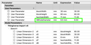
I tweaked the model for the stop block so the M6 holes are slightly oversized and that worked well. When I made the model I attempted to add some User Parameters to try out the concept of parametric modeling. This was AWESOME when it came to changing the dimension and having the model update.

For those reading along that aren't CAD wizards much like I am not, basically you can set a text string parameter as a value or formula. In this case, I saved the parameter "M6holeDiameter", and used that to set the dimension every time I wanted an M6 hole. The value started at 6mm of course. When that turned out to be too tight, I could just update the parameter value to 6.5mm, and then all the M6 holes in my model adjusted accordingly. I see the huge value in this, especially for 3D printing where adjustments probably have to be made quite a bit. In Sketchup this would be a nightmare.

fusion-parameters.png

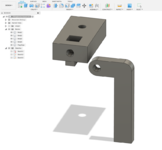
So with the block dimensions solved, I quickly modeled the flag stop:

fusion-flip-stop.png


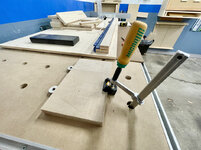
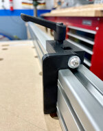
Added the lever knob from McMaster at some hardware from the hardware store, and it worked!

IMG-4593.jpg

Overall, I'm pretty pleased with it. The only thing I need to tweak is the rigidity of the flag stop. It has too much play. I've reprinted several times, and now I'm doing one (in progress) where I've upped the wall count (5x) and infill to 90% which hopefully will make it strong enough, in addition to making it a little thicker.

Here's a quick YouTube vid that shows it in more detail, as well as the current "flex":


Cheers!

🍻
 

Bakafish

Well-known member
Joined
Feb 7, 2017
Messages
477
Location
Tokyo
Question for you — a bit ago you mentioned setting up "macros" on your mouse to control the orbit in Fusion360? What exactly do you mean by that? (sorry for my thick-headedness). My mouse only has one auxiliary side button, but I would really love to be able to use keyboard modifiers (like shift and space) to temporarily enter "pan" and "orbit" only while the key is held. Sketchup has this, so does Cura slicer, and many other 3D programs so you don't have to enter a tool and exit a tool every time you want to adjust the view. I can't figure this out in 360 — is this what you meant with your mouse macros, and if so would you mind walking me through how you set that up? I'm on MacOS if that matters.
I'm on MacOS as well, but this will work on Windows too. The software to set up the buttons is part of the Logitec (called Logicool here in Japan for some stupid reason) drivers. I use their MX3 mouse which I find to be a pretty good unit, cheaper and wired mice from them should work as well if they have enough buttons. The software itself has limitations as to what modifier keys you can assign to couple with alternate button press events (middle click and right click) so you can't make it assign something like (Shift + Option + Middle click) to a button which is unfortunate. So I found using the Alias set of keyboard shortcuts for movement in the F360 preferences was the only set of commands that allowed me to assign Pan (Middle click) to [thumb button 1] and Orbit (Shift + Option + Click) to [thumb button 2] which feels very natural to me, and gets me around my work quickly. Since these mouse button macros can be set globally or per-application, you can assign them so that Cura behaves the same way, keeping the 3D movements consistent across applications.

If you love your mouse and cannot part with it, or want to use a different brand or something, there is 3rd party software like USB Overdrive (I used this since pre-OS X days) out there that can work similarly to the Logitec application for the Mac and I'm sure something similar for Windows.
 

Bakafish

Well-known member
Joined
Feb 7, 2017
Messages
477
Location
Tokyo
Here's a quick YouTube vid that shows it in more detail, as well as the current "flex":
You may want to put two protrusions on the inside face of the flag that engage the slots in the extrusion. These will help keep it from deflecting as much as it will not be able to easily rotate in that direction when they are snapped into place. You may need to slightly radius them based on the pivot point, should be easy to do in Fusion. Infill is likely not the issue, 90% is overkill, although more shells and top/bottom layers will absolutely help.
 
OP
N

nicholam77

Well-known member
Joined
Dec 18, 2016
Messages
2,671
Location
Minneapolis, MN
@Bakafish thanks for the info on the button mapping, I’m using a Razer mouse that I otherwise like, but I’ll look into that as it would speed things up I think. I haven’t downloaded their drivers yet.

Tabs on the flip stop was going to be my next move if it still flexes 😄, but it’s reassuring to hear you suggest it! Thanks for the tip on the infill vs walls and top/bottom layers. Obviously I’m still learning what effect each setting has!
 

loganb

ALLIANCE MEMBER
Joined
Dec 29, 2011
Messages
5,577
Location
Omaha, NE
If you haven't found it, check out CNC Kitchen channel on youtube, some great videos testing strength differences between material types and print settings

For parts without significant compressive strength requirements, I usually print 5% infill in gyroid pattern for PLA
 
OP
N

nicholam77

Well-known member
Joined
Dec 18, 2016
Messages
2,671
Location
Minneapolis, MN
Thanks @loganb

I saw your comment on gyroid in Bret's thread and I've been trying that. 5% seems so low but I trust you!

I'll check out the CNC Kitchen, sounds like a good primer because a lot of these settings I have no idea what's right. I've pretty much been sticking to defaults or recommended settings but it would be nice to know the pros and cons of different approaches and when to use them.


______________________________________________________________

A quick print from today, I found this "clutch stop" on Thingiverse for my car:

IMG-4588.jpg


IMG-4590.jpg

It's function is to shorten the travel of the clutch pedal. VW's are known (at least the ones I've driven) to have a fairly long pedal travel and a high engagement point. I'm used to that and kind of like it, but I've always been curious to try a clutch stop in this Mk7 because I've always thought the clutch operation is very mediocre. Driving around it's a bit different feel of course, but I think I'm liking the take-up better. Going to keep it in for awhile and see if I like it or hate it.

And I printed another Ender mod and my trickiest print so far:

side-spool.png

It's a bracket that holds the filament spool off to the side of the extruder. With the spool mounted on top of the machine I had the filament snap on me mid-print one time, and it just makes no sense to have it coming in the extruder at almost a 90° angle. I thought about doing one of the filament guides that hangs off the side, but moving the whole spool to the side seemed to make more sense to me.

For whatever reason I kept having bed adhesion and warping issues with this part. I restarted it 3 or 4 times with different slicing.

IMG-4601.jpg

I even tried a "brim", but in the end I just accepted a warped part because it didn't really affect it structurally or functionally.

It fit very tight, and I haven't tried a print yet but it seems to position the spool in an ideal way:

IMG-4603.jpg

That's it for today!
 

Bakafish

Well-known member
Joined
Feb 7, 2017
Messages
477
Location
Tokyo
That warping is strange, I use 60C bed temperature with PLA. Make sure it isn't subjected to breeze induced temperature swings during the first few layers too. Get some 99% Alcohol and dust free wipes and give the glass a quick wipe down just before printing. It is actually coated with a thin layer that gets 'activated' a bit by the alcohol. If I'm printing a really tricky object that has a low contact area I sometimes use a quick rub with a glue stick followed by a smoothing wipe with a wet tissue. Glue sticks can help when you are getting TOO much adhesion, which I experience sometimes as well.

If you are still having a lot of trouble I'd start suspecting the filament which is always one of biggest variables. Invest in a roll of top quality stuff so you at least have a reference point. The cheap CN products can be quite good, but there are batch differences and brands come and go. Dialing everything in takes time and once it is working it ***** to have to do all that over again, so once you find a good filament, stock up on it or make sure the manufacturer will be around for a while :)
 
To avoid these ads, REGISTER NOW!

loganb

ALLIANCE MEMBER
Joined
Dec 29, 2011
Messages
5,577
Location
Omaha, NE
Agree that warping like that on PLA seems odd...do you have another roll of filament you can try? I use the default temp settings of 60 and 215 and have never had issues like that.

As for filament brands, I've had good success with Hatchbox, Overture and Sunlu, all easily orderable via Amazon.

And that clutch atop looks nice! Way to quickly spread 3d printing to the VW hobby ;)
 

bj383ss

Well-known member
Joined
Sep 29, 2011
Messages
3,166
Location
TX
I have had warping like that on a few of the bins I made. Not sure either the cause. One thing I can say is take your bed off and wash it at least once a week. The PLA has oils in it that overtime get stuck on the bed. Even with the Alcohol cleaning you might still have adhesion problems. I can't remember what i was printing. I restarted it 3 times and my buddy suggested washing the plate. It worked fantastic afterwards. I also have used masking tape on a part that had very little contact patch.

One last thing you can try is slowing down the first layer print speed and see if it helps. I have not gone down to 5% infill yet. But I do consistently use 10% and the gyroid option.

I also added a dryer to mine to pull the moisture out of the filament. I have been using Overture since day one. I have only had one bad spool of Red that kept snapping.

51662618686_ab7ca857b6_b.jpg20211107_171326 by bjohnson388, on Flickr

Bret
 
OP
N

nicholam77

Well-known member
Joined
Dec 18, 2016
Messages
2,671
Location
Minneapolis, MN
That warping is strange, I use 60C bed temperature with PLA. Make sure it isn't subjected to breeze induced temperature swings during the first few layers too. Get some 99% Alcohol and dust free wipes and give the glass a quick wipe down just before printing. It is actually coated with a thin layer that gets 'activated' a bit by the alcohol. If I'm printing a really tricky object that has a low contact area I sometimes use a quick rub with a glue stick followed by a smoothing wipe with a wet tissue. Glue sticks can help when you are getting TOO much adhesion, which I experience sometimes as well.

Thanks @Bakafish . I had been using 50° C bed temp but tried 60° C that last attempt. Although I think it was set to print 60° C on the initial layers anyways.

I'm guessing maybe it needed to be cleaned like you said. I have not attempted the glue stick yet but will keep it in mind.

Agree that warping like that on PLA seems odd...do you have another roll of filament you can try? I use the default temp settings of 60 and 215 and have never had issues like that.

As for filament brands, I've had good success with Hatchbox, Overture and Sunlu, all easily orderable via Amazon.

I've only bought one roll of filament so far. It's Microcenter's in house brand which I read is just repackaged "eSUN", which I at least read good things about but who knows. No issues like that with any other prints off the same roll. Thanks for the brand recommendations, I'd like to get more colors but want to figure out storage (vacuum bags?) and don't want to break the bank until I know which colors or materials I want.

And that clutch atop looks nice! Way to quickly spread 3d printing to the VW hobby ;)

Yeah I was impressed, it fit perfectly and even refused the factory rubber bit where the pedal makes contact so it feels very OEM.

One thing I can say is take your bed off and wash it at least once a week.

Interesting, what do you wash it with? Dish soap? Are you using the carborundum side of the plate or the glass side? My initial layers are slowed to 20 mm/s, guess I could try slower but I'm thinking like everyone suggested maybe it just needed a clean. It kept happening in the exact same spot so maybe there was some residue.

Now I have to Google filament dryers. 😁
 
OP
N

nicholam77

Well-known member
Joined
Dec 18, 2016
Messages
2,671
Location
Minneapolis, MN
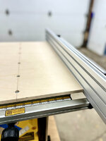
MFT Fence Improvements

To finish out the whole stop block venture, I can confirm that adding the extra 2mm of thickness and more "walls" helped with the rigidity. I might reprint with even more walls, but for now it should work just fine as long as I'm mindful of not pushing on it.

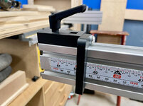
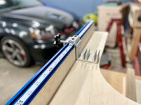
Something I've been meaning to add for awhile is a measuring scale, but was waiting on the stop block solution. With that working ok, I ordered some FastCap SAE/Metric peel and stick measuring tape, because I really like their super readable scales, and I wanted metric as well because I think the next cabinets I do I'm going to move to metric.

Kind of odd but you put down an adhesive double-siding tape first, and then the scale:

IMG-4652.jpg

IMG-4654.jpg

One benefit to the 30x60 extrusion is the 3/4" wide Fastcap scale fits perfectly on the middle surface.

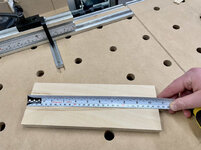
To calibrate the fence (keep in mind I "assemble" the MFT every time I use it), I take a known reference piece of plywood and place it against the fence:

IMG-4667.jpg

Then I plunge the saw so the blade goes all the way into the kerf, and **** the end of the known reference piece against it. This references exactly where the saw will cut. There is some play when attaching the rail and fence etc, so it's important to have these physical references.

IMG-4669.jpg

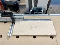
Then I set the flip stop to the same measurement as the known reference piece, in this case 250mm:

IMG-4666.jpg

Then I loosen the socket cap bolts on the back of the fence and slide it towards the saw until the flip stop just kisses the other end of the known reference piece. This should put the flip stop and thus the scale at the appropriate distance from the blade.

IMG-4670.jpg

Maybe this stuff is obvious but I'm always chasing accuracy and trying to eliminate setup errors, so hopefully it could help someone. Let's do a test cut.

I set the flip stop to 270mm on the scale and make a cut.

IMG-4658.jpg

The results:

IMG-4661.jpg

IMG-4664.jpg

Perfect!

I'm pretty pleased to have this built in measuring tape that is millimeter-accurate with the setup process.

The total crosscut capacity using the stop is 49 1/2 inches.

IMG-4673.jpg

And one wide shot of the whole setup:

IMG-4672.jpg

🍻
 
Last edited:

zanyad

ALLIANCE MEMBER
Joined
Apr 26, 2018
Messages
2,804
Location
NE Ohio
MFT Fence Improvements

<SNIP>

To calibrate the fence (keep in mind I "assemble" the MFT every time I use it), I take a known reference piece of plywood and place it against the fence:

IMG-4667.jpg

Then I plunge the saw so the blade goes all the way into the kerf, and **** the end of the known reference piece against it. This references exactly where the saw will cut. There is some play when attaching the rail and fence etc, so it's important to have these physical references.

IMG-4669.jpg

Then I set the flip stop to the same measurement as the known reference piece, in this case 250mm:

IMG-4666.jpg

Then I loosen the socket cap bolts on the back of the fence and slide it towards the saw until the flip stop just kisses the other end of the known reference piece. This should put the flip stop and thus the scale at the appropriate distance from the blade.

IMG-4670.jpg

<SNIP>

IMG-4672.jpg

🍻
Why not drill & ream pin holes for steel dowel pins once you have everything aligned? Standard in fixturing for machining is to use one round pin for location in two directions, and one diamond pin for rotational orientation around that location point. See this guide from Carr Lane for some good details.
 
OP
N

nicholam77

Well-known member
Joined
Dec 18, 2016
Messages
2,671
Location
Minneapolis, MN
Why not drill & ream pin holes for steel dowel pins once you have everything aligned? Standard in fixturing for machining is to use one round pin for location in two directions, and one diamond pin for rotational orientation around that location point. See this guide from Carr Lane for some good details.

If I'm understanding you correctly the pins would go into the MDF top? To be honest, I hadn't thought of that! But I will say... I don't find MDF to be very stable with the climate swings in Minnesota, and it's kind of a weak material. My dog hole pattern isn't perfectly square, but even if it was, there is enough expansion and contraction from winter to summer that my bench dogs fit loose and have play in the winter. Not a lot, but depending on the reference distance it could add up. I guess maybe I'd be worried the same would happen to embedded locating pins unless I found some way to correct for that.

If I'm misunderstanding the approach feel free to correct me, I have no machinist background whatsoever 😁

Even your Jenga pile of off-cuts is tidy.
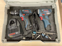
Ha! Unfortunately I hoard every little piece like and they tend to creep to other surfaces. I really need more dedicated storage for them.
 
OP
N

nicholam77

Well-known member
Joined
Dec 18, 2016
Messages
2,671
Location
Minneapolis, MN
12v Systainer Bit Storage

Here's a quick one from the 3D printer.

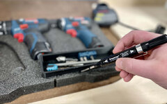
There's a handful of bits I keep with my 12v Bosch drills that I use with them most often. So I don't have to go searching in a drawer somewhere for where I put them last.

I had Kaizen-foamed the Systainer a long time ago, but one thing that's always irritated me is the bits roll around in an untidy blob.

IMG-4703.jpg

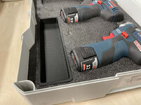
So I modeled this box for them in Fusion360. Overall still struggling with Fusion, but simple stuff like this I can handle.

tloc_drill_box.png

I only made the walls and lip 1mm, which I think was too thin, but it took a long time to print so I'm using it anyway.

IMG-4701.jpg

If you've ever used Kaizen foam, you'll know it's a royal pain in the ***. :ROFLMAO:

IMG-4704.jpg

IMG-4706.jpg


Is it a monumental difference in functionality? Not really. But it satisfies my OCD and looks nice.
 

zanyad

ALLIANCE MEMBER
Joined
Apr 26, 2018
Messages
2,804
Location
NE Ohio
If I'm understanding you correctly the pins would go into the MDF top? To be honest, I hadn't thought of that! But I will say... I don't find MDF to be very stable with the climate swings in Minnesota, and it's kind of a weak material. My dog hole pattern isn't perfectly square, but even if it was, there is enough expansion and contraction from winter to summer that my bench dogs fit loose and have play in the winter. Not a lot, but depending on the reference distance it could add up. I guess maybe I'd be worried the same would happen to embedded locating pins unless I found some way to correct for that.

If I'm misunderstanding the approach feel free to correct me, I have no machinist background whatsoever 😁
Yes, the pins would go into your fence and the table, just like doweling a piece of furniture together. I thought MDF is more dimensionally stable than that. In machining fixturing you also have to take different thermal expansion coefficients into consideration, but only if working in dissimilar metals. Even aluminum to steel is usually okay.

Another approach that works in machining is using undersized dowels in a mill's T-slot. The holes in the fixture are undersized so the dowels are press fit, and then you press the dowels up against the edge of the T-slot while tightening the fixture to the table. Can you use the T-slots on the edge of your MFT as a reference edge to align against? Either the T-slot itself, or the outside edge of the extrusion. I am, however, not familiar with the design of MFT's (other than to recognize one when I see it) or of your track square, so I may be approaching this in an incorrect manner. HTH!
 
OP
N

nicholam77

Well-known member
Joined
Dec 18, 2016
Messages
2,671
Location
Minneapolis, MN
Yes, the pins would go into your fence and the table, just like doweling a piece of furniture together. I thought MDF is more dimensionally stable than that.
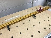
Ah, gotcha, that's what I figured. I thought MDF was more dimensionally stable, too, and maybe it's good enough. But I have noticed variance in how tight or loose my bench dogs fit based on the time of the year. And all of the MDF door and window casings I didn't glue the miters on in my house very obviously open up every winter.

That said, a common approach to setting up these MFT tables is basically what you're saying, but using tight fitting 20mm bench dogs as the "pins", and the hole grid as the reference holes.

Example:

IMG-3944.jpg

That doesn't work for me because my hole grid isn't perfectly orthogonal, but in theory it should work for a CNC'd product like the official Festool MFT.

I suppose I could add some special locating pins for that purpose, but I don't know if I trust myself to drill them accurately enough and to be honest my current setup process only takes a few minutes so it's not something I feel like I need to chase. Maybe on the next bench 😁

Can you use the T-slots on the edge of your MFT as a reference edge to align against? Either the T-slot itself, or the outside edge of the extrusion. I am, however, not familiar with the design of MFT's (other than to recognize one when I see it) or of your track square, so I may be approaching this in an incorrect manner.

That's interesting, I wouldn't have thought of that. I'd probably need to rework my current setup too much because I'd need a way to fasten the fence down, and the T-Track is on the very edge. But yes I think it could be done.

Good stuff Nick! You are on fire with the 3D printer (y) Love the drill systainer!

Thanks T, I am enjoying the printer quite a bit. I still need to do a deep dive on the slicing software and dial some stuff in for better prints, but I've been too busy printing stuff to do that. :ROFLMAO:

I actually have another thing cooking on it right now.
 
OP
N

nicholam77

Well-known member
Joined
Dec 18, 2016
Messages
2,671
Location
Minneapolis, MN
We got our first snow of the year (2" but didn't stick to much) this weekend.

IMG-4755.jpg

I'm always amazed how it goes from Fall to Winter in 24 hrs. Definitely feels like hibernation mode now.

Too bad my 3 enormous silver maples still have half their leaves :rolleyes:

We completely raked the yard on Saturday, and today it appeared to be pointless:

IMG-4756.jpg

The colder weather did prompt me to do the first fire of the season. And I did make good on my idea to use some cherry hand plane shavings as tinder 😁

IMG_2967.jpg

IMG-4744.jpg

IMG-4749.jpg

Last Thursday I did start another smallish shop project, but you'll just have to wait and see until I'm farther along!

IMG-4689.jpg

Hope everyone had a great weekend!
 
Last edited:

bdbecker

ALLIANCE MEMBER
Joined
Nov 18, 2015
Messages
5,574
Location
Iowa
Not sure how much room you've got left between the tray and the case, but you could glue a couple of magnets on the bottom of the tray to further aid in bits not rolling around inside the box.

I've got the same problem with leaves. Probably out of laziness more than anything else, but I usually wait until as late in the fall as I dare to start any sort of leaf cleanup for the exact reason you posted. I figure its probably the same amount of time overall to just hit it in one shot rather than trying to keep up with it throughout the fall. We've got some warmer weather on deck for this week, so I'll probably try to work through it over the next few days.

That fire looks cozy!
 

Mr. Roboto

Well-known member
Joined
Dec 11, 2012
Messages
2,160
Location
New Hampshire
Nick, just popped in to get caught up. Nice pickup on the 3D printer. The possibilities are endless with that! Looks like you’ve already put it to good use, and I can’t wait to see what else you come up with. Nice skill to pick up, too.

No snow here yet. It’s actually been unseasonably warm lately. The leaves are also an endless battle here as well. Been tough to get anything done lately with the newborn, and I just went back to work this week too. So, I’m in “keep my head above water” mode now haha.
 
OP
N

nicholam77

Well-known member
Joined
Dec 18, 2016
Messages
2,671
Location
Minneapolis, MN
Not sure how much room you've got left between the tray and the case, but you could glue a couple of magnets on the bottom of the tray to further aid in bits not rolling around inside the box.

There is some room, interesting idea!

Nick, just popped in to get caught up. Nice pickup on the 3D printer. The possibilities are endless with that! Looks like you’ve already put it to good use, and I can’t wait to see what else you come up with. Nice skill to pick up, too.

Thanks, ya I'm enjoying the 3D printer so far! I really did not think I would have a lot of use for it, at least enough to offset the cost of the machine for some reason, despite seeing the cool things others on this board were doing. But now I have a laundry list of things I want to print and/or design.

No snow here yet. It’s actually been unseasonably warm lately. The leaves are also an endless battle here as well. Been tough to get anything done lately with the newborn, and I just went back to work this week too. So, I’m in “keep my head above water” mode now haha.

I feel ya. I still feel like I'm in "keep my head above water" mode haha, but the early days are especially difficult. For us 4 months has gone by really fast and while not easy, it's significantly better already. I wanted more time but was only able to take 2 or 3 weeks off work this time around. You got a lot done before the baby, so hang in there and just enjoy that jeep and office space and the newborn!
 
OP
N

nicholam77

Well-known member
Joined
Dec 18, 2016
Messages
2,671
Location
Minneapolis, MN
Another quick 3D print:

Desk top phone stand so I can keep an eye on Garage Journal while I work :ROFLMAO:

IMG-4760.jpg

This print turned out pretty nice, although kind of rough where the supports broke away.

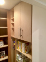
In other news, I suggested to my dad we make some prototype doors for his pantry. I haven't done any work on that project until now because of the baby, but I don't want to neglect it all winter or it will go unfinished for half a year. Unfortunately my only real time to work on it is after 8pm and it's getting cold, fast.

I didn't take any pics, but we sliced up some MDF to the expected door size for one of the cabinets as a test. I used the the table saw for the rips and the MFT w/fence scale and flip stop for the crosscuts and it came out perfect, with two identical, square parts.

I'm new to cabinet doors but it's a bit of a math headache. My dad has drawings, but of course there are slight variances in plywood thickness and the actual cabinet that got built vs. the schematics.

The boxes are 3/4" ply (actually 15/16"), and he wants a 1/16" reveal on the edges and a 1/8" gap where the pair of doors come together.

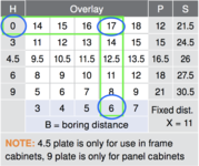
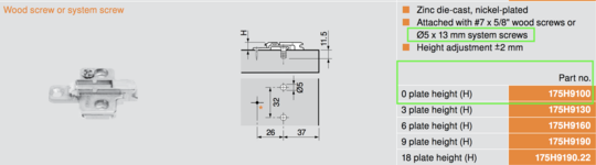
Here are some Blum charts that helped us figure it out:

Blum-2.png

Blum-1.png

That second one shows the "boring distance" for the hinge cup, which is the distance in millimeters from the edge of the door, based on the hinge plate part # and the overlay you want. We had originally planned for a 6mm boring distance to give a 17mm overlay. 17mm is equivalent to 11/16", which would leave a 1/16" reveal on 3/4" material. But because the plywood is actually a 1/16" undersized, we ending up going with the 5mm boring distance, as that gives a 16mm or 5/8" overlay, leaving the correct 1/16" reveal. Confused? I was too.

To size the doors, we took the total cabinet outside width, divided by two (2x doors), and subtracted 1/8" to account for the 1/16" reveal on each side. 1/16" + 1/16" adds up to 1/8" in the middle.

The hinge cups were drilled on the drill press with a 35mm Forstner bit. To find the distance in from the edge to drill, we added the 5mm boring distance to the radius of the 35mm bit, which totals 22.5 mm.

I did some test pieces and set the drill press fence, making an extra for a setup template when we go back to do the real doors.

Again, no pics, but my dad fitted the doors and said the overlay worked out correctly, but he mistakenly was off by an inch for the cabinet width so they wouldn't close and he couldn't test the gap between the doors. Will have to rip them down. Good to be making mistakes now instead of on the cherry. :oops:

EDIT: Here's a pic

IMG-4605.jpg

We had more flurries this morning, and it's getting cold.

IMG-4787.jpg

I really need to swap to my winter rubber and get my car cleaned up, but I've had a persistent back injury for 4 months now and I'm not sure I'm able. I'm really not prepared for winter and panic mode is setting in.

🍻
 
Last edited:
OP
N

nicholam77

Well-known member
Joined
Dec 18, 2016
Messages
2,671
Location
Minneapolis, MN
With a high of 40° F yesterday and another cold snap coming through, I felt like it was my last chance to get my winter tires on.

IMG-4839.jpg

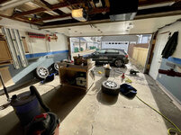
I don't normally show this angle, but here's my view of "Garage Alley" and my shared driveway.

IMG-4840.jpg

IMG-4842.jpg

The funny (sad?) thing is I don't think my wheels were this clean all season.

In the end it trashed my back again, but I figured if I took it to a shop I'd still have to carry them out of the shed, load them in the car, wash and put the summer ones away, etc. It had to be done.

A nice sunrise from this morning:

IMG-4843.jpg


🍻
 
OP
N

nicholam77

Well-known member
Joined
Dec 18, 2016
Messages
2,671
Location
Minneapolis, MN
New Table Saw Sled

So... many posts ago I made this crosscut sled fence with repurposed Kreg Top-Track from my old miter saw station.

IMG_2115.jpg

I've been storing it ever since, waiting to build a sled for it. That time has come.

I bought a piece of 1/2" baltic birch at Rockler awhile ago and forgot what I was going to do with it, so it's going to be the base of the sled.

I squared and dimensioned it with the track saw and this rail square:

IMG-4691.jpg


The MFT is very precise but sometimes it's too much effort to set up just for a few cuts. This Woodpecker rail square was a Craigslist find and does not automatically square to the rail, so you need another reference square to set it up. Fortunately I have my phenolic MFT setup square to do that. Overall it's not my preferred method to break down large sheets of plywood, but for this project it was quick and easy.

First time using the oscillating spindle sander (another Craigslist pickup):

IMG-4693.jpg

It only came with one spindle size, so I need to get some spare parts.

Made the rear fence out of 3/4" baltic birch and rounded it over on the router table.

IMG-4694.jpg

For runner bars on my past sleds I've used oak. They've held up well, but do expand and contract a bit based on the season. The miter channels in my DeWalt table saw are $#%!, and not consistent width, so I really want to minimize sloppiness.

Enter the 3D printer.

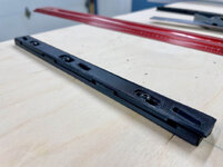
I found these Microjig Zero-Play Miter Bar clones on Thingiverse:

zero-play-guide-bars.png


IMG-4723.jpg

Each one has a top and a bottom, and they're only about 8.5" long, so I printed 4 pairs:

IMG-4802.jpg

They require some specific nuts and screws that are detailed in the Thingiverse link, and which I ordered from McMaster. About $20 including shipping.

First, some low profile hex nuts needed to be press-fit into the bottom pieces:

IMG-4810.jpg

This went ok. The fit was tight, and I had to print with supports and they weren't the cleanest recesses. I ended up using a channel lock pliers and some blocks of plywood to protect the parts and press them in.

Then assemble in top and bottom pairs like this:

IMG-4813.jpg

If you're not familiar with the Microjig product, the top and bottom slide against each other in a parallelogram action that lets the overall width match your miter slot exactly, and then you screw them tightly together.

This proved easier said than done.

Once happy with the miter fit, I drilled out counter bored holes from the top of the sled because these are designed to mount from the top:

IMG-4814.jpg

I used my MFT tenon peg support and vertical clamping to hold the sled to make them easier to attach.

IMG-4828.jpg

I spaced them like this:

IMG-4831.jpg

Put the sled in place on the saw, square it to the fence, and tighten them up through the top.

IMG-4834.jpg

Next I added the rear fence, which again the MFT was useful in making it comfortable to drill and drive the screws.

IMG-4890.jpg

IMG-4891.jpg

The front fence is two lengths of 3/4" plywood laminated, and despite running it through the table saw the bottom was not perfectly flat and it rocked a bit. I busted out the No. 4 and it definitely helped!

IMG-4894.jpg

IMG-4895.jpg

Final step was to cut the kerf, screw on the front fence, and square it to the blade. After I ran a quick 5-cut method test.

IMG-4903.jpg

IMG-4898.jpg

So it's off by 3 thou over 5". Might be worse for larger panels but holding a square up to the light it looks good.

I didn't bother recalibrating yet for reasons I'll detail at the end, but here are some finished pics:

IMG-4899.jpg

IMG-4902.jpg

IMG-4909.jpg


It's not as nice as the one @bj383ss made, but it's really nice to have a stop block and I like the look of the plywood.

So here are my initial impressions:

Time will tell how the 3D printed runners hold up. As of now, there is some wobble when the sled is not all the way in the tracks. It's pretty solid where the rear fence passes through the blade, but some slight wiggle if the sled overhangs the back or front of the saw too much. I'm kind of disappointed in this, because I really wanted it to be as close to perfect as possible. But I'm not sure if I should fault the runners or the table saw miter channels themselves.

Making it out of baltic birch, it's way too heavy.

Other than that I like it. I don't know if I'm going to get rid of my other sleds just yet, though. I need to see if any accuracy issues with the runners pop up.

That's it for now, if you're in the U.S. have a fantastic Thanksgiving, otherwise a great weekend!

🍻
 

bdbecker

ALLIANCE MEMBER
Joined
Nov 18, 2015
Messages
5,574
Location
Iowa
...Time will tell how the 3D printed runners hold up. As of now, there is some wobble when the sled is not all the way in the tracks. It's pretty solid where the rear fence passes through the blade, but some slight wiggle if the sled overhangs the back or front of the saw too much. I'm kind of disappointed in this, because I really wanted it to be as close to perfect as possible. But I'm not sure if I should fault the runners or the table saw miter channels themselves...

Have you held a straight edge up to the slides themselves to make sure they are flat where they engage the sides of the slots? That is the same issue I have with my sled using the Incra Miter Sliders. It makes sense to me why my slides would have that issue because the way the Incra slides reduce play is by using a screw and wedge to push on the sides of the slide rail. However, I wouldn't think you'd have that issue given the way those zero-play style slides work. I wonder if there is some sort of material deflection causing "high" spots on the slide that would make it fit tight in certain spots, but loose when all the high spots are not engaged with the slots.

Link to my slides for reference. I would not recommend these if anyone is wondering.
 

Trapps

ALLIANCE MEMBER
Joined
Feb 10, 2017
Messages
2,003
Location
The Detroit Zoo
The sled looks great Nick!

I actually LOL'ed when I read and then saw the pic of the rail square. Nice find; One Time Tool from 2016...

I'm (we're?) going to need more reports on the rail square functionality. I've been looking at them for a while now thanks to Peter Millard.

Have a great Turkey Day
 
To avoid these ads, REGISTER NOW!
Top Bottom