Nicely done on the sled! Was probably one of my biggest "wtf didn't I build this before" moments after building my first one for the tablesaw and realizing how nice, accurate, repeatable and safe you can be with one!

You are using an out of date browser. It may not display this or other websites correctly.
You should upgrade or use an alternative browser.
You should upgrade or use an alternative browser.
Between 265 & 485 SQ/FT Nick's Two-Car Detached Vdub Garage
- Thread starter nicholam77
- Start date
Workspaces sized between 265 and 485 squarefeet.
OP
nicholam77
Well-known member
Have you held a straight edge up to the slides themselves to make sure they are flat where they engage the sides of the slots?
I have not held a straight edge to the 3D printed parts, but I'm guessing they're "flat enough". The problem is mostly my table saw I think. The miter slots are definitely wider at the front and back of the saw than they are in the middle by the blade. Crappy job site saw tolerances. I am wondering though if doing the two shorter runners spaced out a bit is making it worse than just one continuous runner. But I couldn't have 3D-printed that.
If it turns out to be a problem I'll just make a new base for the sled and go back to hardwood runners...
Interesting you didn't like the Incra ones. I was considering those, so good to know. Also some cam-style aluminum ones on Amazon. In the end I didn't want to spend $40+ on runners alone, as this sled was supposed to be repurposing materials on hand, but we'll see how the copycat Micro Jig ones hold up over time.
The sled looks great Nick!
I actually LOL'ed when I read and then saw the pic of the rail square. Nice find; One Time Tool from 2016...
I'm (we're?) going to need more reports on the rail square functionality. I've been looking at them for a while now thanks to Peter Millard.
Thanks!
Yeah, I haven't used the rail square much due to the MFT, which is why I searched for a cheaper one. The Woodpecker OTT I picked up was under $60 used, has a slice out of the bottom side because the previous owner cut into it somehow, and has some downsides like no auto-squaring. My thoughts on rail squares in general are — they are good if you don't have an MFT, or if you need to make a couple quick cuts where repeatability isn't important. Outside of that, an MFT with crosscut fence is better.
There are solves for this, like the TSO square with attachable parallel guide. I see Bench Dogs has a fence and stop available for their Bosch square as well. Or you can just line up to pencil marks if you're feeling confident.

For me, the MFT can handle very accurate cross cuts for almost any sized cabinet part. But one thing it can't do is square up a full 4'x8' sheet of plywood. So that's what I use the rail square for the most. The long 8' edge gets an initial rip with the track saw to cut off the factory edge. This isn't super critical how it's aligned, I usually just take off 1/4" or so. Then I use the rail square to make a perpendicular 90° cut on one of the 4' ends. After that I do all the rip cuts with parallel guides, and all the cross cuts with the MFT. But you could do those with a rail square + attachable fence.
Nicely done on the sled! Was probably one of my biggest "wtf didn't I build this before" moments after building my first one for the tablesaw and realizing how nice, accurate, repeatable and safe you can be with one!
Thanks! I've used my other sleds on pretty much every project. With the MFT I have less of a need for a large one to square panels, but the main reason for doing a new one was to make it look purdy and to add the Kreg stop I had wasting away.
OP
nicholam77
Well-known member
3D Printed Sander "Holster"
Continuing on with the 3D print adventures.
I found this holder for an ETS EC 125 Festool sander on Thingiverse. My lower-end ETS 125 REQ also has a 5" pad, so I figured it would work.
It's supposed to mount with screws like this:

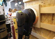
The reason I want this? With the dust hose attached, my sander has a tendency to tip over. And with large sheets of plywood, it would be nice to have a secure place to "dock" it, below the work surface, while switching work pieces. Less likelihood of tripping on it or it falling off the bench.
I printed the model as-is and it fit my sander, so all good there.
But I didn't want to screw it into the side my MFT. (I have an aversion to putting holes in things in case I want to change it later).
So I attempted to modify it in Fusion360. My first try was to import the .STL (mesh) file and convert it to a solid model. This is possible in Fusion, but with the free version it doesn't clean up all the "facets" for you. Some modifications might be easy, some might not be. But I did get it to convert, and was able to clean it up enough that I could delete the screw holes.

Of course as I was researching, I stumbled upon something else, "STEP" files. Which are solid models and have unit data. Most Thingiverse uploads seem to only have an .STL file, with the intention of sending it directly to the printer, but this one happened to include a STEP file. I opened it in Fusion360 and it came in perfect as a solid model.
I was then able to add this T-shaped bar (highlighted in blue) that should slide into the T-Track on my MFT. That way I can place the holder wherever I want, remove it, and it isn't permanent.

It's a 4 hr print, so first I printed a small section of the "T-bar" to see if the fit was good in my T-Track. A super cool thing compared to Sketchup with Fusion, is the separate "Sketches" and "Bodies". I didn't need to print the whole T-Bar length, I could just hide the model and go back to the same Sketch and extrude another shorter piece. Awesome time saver.
Anyways, that printed out well, or so I thought at this point. Test fit:

So then I printed out the full thing.

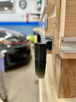

And it does hold the sander.


However, due to the weight of the sander, and the somewhat loose tolerances on the "T-bar", it pulls away from the bench and feels a little sketchy.
I think I am going to increase the T-bar thickness by about 1mm in all directions and try to get a really snug fit.
A couple of thoughts from this project:
1) 3D printing sounds like press a button and let the machine do all the work. But with the CAD time, printing test parts, and adjusting, and just with how long it takes to print stuff, it's actually pretty time consuming for "custom" work. Granted this would be a difficult thing for me to build out of wood, but still.
2) Because of the adjustments and prototyping, you end up with a lot of wasted "practice" parts. Which feels genuinely wasteful. Both in time spent, and generating additional plastic for the landfill with no real use.
3) I get that slicing software expects an .STL file, but why don't more people upload solid model files in addition? Either universal files like the STEP format or software specific like Fusion etc? It would make it sooooo much easier to tweak other's designs, and for someone who is a complete CAD novice that is super important.
Have a great weekend everybody!

Continuing on with the 3D print adventures.
I found this holder for an ETS EC 125 Festool sander on Thingiverse. My lower-end ETS 125 REQ also has a 5" pad, so I figured it would work.
It's supposed to mount with screws like this:
The reason I want this? With the dust hose attached, my sander has a tendency to tip over. And with large sheets of plywood, it would be nice to have a secure place to "dock" it, below the work surface, while switching work pieces. Less likelihood of tripping on it or it falling off the bench.
I printed the model as-is and it fit my sander, so all good there.
But I didn't want to screw it into the side my MFT. (I have an aversion to putting holes in things in case I want to change it later).
So I attempted to modify it in Fusion360. My first try was to import the .STL (mesh) file and convert it to a solid model. This is possible in Fusion, but with the free version it doesn't clean up all the "facets" for you. Some modifications might be easy, some might not be. But I did get it to convert, and was able to clean it up enough that I could delete the screw holes.
Of course as I was researching, I stumbled upon something else, "STEP" files. Which are solid models and have unit data. Most Thingiverse uploads seem to only have an .STL file, with the intention of sending it directly to the printer, but this one happened to include a STEP file. I opened it in Fusion360 and it came in perfect as a solid model.
I was then able to add this T-shaped bar (highlighted in blue) that should slide into the T-Track on my MFT. That way I can place the holder wherever I want, remove it, and it isn't permanent.
It's a 4 hr print, so first I printed a small section of the "T-bar" to see if the fit was good in my T-Track. A super cool thing compared to Sketchup with Fusion, is the separate "Sketches" and "Bodies". I didn't need to print the whole T-Bar length, I could just hide the model and go back to the same Sketch and extrude another shorter piece. Awesome time saver.
Anyways, that printed out well, or so I thought at this point. Test fit:
So then I printed out the full thing.
And it does hold the sander.
However, due to the weight of the sander, and the somewhat loose tolerances on the "T-bar", it pulls away from the bench and feels a little sketchy.
I think I am going to increase the T-bar thickness by about 1mm in all directions and try to get a really snug fit.
A couple of thoughts from this project:
1) 3D printing sounds like press a button and let the machine do all the work. But with the CAD time, printing test parts, and adjusting, and just with how long it takes to print stuff, it's actually pretty time consuming for "custom" work. Granted this would be a difficult thing for me to build out of wood, but still.
2) Because of the adjustments and prototyping, you end up with a lot of wasted "practice" parts. Which feels genuinely wasteful. Both in time spent, and generating additional plastic for the landfill with no real use.
3) I get that slicing software expects an .STL file, but why don't more people upload solid model files in addition? Either universal files like the STEP format or software specific like Fusion etc? It would make it sooooo much easier to tweak other's designs, and for someone who is a complete CAD novice that is super important.
Have a great weekend everybody!
Attachments

Last edited:
kaymccampbell
Well-known member
Check your CAD software. FreeCAD will do pretty good conversions from STL back into solids that you can modify/amend.3D Printed Sander "Holster"
Continuing on with the 3D print adventures.
I found this holder for an ETS EC 125 Festool sander on Thingiverse. My lower-end ETS 125 REQ also has a 5" pad, so I figured it would work.
It's supposed to mount with screws like this:
The reason I want this? With the dust hose attached, my sander has a tendency to tip over. And with large sheets of plywood, it would be nice to have a secure place to "dock" it, below the work surface, while switching work pieces. Less likelihood of tripping on it or it falling off the bench.
I printed the model as-is and it fit my sander, so all good there.
But I didn't want to screw it into the side my MFT. (I have an aversion to putting holes in things in case I want to change it later).
So I attempted to modify it in Fusion360. My first try was to import the .STL (mesh) file and convert it to a solid model. This is possible in Fusion, but with the free version it doesn't clean up all the "facets" for you. Some modifications might be easy, some might not be. But I did get it to convert, and was able to clean it up enough that I could delete the screw holes.
Of course as I was researching, I stumbled upon something else, "STEP" files. Which are solid models and have unit data. Most Thingiverse uploads seem to only have an .STL file, with the intention of sending it directly to the printer, but this one happened to include a STEP file. I opened it in Fusion360 and it came in perfect as a solid model.
I was then able to add this T-shaped bar (highlighted in blue) that should slide into the T-Track on my MFT. That way I can place the holder wherever I want, remove it, and it isn't permanent.
It's a 4 hr print, so first I printed a small section of the "T-bar" to see if the fit was good in my T-Track. A super cool thing compared to Sketchup with Fusion, is the separate "Sketches" and "Bodies". I didn't need to print the whole T-Bar length, I could just hide the model and go back to the same Sketch and extrude another shorter piece. Awesome time saver.
Anyways, that printed out well, or so I thought at this point. Test fit:
So then I printed out the full thing.
And it does hold the sander.
However, due to the weight of the sander, and the somewhat loose tolerances on the "T-bar", it pulls away from the bench and feels a little sketchy.
I think I am going to increase the T-bar thickness by about 1mm in all directions and try to get a really snug fit.
A couple of thoughts from this project:
1) 3D printing sounds like press a button and let the machine do all the work. But with the CAD time, printing test parts, and adjusting, and just with how long it takes to print stuff, it's actually pretty time consuming for "custom" work. Granted this would be a difficult thing for me to build out of wood, but still.
2) Because of the adjustments and prototyping, you end up with a lot of wasted "practice" parts. Which feels genuinely wasteful. Both in time spent, and generating additional plastic for the landfill with no real use.
3) I get that slicing software expects an .STL file, but why don't more people upload solid model files in addition? Either universal files like the STEP format or software specific like Fusion etc? It would make it sooooo much easier to tweak other's designs, and for someone who is a complete CAD novice that is super important.
Have a great weekend everybody!
Klokwerk
Well-known member
OH back in the day when I did support for Autodesk I'd have all the new toys....been years now and they've gone full subscription service now. So, I've been using freecad and sketchup but for 3d modeling for printing, have you tried using Blender?
OP
nicholam77
Well-known member
That's next level!
Ha, thanks Bret. I'm sure it's not impressing all the CAD wizards on here, but it's a win for me! Baby steps...
Check your CAD software. FreeCAD will do pretty good conversions from STL back into solids that you can modify/amend.
Thanks Kay. Fusion does have a convert-to-STL function which I tried, but in the free personal use version it is limited. In the paid version it does have an option called "Prismatic" which does some computing to remove unnecessary facets and clean up the model. But I don't have access to that.

Even if I did, I still think it would be far easier and better if the 3D printing community would share STEP files or similar more often.
I haven't downloaded, but have taken a peek at the FreeCAD website. I'm tempted by it since it's open source, but do you think there's enough good documentation out there for a total CAD beginner, if I were to "switch teams"? I'm not hell-bent on Fusion360 or anything, it just seemed to be the most talked about in conjunction with 3D printing, and there are a lot of resources on YouTube etc. I'm really looking for the easiest to learn solution that works and has longevity.
OH back in the day when I did support for Autodesk I'd have all the new toys....been years now and they've gone full subscription service now. So, I've been using freecad and sketchup but for 3d modeling for printing, have you tried using Blender?
I'm using the free personal-for-use license. There are a few limitations, the main being you can only have 10 editable designs at a time (which might impact complex assemblies and such but I don't think it will be an issue for my usage). It still stores everything in the cloud. And Autodesk seems to update often, so you are kind of at their whim on what they decide to add or take away. That's my biggest fear, putting a lot of time into learning a complex software and then to have the rug ripped out from under me if they decide to do something like make STL export a paid feature.
What products did you do Autodesk support for? I've never used their stuff myself as I'm a video editor, but I'm fairly familiar with their offerings as my dad was an architect (now retired), and my work (video post-production) uses their Flame and Flare finishing software, as well as Maya etc.
kaymccampbell
Well-known member
There's lots of FreeCAD FAQ and video. Never having done CAD before, I picked up the rudiments in short order. My first project was a multipart Chrysler shift knob, printed as a fully assembled unit. The second was a bunch of unobtainium dust collection fittings. Some of those were a bit more of a *****. A bit later I printed the drum clock. I liked the ability to clone objects and distribute them across the surface of my part.
None of the software products have long term viability. They're constantly changing them. Every one of them gets a bright idea to update/butcher the UI every couple years. Then you're on your own again.
None of the software products have long term viability. They're constantly changing them. Every one of them gets a bright idea to update/butcher the UI every couple years. Then you're on your own again.
OP
nicholam77
Well-known member
The second was a bunch of unobtainium dust collection fittings.
Dust collection fittings tend to be like that, don't they?

None of the software products have long term viability. They're constantly changing them. Every one of them gets a bright idea to update/butcher the UI every couple years. Then you're on your own again.
Not what I like to hear, but I do use professional software for work (not related to CAD), so I understand. If I get too frustrated with Fusion, I'll give FreeCAD a go.
OP
nicholam77
Well-known member
Paper Towel Holders / 3D Printing Troubles
All I want to do is print some paper towel holders. Is that too much to ask?
Found a model, sliced it, and BAM!

Dunno what happened there. Probably bed adhesion issue resulting in a spaghetti monster.
Next print went fine, but the model was too small for a full roll of paper towels. So I scaled it up in Cura. But then I decided I wanted to add some press-to-fit magnets to the base, so I also cracked open Fusion360 and spent some time to modify the STL file.

Printed again. And it worked!

The plan was to stick them under my Gladiator cabinets, like this:
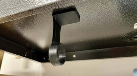
Unfortunately with the thin coated sheet metal, the grip was very, very weak.
So... I went back to the original model and printed a set of 4, this time without the magnet holes, with the intention of using double-sided tape.

Maybe I didn't have the right type of tape, but I couldn't get them to adhere to the cabinet well! I'm thinking it's the cabinet coating, and that they are textured. Maybe I needed a thicker tape. But I figured why buy something else when I can just print some with screw holes and mount to the wall instead.
So I picked a different model on Thingiverse that had some mounting screw holes, and printed that out. It looked horrible.

MAJOR layer shifting.
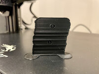
I kept tweaking and printing models trying to figure it out, but everything came out bad. And I was noticing a "thunk" sound from time-to-time.
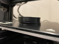
Except for this random print in the middle that came out good!
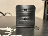
Grrrrrrr. Pulling my hair out at this point. I've probably printed 15-20 models just trying to get a pre-existing paper towel holder to work.
Do a deep dive on the interwebz. Find many people have this layer shift issue with Ender 3 V2's. Some say it's static electricity making the jump to the stepper motor wires because Creality didn't bother to ground anything. Some say it's the stepper motor drivers overheating due to inadequate cooling of the main board and possibly a faulty design. Some said loose belts skipping teeth, or too-tight belts stressing the stepper motors, or the wrong vref voltage to the stepper motor drivers, or out-of-level X-gantry, or bed plate not tight enough, or nozzle not retracting enough and hitting the part... etc etc you get the idea. Could be a million things.
What's particularly odd to me is that it only seems to happen on longer prints, and larger prints. Small and fast stuff works fine. And randomly I had one success, so it's not something like belt tension. My guess is either overheating, or possibly static electricity (I was shocked when I touched the frame recently).
This morning I popped the top cover plate to the main board and propped it up (this is literally a suggested "fix") and printed an oversized X-Y-Z cube. Only one layer shift (was accompanied by a "thunk"). Better...


That picture makes the whole print look bad but it looks better in real life.
This afternoon I went back to one of my earlier prints (the MFT stop block), and that was about 2 hrs and came out with no issues. So what gives?
At this point I'm not sure if I should:
— keep the mainboard cover cracked open
— print a modified mainboard cover and use a larger 80mm 24v fan
— upgrade the mainboard to 4.2.7 (mine is 4.2.2 and supposedly that one has more issues?). About $50 and I'm not 100% clear on the differences
— attempt to ground the stepper motors
— attempt to check or alter the stepper motor driver vref voltage
All of the above sounds like a lot of work. So yeah. Currently my paper towels and shop towel roll will have to continue to live on the bench top. And the printer is not working as it should.
All I want to do is print some paper towel holders. Is that too much to ask?
Found a model, sliced it, and BAM!
Dunno what happened there. Probably bed adhesion issue resulting in a spaghetti monster.
Next print went fine, but the model was too small for a full roll of paper towels. So I scaled it up in Cura. But then I decided I wanted to add some press-to-fit magnets to the base, so I also cracked open Fusion360 and spent some time to modify the STL file.
Printed again. And it worked!
The plan was to stick them under my Gladiator cabinets, like this:
Unfortunately with the thin coated sheet metal, the grip was very, very weak.
So... I went back to the original model and printed a set of 4, this time without the magnet holes, with the intention of using double-sided tape.
Maybe I didn't have the right type of tape, but I couldn't get them to adhere to the cabinet well! I'm thinking it's the cabinet coating, and that they are textured. Maybe I needed a thicker tape. But I figured why buy something else when I can just print some with screw holes and mount to the wall instead.
So I picked a different model on Thingiverse that had some mounting screw holes, and printed that out. It looked horrible.
MAJOR layer shifting.
I kept tweaking and printing models trying to figure it out, but everything came out bad. And I was noticing a "thunk" sound from time-to-time.
Except for this random print in the middle that came out good!
Grrrrrrr. Pulling my hair out at this point. I've probably printed 15-20 models just trying to get a pre-existing paper towel holder to work.
Do a deep dive on the interwebz. Find many people have this layer shift issue with Ender 3 V2's. Some say it's static electricity making the jump to the stepper motor wires because Creality didn't bother to ground anything. Some say it's the stepper motor drivers overheating due to inadequate cooling of the main board and possibly a faulty design. Some said loose belts skipping teeth, or too-tight belts stressing the stepper motors, or the wrong vref voltage to the stepper motor drivers, or out-of-level X-gantry, or bed plate not tight enough, or nozzle not retracting enough and hitting the part... etc etc you get the idea. Could be a million things.
What's particularly odd to me is that it only seems to happen on longer prints, and larger prints. Small and fast stuff works fine. And randomly I had one success, so it's not something like belt tension. My guess is either overheating, or possibly static electricity (I was shocked when I touched the frame recently).
This morning I popped the top cover plate to the main board and propped it up (this is literally a suggested "fix") and printed an oversized X-Y-Z cube. Only one layer shift (was accompanied by a "thunk"). Better...
That picture makes the whole print look bad but it looks better in real life.
This afternoon I went back to one of my earlier prints (the MFT stop block), and that was about 2 hrs and came out with no issues. So what gives?
At this point I'm not sure if I should:
— keep the mainboard cover cracked open
— print a modified mainboard cover and use a larger 80mm 24v fan
— upgrade the mainboard to 4.2.7 (mine is 4.2.2 and supposedly that one has more issues?). About $50 and I'm not 100% clear on the differences
— attempt to ground the stepper motors
— attempt to check or alter the stepper motor driver vref voltage
All of the above sounds like a lot of work. So yeah. Currently my paper towels and shop towel roll will have to continue to live on the bench top. And the printer is not working as it should.
kaymccampbell
Well-known member
Thunk sounds like contact or impingement. I'd be looking for a screw that fell into the rails, or a wire that bumps things n gets grabbed by a low hanging part or a cog belt. I printed a drag chain set for my harness, cause it kept getting in the way.
OP
nicholam77
Well-known member
Thunk sounds like contact or impingement. I'd be looking for a screw that fell into the rails, or a wire that bumps things n gets grabbed by a low hanging part or a cog belt. I printed a drag chain set for my harness, cause it kept getting in the way.
Thanks Kay. I had a similar thought, although I haven't been able to find anything wrong like that. (although I haven't taken the whole machine apart).
The layer shifts seem to be mostly in the Y-axis. Last night I touched the stepper motors and I noticed the Y-axis was WAY hotter than the X, Z, or Extruder. Like the X-axis was definitely warm to the touch, but the Y-axis would have burned me if I kept my finger on it for more than a second or so.
So... I definitely think it's an overheating problem. Another interesting tidbit, when I touched the Y-axis, about half the time a layer shift and "thunk" occurred. Which also makes me thing static electricity could be at play. The weather changed here in Minnesota recently, and is much much colder and drier, and I've been noticing static around the house.
Last night I was able to successfully print 4x paper towel holders (one at a time) with only one or two layer shifts per model. (and most happened when I physically touched the y-axis stepper motor housing). So I'm pretty sure it's not the belts or a mechanical obstruction.
I think my next play is to try and ground the frame to the power supply and the Y-motor to the frame, per this silly Creality video here.
And if that doesn't work, check out the voltage going to the motors and see if the Y-motor is cranked up for some reason.
Sadly I've researched this a lot in the past couple of days, and both of those issues seem like common problems, along with the motherboard not being able to dissipate heat from the stepper motor drivers properly. Others have recorded the same "thunk" — see this video for an example.
Hot steppers is due to too much current in the driver settings, or physical resistance in the drive train. They should never be uncomfortable to touch, that's a problem. I'm not familiar with the newer Creality boards, but the older ones allowed you to adjust the current setting of each driver with a small potentiometer located near each chip. Newer chips can be adjusted via G-Code commands from the console, I suspect that is the case with your machine as I think they are using Trinamic drivers. I will also note that there is an obscure bug that may be affecting you where the Trinamic drivers are not properly initialized, this can be resolved by adding an
line in your printer pre-print initialization section. This is a very easy thing to add, so try that first.
Clunk sounds are usually either the Z axis rod coupling to the stepper is loose (check for slop by grabbing it and pulling it up and down, it shouldn't move.) Or from the extruder slipping (an overheated extruder stepper will soften the filament, causing it to bind up in the extruder gears.)
Unfortunately, this kind of inconsistency is the downside of commodity printer ownership that involves a bit more hands on to get them working properly. The extra money spent on the Prusa likely avoids this kind of thing (I hope so anyway.)
Code:
M501 ; Reload EPROMClunk sounds are usually either the Z axis rod coupling to the stepper is loose (check for slop by grabbing it and pulling it up and down, it shouldn't move.) Or from the extruder slipping (an overheated extruder stepper will soften the filament, causing it to bind up in the extruder gears.)
Unfortunately, this kind of inconsistency is the downside of commodity printer ownership that involves a bit more hands on to get them working properly. The extra money spent on the Prusa likely avoids this kind of thing (I hope so anyway.)
I will add that there are G-code commands (well technically they are Marlin specific commands) to dump the current settings of the Trinamic drivers in the latest version of Marlin (V2.0.6+), but they are optional commands that may not have been compiled in the factory version of Marlin that you are using. You can compile your own version of Marlin to include them (I always compile my own Marlin) but it is another learning curve you will need to ride. Additionally it looks like they have a fix for reloading the settings of just the Trinamic drivers, I suspect it affected a lot of users.
 marlinfw.org
So check to make sure you have the latest Creality firmware installed (which may have fixes for your issue and/or these latest updates integrated) and if it isn't using a recent version 2.0.6+ (Release is 2.0.9.2) then try all the easiest stuff first, but it may be time to start compiling your own firmware...
TMC Debugging
Do a communication check for configured TMC drivers. Trinamic drivers that support this feature are TMC2130, TMC2160, TMC2208, TMC2209, TMC2660, TMC5130, and TMC5160.
So check to make sure you have the latest Creality firmware installed (which may have fixes for your issue and/or these latest updates integrated) and if it isn't using a recent version 2.0.6+ (Release is 2.0.9.2) then try all the easiest stuff first, but it may be time to start compiling your own firmware...
Trapps
ALLIANCE MEMBER
And just like that, with the two previous posts, I am OK with delaying any further investigations into 3D printing.

Bob Heine
ALLIANCE MEMBER
The whole 3D printer thing fascinates me and is very tempting but I'm with Mark (@Trapps). I recently added a new Brouther P-touch label printer in the office. It connects to my desktop and I can create all kinds of labels without having to step through menus on the printer. It's nothing like a 3D printer but it's zero stress and the finished label prints in seconds, not days.
(https://www.amazon.com/gp/product/B00OCEKCB2/?tag=atomicindus08-20)
(https://www.amazon.com/gp/product/B00OCEKCB2/?tag=atomicindus08-20)
For some reason I thought you had already made the plunge. I know you at least had it in the shopping cart trying to decide whether to hit buy!. Nick will have this thing fixed in no time. That's why we have the internet.And just like that, with the two previous posts, I am OK with delaying any further investigations into 3D printing.
Bret
And just like that, with the two previous posts, I am OK with delaying any further investigations into 3D printing.
Not knocking anyone with other brands, I'll eventually add a Creality to the mix....but if you buy a Prusa you don't have these issues. They cost more upfront but less time and filament is lost to machine related struggles
OP
nicholam77
Well-known member
Hot steppers is due to too much current in the driver settings, or physical resistance in the drive train. They should never be uncomfortable to touch, that's a problem. I'm not familiar with the newer Creality boards, but the older ones allowed you to adjust the current setting of each driver with a small potentiometer located near each chip. Newer chips can be adjusted via G-Code commands from the console, I suspect that is the case with your machine as I think they are using Trinamic drivers. I will also note that there is an obscure bug that may be affecting you where the Trinamic drivers are not properly initialized, this can be resolved by adding anline in your printer pre-print initialization section. This is a very easy thing to add, so try that first.Code:M501 ; Reload EPROM
Thanks @Bakafish , this is super helpful! I don't think there is any physical resistance. I've gone over it (without disassembling the machine) and everything seems to move around fine when "disable steppers" is selected, the belts are tensioned appropriately, etc.
The current / vref settings do seem like a likely target. I'll have to take a multimeter to it when I find time. My board (4.2.2 version) does have the Trinamic drivers and the potentiometers to adjust with a screwdriver. No idea if the G-Code commands to find the current are supported, but I don't even have a console up and running (is that like the Pronterface software?) and I'm not familiar with G-Code commands at all. As you can tell I'm still pretty green.
Interesting with the bug. Forgive my naïveté, but where do I add that M501 command, in the starting G-Code in Cura? And if so where would I put it — right at the beginning?

Or somewhere else entirely?
Clunk sounds are usually either the Z axis rod coupling to the stepper is loose (check for slop by grabbing it and pulling it up and down, it shouldn't move.) Or from the extruder slipping (an overheated extruder stepper will soften the filament, causing it to bind up in the extruder gears.)
I had the thought it could be the extruder slipping. It's hard to tell where it's coming from because it happens so fast. When I felt the motors, the extruder motor did not seem overly hot. Just the Y-axis motor. Z-axis rod coupling seems fine.
So check to make sure you have the latest Creality firmware installed (which may have fixes for your issue and/or these latest updates integrated) and if it isn't using a recent version 2.0.6+ (Release is 2.0.9.2) then try all the easiest stuff first, but it may be time to start compiling your own firmware...
Latest Creality firmware for my board says Marlin-2.0.1 — V1.2.1
I believe the V1.2.1 is Creality's versioning. So, not as new as the one you're suggesting. The one before that still says Marlin-2.0.1 and is listed as the "factory firmware" with Creality version 1.0.2. From what I can tell, that's what's on my machine, now.
Do you think it's worth installing the Creality version update since the Marlin base version looks to be the same, and not as new as 2.0.6? Can I just install the latest Marlin release from the Marlin website, or is that a no-no?
I don't really want to be compiling code or learning new things I don't have to. Not because I don't want to, but time is at a premium with two little kids and I really just want the printer up and running.
And just like that, with the two previous posts, I am OK with delaying any further investigations into 3D printing.
To be fair, this shouldn't be happening. Anecdotally, I've come across others on the interwebz having lots of small issues with the Ender 3 v2, but I'm sure for the majority, it more or less works as it should.
Only advice I have is have you done the newest firmware update? I did about a month ago and my machine has gotten even better than it was.
Thanks Bret. Can I ask what firmware version you installed? Is there anything in particular that improved?
The whole 3D printer thing fascinates me and is very tempting but I'm with Mark (@Trapps). I recently added a new Brouther P-touch label printer in the office. It connects to my desktop and I can create all kinds of labels without having to step through menus on the printer.
Ha, Bob I believe that's what you call a 2D printer!
I know what you mean, though, it's nice to just have stuff work and save you time, not create new problems to solve!
Not knocking anyone with other brands, I'll eventually add a Creality to the mix....but if you buy a Prusa you don't have these issues. They cost more upfront but less time and filament is lost to machine related struggles
Everyone seems to have good things to say about Prusa. I'm normally a subscriber to the buy-once-cry-once philosophy, and appreciate quality tools that work well, but for me the sticking point on this one was indeed the price. It 100% makes sense to get the better product if you're deep in the hobby, but as a casual user, I can't be the only one that finds the cost of the Prusa a bit steep just to (reliably) print some plastic doo-dads. Where this is really coming to bite me though, is my time. Pre-kids, I used to like a good project and enjoyed "the process". Whether it was tinkering with Linux, going outside the box with smart home stuff like homebridge and webCoRE, etc, I didn't mind the customization and the usually necessary tinkering and upkeep. Now... I just want the damn thing to work. So the Prusa is attractive on that front. That being said, I could literally throw my Ender in the trash, buy a brand new one, and still come out a couple hundred dollars ahead. We'll see... I may come to regret my decision to go with the cheaper option, or to get into 3D printing in the first place, but for now I'm going to try and make it work.
kaymccampbell
Well-known member
I'm feeling bad for you. I bought the Ender 3 Pro, and it's been trouble free from day one. I've printed flawless 19 hour jobs on it.
Where this is really coming to bite me though, is my time. Pre-kids, I used to like a good project and enjoyed "the process". Whether it was tinkering with Linux, going outside the box with smart home stuff like homebridge and webCoRE, etc, I didn't mind the customization and the usually necessary tinkering and upkeep. Now... I just want the damn thing to work. So the Prusa is attractive on that front. That being said, I could literally throw my Ender in the trash, buy a brand new one, and still come out a couple hundred dollars ahead. We'll see... I may come to regret my decision to go with the cheaper option, or to get into 3D printing in the first place, but for now I'm going to try and make it work.
I don't think you'll regret it, it'll just be a slower rabbit hole to really down due to having to track down the issues with the limited time....I feel your pain on negative time with the kids for sure! I nearly started down the similar road as you with the Ender, my brother who had bought one and then put 400 or so into upgrades talked me out of it. Once working reliably they seem to be great machines, just they seem to be a higher rate of "problem printers" that need fixed by the user when new then others and haven't seen anyone with a great handle on what makes one good vs bad when new...other than good or bad juju with the owner.
Yes, that's the place. Put it before the first command, at the top. It is innocuous, it just has the drivers reload their config before each print. It resolves a race condition I found where the drivers revert to default values due to some parts of the controller being powered by the USB cord and some parts getting powered up by the power supply. It looks like the latest versions of Marlin fix that, but it won't hurt anything to leave it in there even if it is fixed.Interesting with the bug. Forgive my naïveté, but where do I add that M501 command, in the starting G-Code in Cura? And if so where would I put it — right at the beginning?
Yes, always try the easiest fixes first. Updating the factory FW is really easy to try, you can revert to older versions if a 'latest' ever causes issues, so "update early, update often" applies here.Do you think it's worth installing the Creality version update since the Marlin base version looks to be the same, and not as new as 2.0.6? Can I just install the latest Marlin release from the Marlin website, or is that a no-no?
Yes, I'd ask the GJ crew to read the discussions we had about the various trade-offs before condemning this unit or the highly technical repair advice I gave. I think the demands of a Creality printer are well within @nicholam77's capabilities to handle, but for others it would likely be a poor choice long term. Having said that, the Ender is cheap enough to prove the value of additive manufacturing for many different applications, and if someone is on the fence it is cheap enough and has a decent enough resale value that it is a no brainer as a proof of concept tool before investing in a more business oriented product.Everyone seems to have good things to say about Prusa. I'm normally a subscriber to the buy-once-cry-once philosophy, and appreciate quality tools that work well, but for me the sticking point on this one was indeed the price.
I think people can't grasp the value until they actually have one of these, and if the takeaway is that it is too complex and fiddly to bother with, then you may really be short changing yourself. I love seeing @nicholam77 doing modeling and prototyping that he likely wouldn't have otherwise done, it encourages new skill growth and new ways of problem solving just by being able to so easily make your designs real. I think this field is still very immature, but like with computers when I was young, those who get on board early often recoup the greatest benefits...
Trapps
ALLIANCE MEMBER
You guys all make great points. My issue right now is time and priorities. For me what was illustrated above was more about the learning investment (time) rather than the anecdotal issue. I'm fascinated by the technology and see great value in it, even for a 'hobbiest' level like I'd explore.
Yeah, that's the way I took your post after I read it a few times.You guys all make great points. My issue right now is time and priorities. For me what was illustrated above was more about the learning investment (time) rather than the anecdotal issue. I'm fascinated by the technology and see great value in it, even for a 'hobbiest' level like I'd explore.
The thing that stopped me from buying a Prusa from the beginning was I wasn't really sure how useful the thing was going to be, and I'm not afraid of getting my hands dirty fixing things (I'm actually a masochist for doing that.) But the truth turned out to be that had I gone big and spent that money, I'm convinced I would have no regrets about it at this point, I greatly underestimated the practicality and might even have better feelings about 3D printing than I already do. If you can afford it, even if you think it is expensive and don't see a clear purpose, getting a Prusa would likely be a good move. They hold value really well, they have a clear factory update path (they sell kits to add the newer versions improvements) and I hear great support. It is such an open ended tool that it is very hard to evaluate the true value until you start using it to solve problems. But there is more to it than just printing stuff.You will need to learn the toolchain to support the printer, and that's a good thing. I've been a strong advocate for modeling and design of anything you are going to make. Being able to construct a model of a wooden bookshelf, plastic replacement part, metal door stop, whatever it might be you need to make, it turns out to be such a time and material saver to do so virtually before getting your hands dirty. Making your mistakes in the virtual world where they are trivial to correct, or just realizing when things don't look right or proportional and easily adjusting, maybe trying to make the best use of a limited material, designing it in 3D space leads to a much better product and a far easier construction. People like Clough42 can take this to a bit of an extreme, but his notebook pages are a great example of a very methodical approach to, forgive my use of the word, Making. And the point I am trying to make is that nothing will get you knee deep in something like Fusion360 than a 3d printer. But that knowledge will be broadly applicable and likely apply to work you may have been doing for many years, and will improve that as well.
Of course, nothing is stopping anyone from downloading the free version of Fusion360 and doing the tutorials or just throwing yourself at some existing project, but a 3D printer gives you a kind of instant* gratification like nothing else, and will really drive you to learn skills that are even more valuable than the useful stuff I'm sure you will print. That's my pitch...
*+/- many hours
OP
nicholam77
Well-known member
Thanks Kay. Glad to hear yours is working well. From what I've read it seems like the new "silent mother board" and stepper drivers are a source of some problems, so maybe you escaped that with the Pro.I'm feeling bad for you. I bought the Ender 3 Pro, and it's been trouble free from day one. I've printed flawless 19 hour jobs on it.
I nearly started down the similar road as you with the Ender, my brother who had bought one and then put 400 or so into upgrades talked me out of it.
I'm probably going to hit that at this rate just buying accessories to fix it! I should have a micro USB cable laying around but somehow I don't. Or a micro SD card to flash firmware. I have those on order from Amazon. Plus I got the Pi Zero 2, a power supply for that, the bed leveling springs, and now a small electronics screwdriver set to try and adjust the voltage to the steppers. Small ticket items, but it's all adding up to extra cost.
I think the demands of a Creality printer are well within @nicholam77's capabilities to handle, but for others it would likely be a poor choice long term.
You might be putting too much faith in me
But seriously, thanks for the advice. I added the M501 command which didn't screw anything up, but didn't seem to change anything. Y-motor is still hot as can be. All the rest are fine. Still getting some layer shifts here and there, although not as bad. I'll try the firmware update once I get a micro SD in hand.
Today I took a multimeter to the stepper drivers.

Supposedly, Creality recommends the following:
X 1.18 - 1.2
Y 0.99 - 1.01
Z 1.18 - 1.2
E 1.38 - 1.4
Mine came up as:
X 1.211
Y 1.209
Z 1.202
E 1.395
So they are all on the upper end of the range, and the Y is a bit over. I have NO idea if 0.2 V over would cause it to overheat so much. But I'm thinking it's at least worth it to try and dial them back a tad.
This article recommends trying the X / Y / X at 1.14v, and the E at 1.27v. So less than what Creality says.
Another thing I did today is went back through Cura and tweaked some settings after watching some videos. And then printed a calicat.
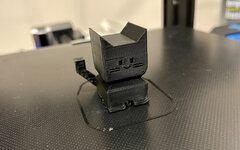
Parts of it were good and parts were bad. The bottom has warping (his little paws pulling away from the bed), and so do some of the corners and tail.
And there's one Y-axis layer shift just above the eyes.
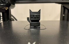
The photo makes it look messier than it is, but here you can see the paw warping.
On the plus side, most of the surfaces looked pretty nice and the head and ears were nice and sharp. And he was quite dimensionally accurate.

That's all I've got for now.
I don't think 0.2V is enough to cause overheating, so I'm starting to suspect that the stepper may just be bad. A partially shorted coil in the stepper will create heat, make movements non-linear and cause loss of power. This kind of stepper has two coils with 4 wires. You can unplug the connector and measure the resistance (impedance) of the coils independently with your multimeter (using the Ohms position.) Pick any two pins on the connector, if they are a pair you will get a reading, if they are different coils it will measure open (OL) so chose one of the other pins with one of the multimeter leads until you get a reading. Then measure the remaining two wires as they will be the other coil. The resistance of the two coils should be the same, and they should match any of the other (identical) motors (test a different motor as a 'known good' baseline.) A shorted coil should show up doing this test, and would presumably be grounds to have the stepper replaced under warranty.
Pimping your 3D ride is part of the fun, and the silent board is a godsend, you have no idea how bad the originals sounded. It really does remind me of the PC golden ages when we lovingly hand built our rigs from the best parts available. In a few years everyone will just buy the Apple iExtruder and have a incredibly trouble free experience, but what's the fun of that*?
*I will almost certainly be the first in line to buy one and never look back, but I'm going to flex my street cred for now.
Pimping your 3D ride is part of the fun, and the silent board is a godsend, you have no idea how bad the originals sounded. It really does remind me of the PC golden ages when we lovingly hand built our rigs from the best parts available. In a few years everyone will just buy the Apple iExtruder and have a incredibly trouble free experience, but what's the fun of that*?
*I will almost certainly be the first in line to buy one and never look back, but I'm going to flex my street cred for now.
OP
nicholam77
Well-known member
A shorted coil should show up doing this test, and would presumably be grounds to have the stepper replaced under warranty.
Thanks for walking me through it. I'll report back
Klokwerk
Well-known member
The joys of 3d printing!
This is going to date me. I supported AutoCAD 10 up to AutoCAD 2000. I'd been drafting since jr high with T squares and protractors before learning CAD from some Martin Marietta engineers in Orlando, Fl in 1989. Haven't touched it much since changing gears in 2001. Maya was way after my time.What products did you do Autodesk support for? I've never used their stuff myself as I'm a video editor, but I'm fairly familiar with their offerings as my dad was an architect (now retired), and my work (video post-production) uses their Flame and Flare finishing software, as well as Maya etc.
OP
nicholam77
Well-known member
Some heavy fog this morning on the way to daycare drop off. I've probably long scared away the VW crowd with all the woodworking and house project posts, but thought it looked kinda neat so I snapped a pic!

Matt Johnson
Well-known member
Lighting & Reflection almost make look like Great Falls Green!Some heavy fog this morning on the way to daycare drop off. I've probably long scared away the VW crowd with all the woodworking and house project posts, but thought it looked kinda neat so I snapped a pic!
wreckdiver1321
Well-known member
Hey look at that, Nick seems to be a car guy! Who'd have thought? 
OP
nicholam77
Well-known member
Lighting & Reflection almost make look like Great Falls Green!
Yeah, you're right!
Hey look at that, Nick seems to be a car guy! Who'd have thought?
I am a "car guy". I put it in quotes because I'm not a big diy mechanic. I've done some light work and mods over the years but nothing major. But I do love cars and always have!
_____________________________________
Got my "precision" electronics screwdrivers from Amazon today. So tonight after kid bedtime I decided to mess with the vref settings on the Ender 3 motherboard.

It's a pain in the a$$ because the machine has to be upside down, in my lap, and the motherboard is unscrewed from the frame so somewhat loose, but with the way the wires are routed through the frame it can't come out easily without disconnecting everything. Which would be problematic. Plus Creality decided to hot glue all the connections.
Each stepper motor driver has a trim pot screw that can adjust the "vref" or voltage. I did this with the power off... so it was turn it on, check with the multimeter, turn off, make small adjustment, rinse and repeat. They are very sensitive, so just the smallest turn (like a couple degrees) makes a difference. Hard to dial in exactly. But I ended up lowering everything. Creality recommended values in black, my new values in red:
X 1.18 - 1.2. 1.158
Y 0.99 - 1.01 0.998
Z 1.18 - 1.2 1.177
E 1.38 - 1.4 1.336
So, fairly close to recommended values but a tick under.
@Bakafish I also tried to measure the resistance, but not 100% sure I did it correctly. For some reason it seemed to always give me a value no matter which two pins I used, and also it was hard to get the multimeter leads to make contact with the pins. But this is what I came up with:
Y-Motor 1.533
X-Motor 1.632
The Y and X motors are similarly sized, I assume they are the same part. I don't know what this means, maybe you can help interpret?
Anyways I printed another Calicat, and didn't even vent the motherboard this time.
MEOW!
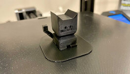
Still some issues with warping and cooling on this particular model, but... no layer shifts!!! Finally! It's only one print, but I'm cautiously optimistic. I'm hoping the rest I can dial in with slicer settings and some calibration (I haven't even checked e-steps yet).
Who knows if the layer shifts will come back again, but at least for the moment, I'm slightly less irritated with the machine.
Got my "precision" electronics screwdrivers from Amazon today.
You have no need for these, but they make non-conductive ceramic screwdrivers so you can adjust these kinds of pots 'live' and some people are brave enough to use a conductive driver with one of their test leads alligator clipped to it to do 'real time' adjustments.
I also tried to measure the resistance, but not 100% sure I did it correctly. For some reason it seemed to always give me a value no matter which two pins I used, and also it was hard to get the multimeter leads to make contact with the pins. But this is what I came up with:
Y-Motor 1.533
X-Motor 1.632
Well you really shouldn't get any reading between the two coils with the motor unplugged from the board, if you really are seeing resistance between all the pins then what it is saying is that your two coils are internally shorted (which is BAD.) So I took a closer look at mine and noticed that mine use a 6 pin connector (although only 4 pins are used, you can see where the 4 wires are located on the connector you removed) and I am measuring ~2.9 Ohms on each coil and fully open (OL) between any of the pins of the two coils. Assuming they are still using the same motors (very likely) you can measure coil A between pins 1&4 and coil B on pins and 3&6. Those two sets of pins should be completely isolated from each other in order to work properly. If you also see continuity between pin 1 and "3&6" from the other coil then there is an internal short, and the voltage intended for the opposite coils will be interacting and the stepper is going to behave erratically and likely overheat.
Last edited:
OP
nicholam77
Well-known member
Assuming they are still using the same motors (very likely) you can measure coil A between pins 1&4 and coil B on pins and 3&6. Those two sets of pins should be completely isolated from each other in order to work properly.
Dumb question but I was trying to measure the connector pins (wire that goes back to the motherboard), not the pins on the motor. I take it from your comment I should be placing the multimeter leads on the motor pins? (shows what I know about electricity!)
OP
nicholam77
Well-known member
XMAS Picture Frames — Part 1
So... I'm in a tight spot. Very last minute. My wife wanted some "baby footprint" framed prints for XMAS. We actually got one for our daughter a long time ago but they printed it not true-to-life size and I never liked the font etc. I have enough Photoshop skills to do a proper layout so I told her I would make them look good and 1:1 scale for both kids, vs. use a service. All good on that front. But when looking at frames, I just couldn't justify the price. $50-70 a frame for hardwood, and not my style. I can make a good picture frame. So I decided I would make them.
Then... life happened. Work. Multiple weekends alone with a 3-yr-old and a 4-month old due to my wife's work schedule. The holidays have creeped up way too fast. So here's where I'm left, trying to knock out some last minute frames!!
I had no time to go to the store for wood, so I arranged with my dad to "borrow" some of the cherry for his pantry project.
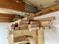
I picked the most warped board that I thought might not be usable for cabinet rails and stiles, and ripped it.

This was an edge cut, but anyone else get annoyed with the lack of overhead dust collection on the table saw?
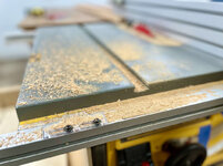
Did I mention it's a nice balmy 13° F outside?

Moving on. Cherry always seems to burn on my table saw so I planed out some of the burn marks.

I rarely use these clamps (they are Chinese knock-off of the Festool Clamping Elements), but when needed they are handy.


I really need a sharpening setup and some more hand tools and to make some boxes or something. Using a plane even with my novice skills is so satisfying.
I cut the rabbet for the frame and then cut the long boards into rough pieces. Used the new crosscut sled for this.
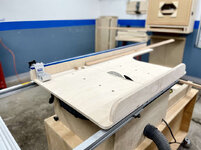
Having the Kreg stop is nice.
To cut the miters I use this William Ng style miter jig:

It doesn't have repeatability and is sort of a PITA, but it is pretty dang accurate and gets the job done.
Glued these bad boyz up, painters tape FTW.


My beloved Woodpeckers TS-3 is used to lay out the splines.
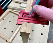
Not 100% necessary except it gives a visual representation of proportion, and I can put a piece of tape to help me set the blade height to cut them.
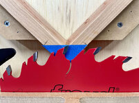
This is a new blade to me. A Freud FTG (Flat Top Grind) 24-tooth full-kerf rip. Should leave some nice and square splines.
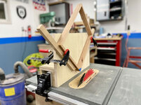
The spline jig I used is an old one, one of the first jigs I've made. It's far from my best work, but again, it gets the job done.
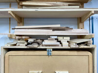
Since I'm in a pinch and building these from materials on hand, I searched my small piece scrapes and found some "1/8" maple stock for the splines. I knew I kept this stuff around for something!
Splines cut:

Now here's where I ran into a problem. 1/8" blade, 1/8" maple stock, you'd think it would be fine, right? Nah... the maple is about .02mm too thick. And yes that's too much where it won't slide in nicely.
So now I have to figure out how to thickness them. Or adjust all the spline cuts... but not too much! In the past I've just used an orbital sander to bring the spline thickness down, but I did that before I cut them into itty-bitty-triangles. Hand sanding is going to be a lot of effort. Not sure what else to do, though. Any suggestions? Buy a thickness planer?
Man I forgot how many steps are in picture frames. I have full week of work and up against the clock.

So... I'm in a tight spot. Very last minute. My wife wanted some "baby footprint" framed prints for XMAS. We actually got one for our daughter a long time ago but they printed it not true-to-life size and I never liked the font etc. I have enough Photoshop skills to do a proper layout so I told her I would make them look good and 1:1 scale for both kids, vs. use a service. All good on that front. But when looking at frames, I just couldn't justify the price. $50-70 a frame for hardwood, and not my style. I can make a good picture frame. So I decided I would make them.
Then... life happened. Work. Multiple weekends alone with a 3-yr-old and a 4-month old due to my wife's work schedule. The holidays have creeped up way too fast. So here's where I'm left, trying to knock out some last minute frames!!
I had no time to go to the store for wood, so I arranged with my dad to "borrow" some of the cherry for his pantry project.
I picked the most warped board that I thought might not be usable for cabinet rails and stiles, and ripped it.
This was an edge cut, but anyone else get annoyed with the lack of overhead dust collection on the table saw?
Did I mention it's a nice balmy 13° F outside?
Moving on. Cherry always seems to burn on my table saw so I planed out some of the burn marks.
I rarely use these clamps (they are Chinese knock-off of the Festool Clamping Elements), but when needed they are handy.
I really need a sharpening setup and some more hand tools and to make some boxes or something. Using a plane even with my novice skills is so satisfying.
I cut the rabbet for the frame and then cut the long boards into rough pieces. Used the new crosscut sled for this.
Having the Kreg stop is nice.
To cut the miters I use this William Ng style miter jig:
It doesn't have repeatability and is sort of a PITA, but it is pretty dang accurate and gets the job done.
Glued these bad boyz up, painters tape FTW.
My beloved Woodpeckers TS-3 is used to lay out the splines.
Not 100% necessary except it gives a visual representation of proportion, and I can put a piece of tape to help me set the blade height to cut them.
This is a new blade to me. A Freud FTG (Flat Top Grind) 24-tooth full-kerf rip. Should leave some nice and square splines.
The spline jig I used is an old one, one of the first jigs I've made. It's far from my best work, but again, it gets the job done.
Since I'm in a pinch and building these from materials on hand, I searched my small piece scrapes and found some "1/8" maple stock for the splines. I knew I kept this stuff around for something!
Splines cut:
Now here's where I ran into a problem. 1/8" blade, 1/8" maple stock, you'd think it would be fine, right? Nah... the maple is about .02mm too thick. And yes that's too much where it won't slide in nicely.
So now I have to figure out how to thickness them. Or adjust all the spline cuts... but not too much! In the past I've just used an orbital sander to bring the spline thickness down, but I did that before I cut them into itty-bitty-triangles. Hand sanding is going to be a lot of effort. Not sure what else to do, though. Any suggestions? Buy a thickness planer?
Man I forgot how many steps are in picture frames. I have full week of work and up against the clock.
Jeff Ivers
Well-known member
Thickness planer won't work on those small pieces - unless you make a jig. How about laying them on a belt sander for a bit?
That explains the unexpected readings.Dumb question but I was trying to measure the connector pins (wire that goes back to the motherboard), not the pins on the motor. I take it from your comment I should be placing the multimeter leads on the motor pins? (shows what I know about electricity!)
Yes, we are trying to establish the motor's health, so unplug the connector from the bottom side of the motor (gently pull the plastic plug out, it is a friction fit) and test the resistance between the small pins in the jack located there and compare the results to outlined in my previous post. You should only need to test the Y motor, since we can use my motor's test results (2.9 Ohms) as the baseline.They are a hidden piece and need space for a good glue line. Some aggressive sandpaper taped to your bench or on an Orbital sander held gently upside down in a vice (since the texture will help with the glue) and just lightly pass both sides by hand. Don't overthink it or use bladed tools when you can avoid it.So now I have to figure out how to thickness them. Or adjust all the spline cuts... but not too much! In the past I've just used an orbital sander to bring the spline thickness down, but I did that before I cut them into itty-bitty-triangles. Hand sanding is going to be a lot of effort. Not sure what else to do, though. Any suggestions? Buy a thickness planer?
M-technik-3
Well-known member
Maybe it's time you started a Youtube channel to get some sponsorship or join PBS. You have always got some neat project going, thanks for continuing to share.