
You are using an out of date browser. It may not display this or other websites correctly.
You should upgrade or use an alternative browser.
You should upgrade or use an alternative browser.
One year later 40'x80'
- Thread starter fnieto
- Start date
Mac and Mike,
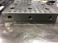
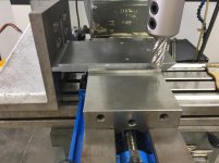
Here are the fixture plate dimensions:
1.5" thick x 8" x 10".
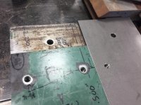
The small tapped holes (3/8"-16) are .500" OC from the 8" side and .750" OC to each other.
From the 10" edge they are 1" on OC. Theres 100 total for this size plate.
The eight larger perimeter holes measure .750" and have a .500" counterbore and are drilled/tapped for a 1/2"-13.
The center hole measures 1".
Backside is identical with exception to the center hole, It measures 1.5" and has a .500" deep counterbore.
The holes on all four edges are 1/2"-13 and line up with the larger perimeter holes.
First photo, L/R side measure 10" and shows the 1" center hole.
Second photo, is the 10" edge.
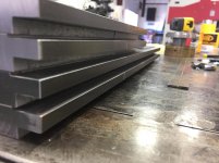
Third photo, id the 8" edge.
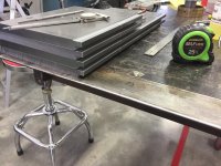
Last photo shows the larger hole on opposite side of fixture.
This particular fixture plate is hardened and ground.
Hope this helps.
Merry Christmas,
Paco
Here are the fixture plate dimensions:
1.5" thick x 8" x 10".
The small tapped holes (3/8"-16) are .500" OC from the 8" side and .750" OC to each other.
From the 10" edge they are 1" on OC. Theres 100 total for this size plate.
The eight larger perimeter holes measure .750" and have a .500" counterbore and are drilled/tapped for a 1/2"-13.
The center hole measures 1".
Backside is identical with exception to the center hole, It measures 1.5" and has a .500" deep counterbore.
The holes on all four edges are 1/2"-13 and line up with the larger perimeter holes.
First photo, L/R side measure 10" and shows the 1" center hole.
Second photo, is the 10" edge.
Third photo, id the 8" edge.
Last photo shows the larger hole on opposite side of fixture.
This particular fixture plate is hardened and ground.
Hope this helps.
Merry Christmas,
Paco
Attachments


adbanshee
Active member
Great shop, great work, great thread, I can't wait for more! Have a merry Christmas and a happy new year!
David
David
rmack898
Well-known member
Thanks Paco,
I'll have to look around for a piece of steel on my next trip to the supplier. I think this will be going to the top of my list for spare time projects.
Have a very Merry Christmas.
I'll have to look around for a piece of steel on my next trip to the supplier. I think this will be going to the top of my list for spare time projects.
Have a very Merry Christmas.
Thanks Paco,
I'll have to look around for a piece of steel on my next trip to the supplier. I think this will be going to the top of my list for spare time projects.
Have a very Merry Christmas.
Your very welcome Mac,
You'll use the heck out of the jig plate i'm sure.
Have a great New Year!
Paco
zmotorsports
ALLIANCE MEMBER
Thanks for the pictures and dimensions Paco.
Like Mac, I'm gonna have to make this a shop project at some point in time.
Like Mac, I'm gonna have to make this a shop project at some point in time.
zmotorsports
ALLIANCE MEMBER
The jig plate will compliment your tooling Mike, especially your press.
Happy New Year Mike.
Paco
Thanks Paco.
You have a very Happy New Year as well my friend.
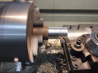
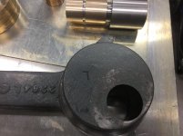
Made another press tool for the link handle bushings. I used an old bushing to make a two stage sleeve for pressing. They where turned down .045" smaller than the bushings being pressed. The short bushing ensures the tool fits into the bushing being pressed, then the second longer sleeve pushes the bushing out. Also had to repair the right pivot block, It was stuck due to mushrooming of the shaft end. Someone had hammered on this block at some point. Indicated the block end to the 4 jaw combination scroll/independent chuck. For those of you who have never used one, they are a real time saver when re-chucking multiple times. Its made by Bison and worth the money. Simply indicate your work piece using the independent jaw adjustments, then use the scroll to remove your work. re chuck using the scroll and the repeatability is dead on. I finished up the pivot blocks by facing off the hammer dings for a new look.
Attachments


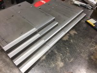
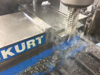
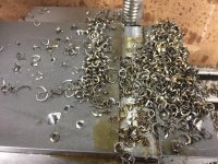
Next up was milling the first of three steps on the finger extensions.
Ordered a new 5 flute 1" medium rougher and a R8 holder. I took a .065" x .750" single pass to complete the first phase of the steps required. This end of the finger extensions fit into the upper clamp of the brake. The opposite side gets a .327" x .750" step to complete that end of the fingers. I plan on taking this in three passes. The final step is on the nose bar end and is .120"x 3" and secures the nose bar tooling. A total of 14 fingers are in the making (4-3",2-4", 4-5",4-6").
Ordered a new 5 flute 1" medium rougher and a R8 holder. I took a .065" x .750" single pass to complete the first phase of the steps required. This end of the finger extensions fit into the upper clamp of the brake. The opposite side gets a .327" x .750" step to complete that end of the fingers. I plan on taking this in three passes. The final step is on the nose bar end and is .120"x 3" and secures the nose bar tooling. A total of 14 fingers are in the making (4-3",2-4", 4-5",4-6").
Attachments


zmotorsports
ALLIANCE MEMBER
Very nice work indeed.
Love following this thread Paco.
Love following this thread Paco.
")
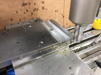
Got the second set of deeper steps cut on the fingers. This end indexes into the upper clamp bar of the brake. They do this by way of a track and allows for sliding fingers side to side for bending different widths. The OEM fit a bit on the loose side so I milled the new fingers to leave .378" from the OEM .350", the track measures .380". I decided to take the cut in a single pass in the Y axis using the power feed on the Lagun PhotoTrac. I locked down the X axis and knee and feed all 14 fingers without any drama.
Still have one more operation to complete the fingers. Its the nose bar step under the fingers that secure the nose bar dies. It's .125" deep and 2.250 wide.
For the .300"x .625" cut, the 1" cobalt rougher was turning 400 RPM and feed at 8 IPM with a little oil. Very nice surface finish with only slight file work to brake the edge.
Thanks for stopping by.
Happy new year,
Paco
Attachments

zmotorsports
ALLIANCE MEMBER
I couldn't agree more Paco.
I wish you and your family a safe, prosperous and Happy New Year as well my friend.
I wish you and your family a safe, prosperous and Happy New Year as well my friend.
Toomanytools?
Well-known member
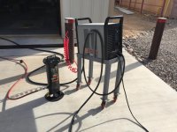
Tombstone are tried and true. I learned to arc weld with one back in 78. Hard to beat a transformer machine. I'll let you in on a little secret, I own a Lincoln weld pac 100 110 mig loaded with 10# spool of flux core. I've owned this machine since 1992 and have ran countless 10# spools with it. Miles of wire without a hiccup so long as you have a good power supply. I think I have only replaced the contact tip once or twice. Its my go to for small outdoor yard repair.
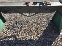
I fenced my entire property with this machine ( 2 days) but it was powered by a Miller bobcat 250. The nimble torch is great for stuff like this. The photo only shows one side of the property. It was over 800' in total. The first 110 mig I purchased was a Miller Cricket back in 89, that machine was a POS. The new Lincoln Power Migs are pretty darn nice.
Ok you can't post a picture of the fence and don't give us any details.
Looks like a 4x4 metal post with steel drill pipe welded to the sides. The paint looks pretty good how was that done? I'm in Washington state so setting a metal post in the ground makes me think it will rust away, probably not on my lifetime though.
Nice work
Haha, my point was the 110 Lincoln and its capabilities. The fence was built in 2000-2001 to keep wondering cows out. I recently repainted using oil base and a 4" roller.
As for the fence, The posts are 1/8" x 4" x 4" with exception to the hinge posts and corners (.250" wall)l. The pipe is sprinkler pipe used in commercial fire protection and came in 24' lengths (10 gauge x 1-7/8"). I made two posts jigs that snapped in place that supported the horizontal pipe for tacking. Each post jig allowed for placement of the pipe on both sides of the post, so when you moved on you simply "leap forged" as you progressed. The jigs eliminated any required measuring so long as all the post heights where the same elevation.
Did this answer you fence question.
Toomanytools?
Well-known member
Yes it did thanks
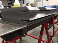
More on the D&K finger brake.
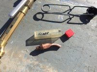
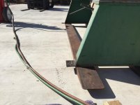
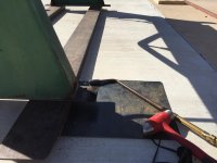
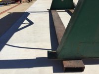
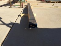
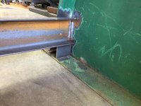
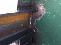
The units base leveling pads where bent and the 3/4" bracing rods where badly damaged and required removal. The unit was move outside for this dirty hot work and the weather was beautiful in the 70's.
A #10 rosebud was used to heat the bent leveling pads and returned to its original condition.
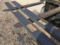
The upper clamp was removed in preparation for blasting, and the bracing rods where torched off using a scarfing tip making the final grinding minimal.
Next up will be fabricating fork pockets to allow for safe moving as the assembled unit is very top heavy and a PITA to move. At times I need to rearrange the floorspace for different production runs and I don't think a brake should be on casters like other machines in the shop.
The units base leveling pads where bent and the 3/4" bracing rods where badly damaged and required removal. The unit was move outside for this dirty hot work and the weather was beautiful in the 70's.
A #10 rosebud was used to heat the bent leveling pads and returned to its original condition.
The upper clamp was removed in preparation for blasting, and the bracing rods where torched off using a scarfing tip making the final grinding minimal.
Next up will be fabricating fork pockets to allow for safe moving as the assembled unit is very top heavy and a PITA to move. At times I need to rearrange the floorspace for different production runs and I don't think a brake should be on casters like other machines in the shop.
Attachments


Mike.ASC
Well-known member
Well done sir.
zmotorsports
ALLIANCE MEMBER
Very nice Paco.
Amazing work as usual.
Amazing work as usual.
rmack898
Well-known member
Nice job Paco, that brake will come in handy and you'll wonder how you ever got along with out it.
I stopped putting things on wheels quite a few years ago, now everything in the shop has fork pockets. I find moving things with a pallet jack much easier than if it had wheels.
I stopped putting things on wheels quite a few years ago, now everything in the shop has fork pockets. I find moving things with a pallet jack much easier than if it had wheels.
Thanks Mike (both of you). Getting closer by the day but still a bit away from blasting/painting.
The New Lathe arrives in LA today but need to clear customs before she comes home. Pretty excited. My old Chinese lathe served me well but the new one made by SunMaster is super nice.
Check out the ****:
Peace!
I should add Sun Master builds the Kent RML and the Acra 1640TE (the one I'm getting).
I will post all the modifications and enhancements as I go along.
Paco
The New Lathe arrives in LA today but need to clear customs before she comes home. Pretty excited. My old Chinese lathe served me well but the new one made by SunMaster is super nice.
Check out the ****:
I should add Sun Master builds the Kent RML and the Acra 1640TE (the one I'm getting).
I will post all the modifications and enhancements as I go along.
Paco
Last edited:
Nice job Paco, that brake will come in handy and you'll wonder how you ever got along with out it.
I stopped putting things on wheels quite a few years ago, now everything in the shop has fork pockets. I find moving things with a pallet jack much easier than if it had wheels.
Thanks Mack,
I'm considering doing something similar to the 40 Drake vertical band saw weighing in at 2500 lbs. I've have a 8' Whitney apron brake that has served me well, but useless for folding boxes. Appreciate your visit and comments.
Paco
zmotorsports
ALLIANCE MEMBER
Thanks Mike (both of you). Getting closer by the day but still a bit away from blasting/painting.
The New Lathe arrives in LA today but need to clear customs before she comes home. Pretty excited. My old Chinese lathe served me well but the new one made by SunMaster is super nice.
Check out the ****:Peace!
I should add Sun Master builds the Kent RML and the Acra 1640TE (the one I'm getting).
I will post all the modifications and enhancements as I go along.
Paco
Sounds nice. I guess I didn't realize you were getting rid of your Birmingham lathe and getting a new one.
What made you decide to give up the Birmingham? I thought it was a nice lathe, especially after all of the upgrades you did to it.
Sounds nice. I guess I didn't realize you were getting rid of your Birmingham lathe and getting a new one.
What made you decide to give up the Birmingham? I thought it was a nice lathe, especially after all of the upgrades you did to it.
Hey Mike,
The Birmingham is a nice machine (even before the modifications) and has served me well. My wife bought me the new machine for Christmas after overhearing me tell a friend a bigger spindle bore would be nice. She failed to realize all my tail stock tooling is 3 M/T and the bigger lathe uses 4 M/T tooling.
I will also need to change all the chuck mounting plates but I plan on machining those. The 1640 also weighs 1400 pounds more so I should be able to take much deeper cuts than the usual .080". It will get a Mark Jacobs control system much like the 1440 and a nicer DRO system. Should last me the remainder of my life god willing.
My old machine is for sale and asking $5K with limited tooling and a taper attachment. If no bites, I will give it to my son as a house/shop warming gift.

She still spoils me after 30 years of marriage.
I am a blessed man brother.
Paco
zmotorsports
ALLIANCE MEMBER
Hey Mike,
The Birmingham is a nice machine (even before the modifications) and has served me well. My wife bought me the new machine for Christmas after overhearing me tell a friend a bigger spindle bore would be nice. She failed to realize all my tail stock tooling is 3 M/T and the bigger lathe uses 4 M/T tooling.
I will also need to change all the chuck mounting plates but I plan on machining those. The 1640 also weighs 1400 pounds more so I should be able to take much deeper cuts than the usual .080". It will get a Mark Jacobs control system much like the 1440 and a nicer DRO system. Should last me the remainder of my life god willing.
My old machine is for sale and asking $5K with limited tooling and a taper attachment. If no bites, I will give it to my son as a house/shop warming gift.
She still spoils me after 30 years of marriage.
I am a blessed man brother.
Paco
That is awesome Paco. Glad to hear your wife still takes care of you and I will patiently await pictures of the new lathe.
New lathe cleared customs and is being tested. Got a couple of short (very short) videos from the dealer today.
The machine is sold by Acra machine and is a 1640TE.
The first video demonstrates the carriage feed/cross slide feed reversal feature.
This video demonstrates the 1800 PRM check.
Pretty excited to get her home for a full system makeover and DRO install.
The machine is sold by Acra machine and is a 1640TE.
The first video demonstrates the carriage feed/cross slide feed reversal feature.
Also completed the finger extensions. The last two operations where the cut a .125 depth x 2.5" step for the nose bar and clamp. I took a full depth cut using the same 1" 5 flute medium roughing end mill in three passes for each finger. The last operation was to break the sharp angle edge using a 7/16" four flute end mill at 1200 RPM and 10 IPM. It only required a .050" cut. Comparison with the only serviceable (green) finger was good to go. Getting close to sand blasting
Attachments


Worked on the top clamp adjusters. The right side had a bind when rotated and I suspected a bent screw. The handles where also fabricated at some point and less than ideal. Once I disassembled the screw jacks I was pleased to learn the bent sections where only on the portions the handles attached to. I was able to salvage both screw by cutting off the bent sections and drilling out the main screw body to receive a new machined pin. This was an interference fit that required heating to drive the new pins in. Tig welded the bevels then turned to fit the new design hand wheel. I have a design in mind and will tackle those later.
Attachments
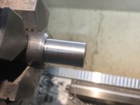

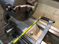


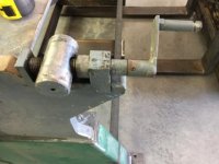
Here you can see the pin ready for pressing followed by welding and then turned.
The new wheel hubs will match the profile of the newly machined screws.
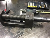
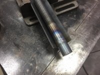
The black sharpie lines are reference of where the welds are. The bevels ensured plenty of weld remained after turning. Both pins turn true now and should adjust with lite effort. Overall a good solution to salvaging the two screws. Only used 5" of 1" CR round and saved a lot of time vs turning new screws.
The new wheel hubs will match the profile of the newly machined screws.
The black sharpie lines are reference of where the welds are. The bevels ensured plenty of weld remained after turning. Both pins turn true now and should adjust with lite effort. Overall a good solution to salvaging the two screws. Only used 5" of 1" CR round and saved a lot of time vs turning new screws.
Attachments


Last edited:
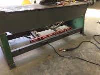
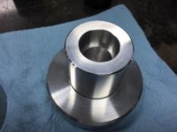
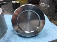
Had a couple of hours of shop time after a 24 hour shift. I turned one of two adjusting dials for the screw jacks to replace the hacked cranks someone had made.
I had 24" piece of 3" aluminum round bar in the scrap bin that worked out well.
Cut two pieces at 2-5/16" and face milled one end using a V-blosk to establish perpendicularity. This allowed me to chuck up against the face of the chuck and face the opposite end for parallelism with minimal waste. The dial was turned down to 1.600 OD x 1.500" L. Drilled to .750" and bored two profiles to match the shaft. I cut .001" oversize for a nice fit. The "suction Pop" was present when pulling apart. The face of the dial got a decorative profile to add a little personality.
The last photo shows the two cranks that where once used. The left crank was made using sloppy round tubing, angle and .375" round bar held in via roll pin.
Both cranks fit excessively sloppy on the once bent shafts.
Attachments


1/2 Cup
Member Emeritus
fnieto as always, beautiful workmanship..
1/2 Cup
Member Emeritus
Thank you 1/2 cup,
hope all is well in Aussie land.
All good only its a tad warm at the moment..