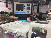
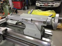
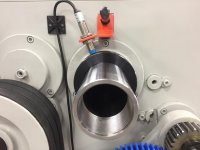
Well I decided to relocate the third scale from the compound to the tailstock (TS). After considerable consideration, I admitted to my self the TS application would be used far more than any vectoring/summing done by the compound. Besides a calculator would aid is any vectoring problems I may encounter. The ability to drill precise hole depths made more sense. The compound application would also require the cable to be hanging out in the "danger zone" and looped around around the front dial full time.
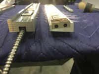
This was a costly decision on my part as the scale was previously cut to fit the 5" travel of the compound vs the 6" quill travel of the TS. A replacement scale cost me $145.
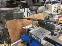
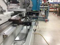
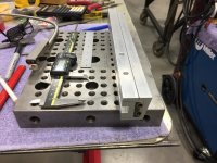
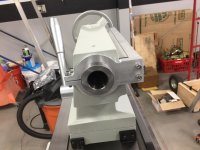
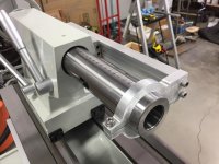
The TS body has a 9º taper so a piece of 5/8" x 1.5" aluminum bar stock was milled to provide the scale a vertical mounting surface.
The mill head was set for the 9º face mill pass.

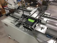
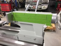
The bar stock was then milled for the scale to nest in. This design will make the scale static and the readhead dynamic when the TS quill is in travel.

Having the scale plumb will not only look better but will allow for the geometry of the readhead arm to line up better.

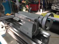
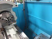
Befor I can design the readhead arm, I need to machine the quill clamp that the arm will attach to via two countersunk slotted holes for lateral fine adjustment. The arm will have a machine profile of the scale bracket. This should allow for a sliding track setup (I hope).
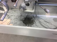
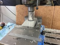
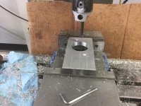
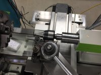
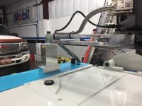
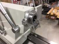
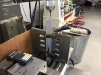
The material used for the quill clamp is 1/2" thick and will require profiling. The rear portion will have a slit of .120" and use a counterbored cap screw to clamp tight to the quill. the opposite end will be for the arm to mount. I used the largest annular cutter I have to save time in boring to size. I opted to over bore by .004" for a slip fit onto the quill. The .120" slit should allow for adequate clamping.

Boring provided a beautiful surface finish

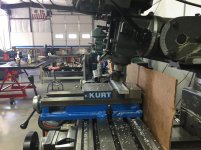
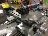
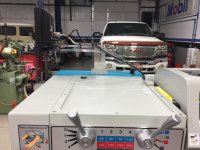
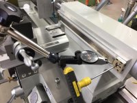
Heres where a long mill table is handy. The vise will remain trammed in place while a rotary supper spacer is setup for profiling the clamp. A co-axeal indicator was used to quickly find the center. The DRO was set to absolute zero on X/Y. The center was then offset for the end mill used and the rotary table was rotated taking notes on the degrees for full cut travels.
Used a three flute 7/16" end mill at 1500 RPM with low PSI air to clear the swarf and a little WD-40.

A final pass of .020" provided a nice finish

More to follow.
This was a costly decision on my part as the scale was previously cut to fit the 5" travel of the compound vs the 6" quill travel of the TS. A replacement scale cost me $145.
The TS body has a 9º taper so a piece of 5/8" x 1.5" aluminum bar stock was milled to provide the scale a vertical mounting surface.
The mill head was set for the 9º face mill pass.
The bar stock was then milled for the scale to nest in. This design will make the scale static and the readhead dynamic when the TS quill is in travel.
Having the scale plumb will not only look better but will allow for the geometry of the readhead arm to line up better.
Befor I can design the readhead arm, I need to machine the quill clamp that the arm will attach to via two countersunk slotted holes for lateral fine adjustment. The arm will have a machine profile of the scale bracket. This should allow for a sliding track setup (I hope).
The material used for the quill clamp is 1/2" thick and will require profiling. The rear portion will have a slit of .120" and use a counterbored cap screw to clamp tight to the quill. the opposite end will be for the arm to mount. I used the largest annular cutter I have to save time in boring to size. I opted to over bore by .004" for a slip fit onto the quill. The .120" slit should allow for adequate clamping.
Boring provided a beautiful surface finish
Heres where a long mill table is handy. The vise will remain trammed in place while a rotary supper spacer is setup for profiling the clamp. A co-axeal indicator was used to quickly find the center. The DRO was set to absolute zero on X/Y. The center was then offset for the end mill used and the rotary table was rotated taking notes on the degrees for full cut travels.
Used a three flute 7/16" end mill at 1500 RPM with low PSI air to clear the swarf and a little WD-40.
A final pass of .020" provided a nice finish
More to follow.


")