If you lift only sedans, coupes and pickup trucks, you could have a smaller raised ceiling area like a 6-8 foot opening that might not require as much structural reinforcement as raising the entire interior roof structure. If not using it as a 2 car anymore you could alternatively add a couple of posts on either side of the lift, but they can get in the way of you need a large area of open work space. I have a center post structural support but my lift fits on one side.


You are using an out of date browser. It may not display this or other websites correctly.
You should upgrade or use an alternative browser.
You should upgrade or use an alternative browser.
Raising garage ceiling questions
- Thread starter MikeC55
- Start date
p00p
Well-known member
could removing the concrete slab, digging it out deep enough to achieve the desired ceiling height & repouring the slab be an option?
The additional thickness of concrete might be another positive, in order to support a lift.
The additional thickness of concrete might be another positive, in order to support a lift.
Innovate1
Well-known member
That's a poor design. Very high tie between sides isn't going to keep the bottoms from spreading. And the tie is in the middle of the truss section resulting in lots of bending force. Trusses tie things together at the joints so the links only have tension or compression (except for the top cord roof and bottom ceiling). I get that you want to reinforce the rafters but you can't forget about spreading force. Take a look at scissor truss and cambered truss layout here (just a random site that shows basic truss types):This is what I was thinking for an inverted truss. I drew it with 2 x 4 but it could just as easily be 2 x 6. The trick would be properly tying the members together. I think you would need a metal plate to bolt the pieces together. I think this would need an engineer and maybe a truss company to build them
https://www.zeelandlumber.com/most-common-types-of-roof-trusses/
General rule of thumb for scissor truss is the bottom links should be half or less slope than the roof. Less slope is stronger. I would think he same would apply to the lower angled parts on the cambered.
Truss companies can design how to add the parts to your existing structure. May have to call around to find one that will do that as I suspect most just want to design trusses to sell. They should also define how to connect the joints. You could do the work but they may want to. Joints could be done with plywood.
Innovate1
Well-known member
If you google "site built roof trusses" you will find companies that will do the engineering. I also found this discussion you might find helpful.
https://www.finehomebuilding.com/forum/site-built-vs-premade-trusses
https://www.finehomebuilding.com/forum/site-built-vs-premade-trusses
Innovate1
Well-known member
Here's another link
https://forums.jlconline.com/forums...4974-site-built-plywood-gusseted-wood-trusses
I know metal plates and bolts seem great but I think reality is you need several smaller bolts to spread the load out on the wood. I read somewhere a study of bolt connections to wood and smaller bolts held more than big bolts IIRC so sometimes things are counter intuitive. Many nails with plywood gussets also spread out the load and would be just as good if properly sized and nailed and easier than all the drilling.
https://forums.jlconline.com/forums...4974-site-built-plywood-gusseted-wood-trusses
I know metal plates and bolts seem great but I think reality is you need several smaller bolts to spread the load out on the wood. I read somewhere a study of bolt connections to wood and smaller bolts held more than big bolts IIRC so sometimes things are counter intuitive. Many nails with plywood gussets also spread out the load and would be just as good if properly sized and nailed and easier than all the drilling.
billconner
Well-known member
It's a very interesting thread to me. The kind of problem I enjoy noodling on. I think sistering 2x10s to rafters with raised ties is a dead simple answer, but concerned with how shallow they ate sitting on top plate. The existing 2x6 probably provides enough shear strength. Timberlocks up through plates into rafters and ties would be my choice over Simpson Strong tie.
I still think the horizontal beam and just removing ties in high bay has legs. Was imagining a 2x12 or maybe an LVL flat, top flush with top plate, and a steel angle connecting the ends of that beam across the garage, anchored to a tie for support. Some details to be worked out but seems doable.
I still think the horizontal beam and just removing ties in high bay has legs. Was imagining a 2x12 or maybe an LVL flat, top flush with top plate, and a steel angle connecting the ends of that beam across the garage, anchored to a tie for support. Some details to be worked out but seems doable.
Innovate1
Well-known member
I was surprised to find truss calculators on line. EDIT: Looks like this one is limited enough for the free version to not be useful - I reached the limit when applying the load to the roof and maxed out at two members. We did calculations like this in first year engineering - it's just tedious to do by hand.
Here is one (default is metric but can be changed in settings):
https://skyciv.com/free-truss-calculator/
Once you have the stresses in individual members you could enter that into something like the western wood products assn calculator to determine size of members. I am guessing 2 x 4s would be adequate.
Here is one (default is metric but can be changed in settings):
https://skyciv.com/free-truss-calculator/
Once you have the stresses in individual members you could enter that into something like the western wood products assn calculator to determine size of members. I am guessing 2 x 4s would be adequate.
Last edited:
CraigStu
Well-known member
I just looked through the thread again and had a thought similar to pbon and billconner. The existing rafters are on 4ft centers so, if one is removed, you now have an 8ft long area available for the roof of a car to fit in. I can't tell for sure but it seems that if you remove the one that is closest to center of the garage it might be all you need. Thinking that reinforcing for just one missing board would be a lot easier than reinforcing the whole length of the garage.
firebirdparts
Well-known member
That's not a truss; it's a frame. Weak as a kitten as drawn. In steel, of sufficient size of course, that would work. You can get enough strength with steel in less space, basically.This is what I was thinking for an inverted truss. I drew it with 2 x 4 but it could just as easily be 2 x 6. The trick would be properly tying the members together. I think you would need a metal plate to bolt the pieces together. I think this would need an engineer and maybe a truss company to build them
I'm not sure I follow what you mean here Bill; "I still think the horizontal beam and just removing ties in high bay has legs. Was imagining a 2x12 or maybe an LVL flat, top flush with top plate, and a steel angle connecting the ends of that beam across the garage, anchored to a tie for support."
Also, when you say "I think sistering 2x10s to rafters with raised ties is a dead simple answer, but concerned with how shallow they ate sitting on top plate", you are concerned with how the sistered 2 x 10s would rest on the top plate of wall (because of how they would be trimmed to fit under the roof sheathing)?
Also, when you say "I think sistering 2x10s to rafters with raised ties is a dead simple answer, but concerned with how shallow they ate sitting on top plate", you are concerned with how the sistered 2 x 10s would rest on the top plate of wall (because of how they would be trimmed to fit under the roof sheathing)?
Innovate, in your comment "Very high tie between sides isn't going to keep the bottoms from spreading. And the tie is in the middle of the truss section resulting in lots of bending force. Trusses tie things together at the joints so the links only have tension or compression (except for the top cord roof and bottom ceiling).", the short horizontal section between the inverted trusses was only to support insulation and ceiling material. I didn't mean it be structural.
When you mention, "rule of thumb for scissor truss is the bottom links should be half or less slope than the roof. Less slope is stronger. I would think he same would apply to the lower angled parts on the cambered." On my inverted truss, one bottom link is horizontal but the other is has a greater slope than the roof - this is what is poor about the design?
When you mention, "rule of thumb for scissor truss is the bottom links should be half or less slope than the roof. Less slope is stronger. I would think he same would apply to the lower angled parts on the cambered." On my inverted truss, one bottom link is horizontal but the other is has a greater slope than the roof - this is what is poor about the design?
Latka Gravas
New member
- Joined
- Jul 5, 2022
- Messages
- 4
Prior to my present occupation I worked as a carpenter for more years than I care to remember. Based on my knowledge and past experience, if this were my garage, the easiest and cheapest way to maximize headroom would be to install a structural ridge beam under the existing ridge board. You might have to remove the exterior siding on one gable end and cut a hole in the sheathing in order to insert the new ridge beam. Install some temporary rafter ties high enough up to give the beam something to rest on while you push it in to the building. The biggest downside to that option is that it would require a piece of equipment (crane, telehandler, etc.) in order to install it. Another option, and the one that I would go with since the garage is a square, would be to install it by lifting it up and over the existing rafter ties and jacking it into place from inside the building. Obviously you would also have to run vertical support columns to the foundation. You can avoid the building inspector by have a structural engineer size the beam for you. A couple of LVLs bolted together, with possibly a steel flitch plate in between them, should more than carry the load of the existing roof as well as any snow load. Edit to add that you could get all of your holes drilled while the beam is on the ground and then put it up in separate pieces and bolt it all together while it’s in place. BTDT many times. If you’re doing this yourself it will require some willing hands to help with it. One more edit. When you put the center door in, and this should go without say but I’ll say it anyway, you’ll have to make sure that your header will support the extra load of the ridge beam.
Here is an article from the Journal of Light Construction that tells about structural ridge beams.
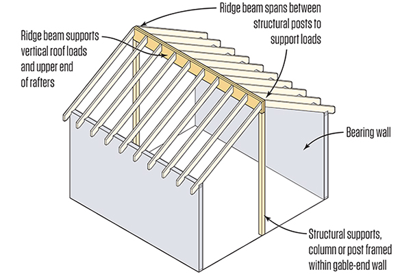
Here is an article from the Journal of Light Construction that tells about structural ridge beams.
Ridge Beams vs. Ridge Boards
When renovating an attic, be sure you understand the difference between ridge beams and ridge boards. One is a structural member, and one is not.
www.jlconline.com
Last edited:
Latka Gravas
New member
- Joined
- Jul 5, 2022
- Messages
- 4
One other thing that I’ll throw in here. If the budget allows for it, instead of LVLs, you could install a steel wide flange/ I beam sized so that you could install a 1/2 ton, or even a 1 ton, hoist on a trolly that would go the entire length of your garage.
Innovate1
Well-known member
Perhaps you didn't mean the high tie to be structural and only support the ceiling but it is the only thing keeping the ends sitting on the walls from spreading (and pushing the top of the walls out). That's the whole point of the ceiling joists where they are or if they are raised. So it is structural. And inadequate. Sorry to be blunt but it is. Here's how I envision an implementation that might work. Sort of inverted trusses if you want to think of it that way but really cambered style. Also sort of like scissor truss but with flat mid section. The main difference from what you posted is that the cross tie is much lower AND it attaches where other members attach so doesn't put bending strain on other links in the truss. I figured 8' wide raised middle section at 2' above current joist location. Ignore the numbers - it's from the truss calc site I posted earlier. The sections for half slope are links 4 and 11 - they should be half the slope or less or links 1 and 9. In this diagram they are 3:12 and just half of your 6:12 roof.Innovate, in your comment "Very high tie between sides isn't going to keep the bottoms from spreading. And the tie is in the middle of the truss section resulting in lots of bending force. Trusses tie things together at the joints so the links only have tension or compression (except for the top cord roof and bottom ceiling).", the short horizontal section between the inverted trusses was only to support insulation and ceiling material. I didn't mean it be structural.
When you mention, "rule of thumb for scissor truss is the bottom links should be half or less slope than the roof. Less slope is stronger. I would think he same would apply to the lower angled parts on the cambered." On my inverted truss, one bottom link is horizontal but the other is has a greater slope than the roof - this is what is poor about the design?

Innovate1
Well-known member
True, but you still need to hold up that beam with something at the ends. Just saying. And its a lot of force at the ends to hold up the whole span.One other thing that I’ll throw in here. If the budget allows for it, instead of LVLs, you could install a steel wide flange/ I beam sized so that you could install a 1/2 ton, or even a 1 ton, hoist on a trolly that would go the entire length of your garage.
billconner
Well-known member
I was tryin to summarize. On sistering 2x10s to existing 2x6s and raising rafter ties, I was a little concerned by how little 2x10 is left, but I think sistered to 2x6, together they give you enough shear strength. It would be nice if you could widen top plate so more of sawn end of 2x10 was supported. Anchor a 4x4 or even 2x4 flat against top plate and/or maybe cleat the bottom of the 2x10. Just imagining max load causing 2x10 to split at the edge of top plate.I'm not sure I follow what you mean here Bill; "I still think the horizontal beam and just removing ties in high bay has legs. Was imagining a 2x12 or maybe an LVL flat, top flush with top plate, and a steel angle connecting the ends of that beam across the garage, anchored to a tie for support."
Also, when you say "I think sistering 2x10s to rafters with raised ties is a dead simple answer, but concerned with how shallow they ate sitting on top plate", you are concerned with how the sistered 2 x 10s would rest on the top plate of wall (because of how they would be trimmed to fit under the roof sheathing)?
The issue for the rafter ties is as you noted the walls spreading. The 2x6s are fine for roof load - empirically - if you don't raise the rafter tie. When I understood you were not raising all collar ties, but just a center 12' or less, I recalled you can prevent the walls spreading with a beam at top plate to resist the outward push of the rafters. So, move the center rafter ties into ends where they can stay at bottom, and put a beam - flat - horizontally at each top plate, and tie the opposite ends together. So no new materials except those two beams and two (steel) ties connecting the ends of the beams.
Simple vector problem to calculate outward force of rafters with maximum snow load, but at 8', a 2x12 would work I think. At 12' it might need an LVL - maybe a single 1 3/4 by nominal 12.
I like a solid steel piece for tension member (ties) because of problems of wood in tension and connections and shear. I thought a steel angle would anchor nicely across the horizontal face of a 2x12 or lvl, and the gravity load of the steel pieces could be easily supported by an existing adjacent rafter tie. You could use a steel rod or even a wire rope, but a tiny bit of stretch in that, plus temptation to pre stress too much, concerns me. And you could probably use wood to tie them, just overkill the connections.
I wish I was quick and able to sketch on my phone but alas, I'm not.
Just think of it as inserting a really stiff rectangular frame in place of removed rafter ties at the top plate. And keep ceiling and insulation materials as light as possible.
Is that clearer?
Denwood
Well-known member
2 pages of discussion where a properly ridge beam is all you need. I did this in my shop with about $600 of LVL (spec’d to my application by a local truss shop). Built in place, 4-6 hours of work. I created a 16ft loft for the lift.
Supporting the ridge beam is just two more LVLs across your shop at both ends. The cross support at one end is also the way to deal with a larger garage door for the OP as this LVL can be spec’d for this purpose.
My commercial building had two large areas where lofts were created by modifying trusses in place using stressed skin methods. The ridge beam is much easier and faster for a garage…and you get a full loft in that area. I used spray foam in the loft area for a non vented approach which also adds a lot of racking strength.
We have very high snow loads here.
Last edited:
billconner
Well-known member
Yes, what I inadequately tried to suggest. I was thinking what I called the king post - members 3 and 10 - could be perpendicular to rafter at center of rafter, and I thought raised rafter tie would cross truss and still anchor to 2x6. But it's two separate trusses replacing two rafters, and still needs the rafter tie.Perhaps you didn't mean the high tie to be structural and only support the ceiling but it is the only thing keeping the ends sitting on the walls from spreading (and pushing the top of the walls out). That's the whole point of the ceiling joists where they are or if they are raised. So it is structural. And inadequate. Sorry to be blunt but it is. Here's how I envision an implementation that might work. Sort of inverted trusses if you want to think of it that way but really cambered style. Also sort of like scissor truss but with flat mid section. The main difference from what you posted is that the cross tie is much lower AND it attaches where other members attach so doesn't put bending strain on other links in the truss. I figured 8' wide raised middle section at 2' above current joist location. Ignore the numbers - it's from the truss calc site I posted earlier. The sections for half slope are links 4 and 11 - they should be half the slope or less or links 1 and 9. In this diagram they are 3:12 and just half of your 6:12 roof.
But very helpful and good sketch and probably could work as you show. Thank you.
billconner
Well-known member
Structural ridge certainly works and is tried and true but seems like a lot more cost, especially getting into transferring load over garage door and at least investigating if the foundation can take those point loads. I'd guess at least 2 ply 14", maybe three ply ~$1000 at Menards.
And I'm biased toward designs where I can do everything myself, which means being able to lift each piece. It's how I save money.
PS Found a calculator - 24' LVL ridge beam, 30 pdf snow, 24' wide building - 4 no ply 14" (7") or 3 ply (5 1/4") 16". Somewhere in the 7000 pound range for columns at each end.
And I'm biased toward designs where I can do everything myself, which means being able to lift each piece. It's how I save money.
PS Found a calculator - 24' LVL ridge beam, 30 pdf snow, 24' wide building - 4 no ply 14" (7") or 3 ply (5 1/4") 16". Somewhere in the 7000 pound range for columns at each end.
Last edited:
Latka Gravas
New member
- Joined
- Jul 5, 2022
- Messages
- 4
Assuming that the garage is on a slab it can be engineered to spread the load over a wide area. Or just dig under the slab and pour a footer under where the load point will end up being. This is where a structural engineer comes into play. If the garage already has a foundation below the frost line then the odds are that it would more than carry the load of a steel beam. Again, this is if his budget allows it. It’s real easy to spend someone else’s money. LOLTrue, but you still need to hold up that beam with something at the ends. Just saying. And its a lot of force at the ends to hold up the whole span.
Latka Gravas
New member
- Joined
- Jul 5, 2022
- Messages
- 4
Structural ridge certainly works and is tried and true but seems like a lot more cost, especially getting into transferring load over garage door and at least investigating if the foundation can take those point loads. I'd guess at least 2 ply 14", maybe three ply ~$1000 at Menards.
And I'm biased toward designs where I can do everything myself, which means being able to lift each piece. It's how I save money.
PS Found a calculator - 24' LVL ridge beam, 30 pdf snow, 24' wide building - 4 no ply 14" (7") or 3 ply (5 1/4") 16". Somewhere in the 7000 pound range for columns at each end.
Innovate1
Well-known member
Bill can confirm but what I think he is suggesting is to put a beam at the top of the walls to resist the outward force. And that's the reason he wants to tie the rafter ends more securely to the top of the walls. That's one way to do it but it puts a lot of outward force on the walls that is transferred to the corners and results in racking force on the walls so you need to add cross ties at the ends since the existing walls aren't designed for that. It could be done that way but seems overly complicated to me and not the best solution but only my opinion.I was tryin to summarize. On sistering 2x10s to existing 2x6s and raising rafter ties, I was a little concerned by how little 2x10 is left, but I think sistered to 2x6, together they give you enough shear strength. It would be nice if you could widen top plate so more of sawn end of 2x10 was supported. Anchor a 4x4 or even 2x4 flat against top plate and/or maybe cleat the bottom of the 2x10. Just imagining max load causing 2x10 to split at the edge of top plate.
The issue for the rafter ties is as you noted the walls spreading. The 2x6s are fine for roof load - empirically - if you don't raise the rafter tie. When I understood you were not raising all collar ties, but just a center 12' or less, I recalled you can prevent the walls spreading with a beam at top plate to resist the outward push of the rafters. So, move the center rafter ties into ends where they can stay at bottom, and put a beam - flat - horizontally at each top plate, and tie the opposite ends together. So no new materials except those two beams and two (steel) ties connecting the ends of the beams.
Simple vector problem to calculate outward force of rafters with maximum snow load, but at 8', a 2x12 would work I think. At 12' it might need an LVL - maybe a single 1 3/4 by nominal 12.
I like a solid steel piece for tension member (ties) because of problems of wood in tension and connections and shear. I thought a steel angle would anchor nicely across the horizontal face of a 2x12 or lvl, and the gravity load of the steel pieces could be easily supported by an existing adjacent rafter tie. You could use a steel rod or even a wire rope, but a tiny bit of stretch in that, plus temptation to pre stress too much, concerns me. And you could probably use wood to tie them, just overkill the connections.
I wish I was quick and able to sketch on my phone but alas, I'm not.
Just think of it as inserting a really stiff rectangular frame in place of removed rafter ties at the top plate. And keep ceiling and insulation materials as light as possible.
Is that clearer?
banjopete
Well-known member

I raised the ceiling for a portion of my garage this way.
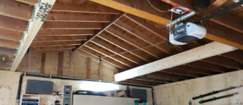
couple of built up beams from lumber, and one honker of a LVL beam, just throwing additional ideas in for you
billconner
Well-known member
Not at the corners - just an 8 to 12' section in middle. I didn't suggest the horizontal beam until I understood it wasn't 24' but half that or less.Bill can confirm but what I think he is suggesting is to put a beam at the top of the walls to resist the outward force. And that's the reason he wants to tie the rafter ends more securely to the top of the walls. That's one way to do it but it puts a lot of outward force on the walls that is transferred to the corners and results in racking force on the walls so you need to add cross ties at the ends since the existing walls aren't designed for that. It could be done that way but seems overly complicated to me and not the best solution but only my opinion.
billconner
Well-known member
Yes, another way, but pretty sure those B1 beams are doing same thing as my horizontal beams - resisting or transferring the forces trying to spread the walls apart.
I raised the ceiling for a portion of my garage this way.
couple of built up beams from lumber, and one honker of a LVL beam, just throwing additional ideas in for you
Innovate1
Well-known member
The B1 beams are oriented to handle mainly load in the vertical direction. Seems awfully stout for supporting weight and only holding up a ceiling. With that big of beam it will resist spreading at least somewhat but would be much stiffer in the direction if some were layed flat.Yes, another way, but pretty sure those B1 beams are doing same thing as my horizontal beams - resisting or transferring the forces trying to spread the walls apart.
Thanks guys, lots of ideas to think about. Bill, I'm still trying to fully understand your idea where you say "The issue for the rafter ties is as you noted the walls spreading. The 2x6s are fine for roof load - empirically - if you don't raise the rafter tie. When I understood you were not raising all collar ties, but just a center 12' or less, I recalled you can prevent the walls spreading with a beam at top plate to resist the outward push of the rafters. So, move the center rafter ties into ends where they can stay at bottom, and put a beam - flat - horizontally at each top plate, and tie the opposite ends together. So no new materials except those two beams and two (steel) ties connecting the ends of the beams." I think I get the horizontal beam attaching to top plate for resisting horizontal loads but not sure how I would attach it to top plate and should it also attach to the existing rafters at the bottom end? (or make sure the rafters are very well secured to the top plate/horizontal beam). If I planned it so the there would be existing rafter ties at each end of the raised section (2 x 8"), Could I just secure the horizontal bean to them or would it need reinforcing?
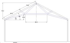
A structural ridge beam would be nice but that definitely moves it out of the DIY category for me. I did sketch up the improved inverted truss to scale (with 2 x 6 members). As long as I could adequately tie the connections together with glue/plywood screws... I am also assuming it would just be attached to one side of each rafter in the raised area (i.e., not butted in-plane to the rafter with plywood connection on each face). Would it make much difference?
A structural ridge beam would be nice but that definitely moves it out of the DIY category for me. I did sketch up the improved inverted truss to scale (with 2 x 6 members). As long as I could adequately tie the connections together with glue/plywood screws... I am also assuming it would just be attached to one side of each rafter in the raised area (i.e., not butted in-plane to the rafter with plywood connection on each face). Would it make much difference?
Attachments

Innovate1
Well-known member
If you go with the flat beam against the wall you are going to need to at least double the joist at the ends as it will be taking the spreading force of all the rafters in the opening. Tie the added beam to the existing top plate and rafters - could use angle brackets to nail or construction screw into both. I would run at least a 2 x 4 along the inner edge stood vertical to keep the larger beam from bowing up or down.
If you go with the truss I would keep all the members in the same plane and gusset with at least 1/2" plywood on both side and make the size generous. I am guessing at least a foot onto all members and nail every 2 inches staggering the lines to avoid splits. If you try to overlap the members you will have a difficult mess where you have 4 coming together. You could build it in place while the existing joists are in place although I might also lift some weight off things by jacking up the ridge beam just enough to take some load off but not move things much. Then when you have everything but the second side gussets at the ends take the joist out and apply the last gussets.
Of course this is all just estimation so you will have to do your own evaluation as to the adequacy of this. It looks like the members in the most tension will be the 3 pieces across the bottom so I would pay particular attention to those.
If you go with the truss I would keep all the members in the same plane and gusset with at least 1/2" plywood on both side and make the size generous. I am guessing at least a foot onto all members and nail every 2 inches staggering the lines to avoid splits. If you try to overlap the members you will have a difficult mess where you have 4 coming together. You could build it in place while the existing joists are in place although I might also lift some weight off things by jacking up the ridge beam just enough to take some load off but not move things much. Then when you have everything but the second side gussets at the ends take the joist out and apply the last gussets.
Of course this is all just estimation so you will have to do your own evaluation as to the adequacy of this. It looks like the members in the most tension will be the 3 pieces across the bottom so I would pay particular attention to those.
Denwood
Well-known member
Thanks guys, lots of ideas to think about. Bill, I'm still trying to fully understand your idea where you say "The issue for the rafter ties is as you noted the walls spreading. The 2x6s are fine for roof load - empirically - if you don't raise the rafter tie. When I understood you were not raising all collar ties, but just a center 12' or less, I recalled you can prevent the walls spreading with a beam at top plate to resist the outward push of the rafters. So, move the center rafter ties into ends where they can stay at bottom, and put a beam - flat - horizontally at each top plate, and tie the opposite ends together. So no new materials except those two beams and two (steel) ties connecting the ends of the beams." I think I get the horizontal beam attaching to top plate for resisting horizontal loads but not sure how I would attach it to top plate and should it also attach to the existing rafters at the bottom end? (or make sure the rafters are very well secured to the top plate/horizontal beam). If I planned it so the there would be existing rafter ties at each end of the raised section (2 x 8"), Could I just secure the horizontal bean to them or would it need reinforcing?
A structural ridge beam would be nice but that definitely moves it out of the DIY category for me. I did sketch up the improved inverted truss to scale (with 2 x 6 members). As long as I could adequately tie the connections together with glue/plywood screws... I am also assuming it would just be attached to one side of each rafter in the raised area (i.e., not butted in-plane to the rafter with plywood connection on each face). Would it make much difference?
I did my structural ridge beam 100% DIY. The LVLs are only 1 3/4" thick, so you can lift and build them in place. The only thing that was not DIY was the spec, provided for free by the truss company that sold me the LVL beams. Seriously, it took me only 4 hours...(with about 30 minutes of help from my brother to lift the ridge beam sections into place) to get the ridge and end support LVLs in place.
The difference (over @banjopete 's design) is that I was able to remove 16 feet of truss ties completely and use that area for extensive overhead storage (third pic).
@MikeC55 , your 18ft door issue can be addressed at the same time as your roof ridge as that beam would be needed to support one end of your ridge so can be spec'd to both serve as a an 18 foot door header and ridge support.
Check my thread page 1 and 2: https://www.garagejournal.com/forum/threads/woodys-works-garage.263351/
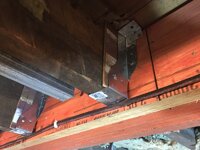
Note that the structure taking the ridge beam load down to the cross beams is a 4x4 flanked with two 2x4s and a 2x6 ... bonded with PL, and screwed with structural fasteners. Support was added after to take the "truss tie" LVL beams load down to the footing using triple 2x4s.
First pic is during construction, 2nd is final framing detail. This roof is crazy strong and has seen record snow fall levels this year (about 8 ft total) without a squeak.


Last edited:
Denwood, I see what you're getting at. The ridge beam doesn't have to go the full length of the garage; just the area you want to raise the ceiling. I also want to use the 8 foot ceiling areas for storage and so your plan makes sense there too. It looks like the trickiest part is getting the LVL rafter ties into place at the ends of raised section. How did you go about that? Since the start of the raised section would be 8' from the garage door, I don't think the header would have to be strengthened but I'll put an LVL in there anyway when retrofitting the 12' door (just to strengthen up to attic load capability)
billconner
Well-known member
Mike - I owe you a sketch - but the horizontal beam would be flush with the top plate in the same plane so to speak. I thought about pieces of ply spanning across beam and top plate or short pieces of two-by basically in same plane as existing rafter ties. Then each beam end would lap under a remaining rafter tie or doubled or tripled rafter tie.
I suggested some sort of steel tension member between ends of beams on opposite walls. The wood rafter ties could work. It's the connection that concerns me a little.
Let me try to do a sketch later today.
I suggested some sort of steel tension member between ends of beams on opposite walls. The wood rafter ties could work. It's the connection that concerns me a little.
Let me try to do a sketch later today.
Denwood
Well-known member
The LVL "rafter ties" were two x 1 3/4" x 12", with a cut at each end (also spec'd by the truss manufacturer) to match the roof slope. They were easy to angle in there over the wall top plate, one piece and one end at a time once a few truss ties were removed. I installed those first, then the ridge beam. You'll likely have to either add wall reinforcement or just add stud columns to the four ends of the LVL cross supports ("truss ties") to take load down to your footings. I did the cross beam LVL beams myself...just needed an extra hand to get the LVLs for the ridge support in place.Denwood, I see what you're getting at. The ridge beam doesn't have to go the full length of the garage; just the area you want to raise the ceiling. I also want to use the 8 foot ceiling areas for storage and so your plan makes sense there too. It looks like the trickiest part is getting the LVL rafter ties into place at the ends of raised section. How did you go about that? Since the start of the raised section would be 8' from the garage door, I don't think the header would have to be strengthened but I'll put an LVL in there anyway when retrofitting the 12' door (just to strengthen up to attic load capability)
It was a surprisingly easy/quick job. I should also note that I did this in summer, with no snow load present. The mod was 5 years or go, and this year saw record snow (in the order of 9 feet total) with zero issues.
The other unexpected impact of opening up the ceiling was a significant change in perceived shop size...it seems much larger when working in there than the 16x24 footprint would suggest.
This is the beam data, load etc. with the 3 1/2" x 3 1/2" bearing supports specified, cross beam end detail etc. Expected snow load for our area is 60lbs sq/ft, so for a 16x16 area, that's 15 360 lbs. The ridge/cross beam safety factor is over twice that at over 38 000 lbs.


Last edited:
Thanks Denwood, a couple more questions. The double ridge beam, did you double it on the ground and then hoist it up or pick them up one at a time and assemble in place? It seems like wrestling a double beam up there would be tough... Since my garage is closer to 24' wide, I'll have to see if a single LVL will do it on the ends of raised section. I was thinking to maybe combine this approach with the 'horizontal' beam idea at wall top plates form Bill. Just for a little extra insurance.
Denwood
Well-known member
Picked up one at a time and assembled in place. They are not crazy heavy at 16", so should be fine for two folks at 24'. You may need a 3 ply, depending on snow loads etc. My shop ridge project LVL's were 12", but you could specify likely 10", but end up going 3 ply etc.
Doing the support beams at the wall plates makes a lot of sense, as you won't need further support at the ends.
In my basement theatre project I gave the engineer (same shop) the restriction of an 8" high beam (wanted to go from underslung, to flush beam in theatre), so he ended up specifying a 4 ply which again was easy to build in place. This is the main floor support of a 2 story house (span was only 12 feet) so loads higher than a garage roof.
LVL's are awesome


Doing the support beams at the wall plates makes a lot of sense, as you won't need further support at the ends.
In my basement theatre project I gave the engineer (same shop) the restriction of an 8" high beam (wanted to go from underslung, to flush beam in theatre), so he ended up specifying a 4 ply which again was easy to build in place. This is the main floor support of a 2 story house (span was only 12 feet) so loads higher than a garage roof.
LVL's are awesome
Denwood
Well-known member
If you do a full ridge, there is no need for anything at the walls...the ridge negates any outward pressure on the walls.
Denwood
Well-known member
You're probably in the 16" range x 2 or 3 for a 24' span: https://www.westfraser.com/sites/default/files/products/LVL/LVL Users Guide - Canada v0415.pdf
Denwood
Well-known member
Sorry for all the posts...my edit limit is reached :-(
Looking here at 30psf (page 8), you'd be at 3 x 16" for a 24" span: https://p.widencdn.net/8xz7mx
Looking here at 30psf (page 8), you'd be at 3 x 16" for a 24" span: https://p.widencdn.net/8xz7mx
CraigStu
Well-known member
Another thinking out loud here, or at least typing. Back to the thought of removing one rafter to get an 8ft opening w/ a higher ceiling. We all realize that we need to support the roof vertically and also need to keep the side walls from bowing out. As I look at the original pics from in line w/ the roof ridge, what if one screwed and glued good plywood to the bottom of the rafters out as close to the walls as possible. 4x8s in line w/ the roof ridge. Use an extra sheet of plywood to cut 4ft by 8 to 12 inches pieces to use to double up at the joints of the 4x8 sheets. Maybe even screw and glue another set of plywood to the top of the rafters as close to the walls as possible. So we would create a long flat box, 4 ft wide, height equal to the dimension of the rafters, and as long as the garage is, on both sides. Seems to me that would make it pretty near impossible for the walls to bow outward in that 8ft section w/ the higher ceiling.