To avoid these ads, REGISTER NOW!

Raising garage ceiling questions

Denwood

Well-known member
Joined
Sep 22, 2014
Messages
4,186
Location
Thunder Bay, Ontario, Canada
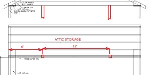
That would work, however your time/materials and labour would be lot less to just do the ridge...and just cut 100% of the ties out. You'd also need an engineer to run the numbers on the stressed skin solution you're proposing as you would likely need some sort of beam (on edge) to cap the cut ties and support the 24 ft of unsupported truss ties projecting 4' into the space. That structure would likely need to be skinned on both sides of the cut ties as well with PL adhesive etc. So a lot of time and $$$ vs the ridge beam and cross supports.

You could achieve the same by doing 16" x 3 LVL on edge, (on both sides of the garage) to reinforce the walls, but you'd need to tie those at both ends. Still less material/cheaper to do the ridge.

Six x 18" LVL at 24" feet long and you're done for about $1300 in materials to do a ridge and cross support beams. If going full length, the rear LVL cross support could be omitted and replaced with a 2x6 (x3) post, so you're only needing four x 18" LVL at 24'.
 
To avoid these ads, REGISTER NOW!

billconner

Well-known member
Joined
Jul 20, 2021
Messages
6,963
Location
Thousand Islands NYS
Yes that would work same as the beam I proposed. But just like the beam, it increases the forces at the ends of the plywood, so more rafter ties or other tension member.
 
OP
M

MikeC55

Well-known member
Joined
Nov 1, 2020
Messages
420
Location
CT
Hi Denwood, I'm trying to decipher page 8 of (your 2nd link). I see the live load 30/ dead load 15, if I do a 12' raised section, beam support spacing is 12', width of building segment is 24', the beam breadth x beam depth shows 3.5 x 9.5 and 1.5/3. The LVLs are 1.75" thick, so that would be 2 of them. I don't understand where the 3 x 16" you mentioned comes from. If I were going to add a ridge support the full length of the garage (24'), the table says 5.25 x 16 or 3 x 1.75 x 16". I think this is where you got the 3 x 16". The 1.5/3 refers to the bearing area dimension needed at beam support but I'm not quite sure how to interpret it.

Is there a way to estimate the rafter tie support beam requirement from these tables? (which is more like a point load at center span?)
 

billconner

Well-known member
Joined
Jul 20, 2021
Messages
6,963
Location
Thousand Islands NYS
Is there a way to estimate the rafter tie support beam requirement from these tables? (which is more like a point load at center span?)
I started to do just that. To get close, a beam that supports a 1000 pound point load at center will support 2000 pounds uniform. So each end of 12' ridge beam is 3240#, thus the tie beam should be selected to support 6480 uniformly or 270 plf. Of course have lumber yard do final calcs. Structures 101 in grad school.
 

Denwood

Well-known member
Joined
Sep 22, 2014
Messages
4,186
Location
Thunder Bay, Ontario, Canada
My cross beams are indeed the same spec as the ridge, and yes, it's a point load at center in this case, versus the distributed load across the ridge. Just find a truss shop locally, and they almost certainly can run these numbers for you if you purchase the LVLs from them. I figured the ridge for your application could be 2 x 18" or 3 x 16" based on a 24' span, and 24' wide building on page 8. You're correct on the width vs beam count. You likely don't need a rear cross beam if you use a post..and you'd be quite safe in using the same 2 x 18" (or 3 x 16") for your front door header/ridge support. I think you'll find the 2 x 18" a fair bit more cost effective.
 

Innovate1

Well-known member
Joined
Jul 28, 2014
Messages
4,288
Location
Illinois near St. Louis, Missouri
I started to do just that. To get close, a beam that supports a 1000 pound point load at center will support 2000 pounds uniform. So each end of 12' ridge beam is 3240#, thus the tie beam should be selected to support 6480 uniformly or 270 plf. Of course have lumber yard do final calcs. Structures 101 in grad school.
Hardly grad school stuff. More like first or second year undergrad. For lumber western wood products association puts out a free spreadsheet to do this stuff but it doesn't do LVLs.
 
OP
M

MikeC55

Well-known member
Joined
Nov 1, 2020
Messages
420
Location
CT
I hate to admit it but I did take Statics as part of my ME degree back in the late 70s but I haven't been able to find my old book (it's here somewhere). I see there are some open source texts on-line that I plan to peruse while on vacation for a few days. I do remember the sum of force vectors and sum of moments stuff = 0 (unless you want motion !), sigma = Mc/I, free body diagrams, etc. I'm going to draw up what I'm thinking and see what a local truss company can offer. I'd like to understand the design process but would still want someone who does this stuff every day to do a sanity check. Bridges have fallen down but for a factor of pi....
 
OP
M

MikeC55

Well-known member
Joined
Nov 1, 2020
Messages
420
Location
CT
Doing some simple calculations for the raised roof section (12 feet of the total ridge length of 24'), I get total load on the raised area of 24' x 12' = 288 sq ft; loading 50 psf, gives total roof load of 14,400 lb in the raised area. Half of that would rest on each of the two cross tie beams, 7,200 lbs over a 24' span is 300 plf (pretty close to Innovate's number). Looking at the Versalam chart, which only specifies 'US East Snow Load Tables' (I can't find where they mention assumed live load of snow) and does not indicate how the beam is being loaded https://bmc.a.bigcontent.io/v1/static/Boise_Cascade_Versa-Lam_LVL_Eastern_Design_Guide_2020/.pdf the 24' span, says I need to use 3 x 14" (1 3/4" thick) LVL to support 333 plf. Does that sound right? It seems like an awful lot of beam.
 

firebirdparts

Well-known member
Joined
Jun 8, 2016
Messages
10,607
Location
Kingsport, TN
1657128654342.png

I raised the ceiling for a portion of my garage this way.

1657128769923.png

couple of built up beams from lumber, and one honker of a LVL beam, just throwing additional ideas in for you
Glad to see you and Bill discussingthis. We don't get much discussion on this method, and evaluating it is something you wouldn't see in any span tables.
 
OP
M

MikeC55

Well-known member
Joined
Nov 1, 2020
Messages
420
Location
CT
I do kind of like the scissor truss mod this guy does to his garage.
It appears that original trusses are 2 x 4 and I'm not quite sure what he is doing with the new 2 x 4 he adds to the rafter area but it would seem you could do this same sort of modification to rafter construction where you would add each piece for the scissor on opposite sides of each rafter and then have the vertical tie sandwiched in the gap between the scissor boards. 2 x 4s could be plywood gusseted in if needed. It would be nice not having to worry about lifting / maneuvering any real heavy beams.
 

billconner

Well-known member
Joined
Jul 20, 2021
Messages
6,963
Location
Thousand Islands NYS
Here is a sketch of a horizontal beam at top plate to resist rafter thrust, around 500 plf. I used a 11.75 LVL but there are other choices.

FYI the thrust calculator is here: http://www.timbertoolbox.com/Calcs/raisedtiethrust.htm And my values in that:

This allows a 12' section of garage fully open to rafters, which was the challenge I believe. In my mind this is simple, safe, and a few hundred dollars versus a few thousand to change to a structural ridge and support it, possibly having to add foundation.
 

Attachments

  • rafter thrust.JPG
    rafter thrust.JPG
    110.2 KB · Views: 30
  • GJ RAISE TIES Model (1).pdf
    10.9 KB · Views: 14
Last edited:
OP
M

MikeC55

Well-known member
Joined
Nov 1, 2020
Messages
420
Location
CT
Wow, that is interesting for sure Bill. Do I understand the gussets correctly? The plywood goes the full length of the LVL and ties the wall top plate to the LVL? The 2 x 6 gussets apply at each rafter? (would you nail them through the LVL on bottom?) Also, is the triple tie beam a 2 x 8 or 2 x 10? In addition to being fairly inexpensive, it's all done at the 8' level although I still have to get up to the ridge board and install rafter brackets. For the 672 lb load number, did you use 50 psf or something lower? I come up with 767 lb @ 50 psf.

One more thing, when looking up the LVL beam, Since you've already factored in the snow loading in the 500 plf, when you go to the beam tables are you just going to the 'no snow load' table for 12' span? It seems that way if I'm understanding the table.
 

Attachments

  • Horiz Beam.jpg
    Horiz Beam.jpg
    112.8 KB · Views: 25
Last edited:

Denwood

Well-known member
Joined
Sep 22, 2014
Messages
4,186
Location
Thunder Bay, Ontario, Canada
The horizontal design works too...but if you want to go 24" the beam spec is a lot different. I figure the LVLs to do the ridge would cost about $1000 if you support the rear with a post. I suspect your time vs materials will be quite similar for a ridge vs horizontal beam, particularly if you're only going 12 ft. The horizontal beam would give you ~14" of extra clearance at the peak...perhaps a non issue if you account for roof slope vs car width/contact points. On the 12 ft issue, you should go a minimum of 16' with your opening as even at that length you will have potential issues with hood or rear windshield contact with SUVs on a lift. I would go 20', or 24' if I had the option. If you're only using a small lift (48" ... won't matter as much if you place the lift posts carefully) but if you're lifting anything more than 4 feet, I'd strongly recommend a roof "window" of 20 feet so hood or rear glass contact is not an issue.

The gussets on the horizontal beam would go between the rafters, over your top plate and along the full length of the LVL...so you'll have pieces, tied as well into the 2x6 rafter gussets. You'd need to follow the fastener schedule provided by the engineers. You have critical connections at the triple rafter ties as well. I do like the horizontal beam design and have wondered why it's not used more for these applications...although for my application the ridge works well as I dropped my vertical storage down to 7ft (on an 8 ft wall) which makes a huge difference for storage up there with nothing projecting from the walls.

The ridge will have fewer framing details/gusset/tie in details...where as the horizontal beam will allow you to work at 8ft. I suspect price will be a wash once you purchase plywood etc.

An engineer who could sort the details on dropping a horizontal beam design down the wall a bit, and using a larger LVL would give you a pretty nice surface for extra storage. I'm always looking for room to keep 16" lengths of material under cover.
 
Last edited:
OP
M

MikeC55

Well-known member
Joined
Nov 1, 2020
Messages
420
Location
CT
Thinking about those triple tie beams, I figure something like tensile force in each triple beam at around 3,800 lbs. Cross section of 2 x 8 triple beam is 33.75 sq in, giving tensile stress of about 113 psi. I see allowable tables for common lumber but they only give compressive and bending stress. If I assume the max bending stress in the beam is only due to its own weight, I come up with 272 psi, which I think is ok.
 

billconner

Well-known member
Joined
Jul 20, 2021
Messages
6,963
Location
Thousand Islands NYS
Sorry for delay, in a building code committee meeting all afternoon. I thought plywood gussets between the rafters and 2x6 stubs - which are just to support the lvl from turning. Might do that with a vertical from rafter. Figured plywood was glued and stapled to hold till glue set.

I didn't study the joists to much but thought I showed more than existing number of ties. I initially suggested a steel angle tie - one leg vertical to one tie for supporting the angle and one horizontal for anchoring to the lbs. As to tie size - if no storage load, same as now. Worked before - 60 years I think you said - so good. You or someone suggested storage lofts at the ends - and I wondered what would span 24'. I think making ends storage will be expensive. I feel like I'm alone here in trying to save money, rather than spending your money.

For load I used 45 (15DL+30LL) which came to 672 per joist (1'-4" x11'-6') and divided by 1.33 FC or old. Then I just looked in floor load table 12' spans and total >500 plf total.

Does this help? Remember - I thought of this when I understood you wanted 12' clear, and musings of only 8'. It's not a practical 24' solution imho. And it an option, a very economical one, for what I understood you wanted to do. Nothing wrong with structural ridge but I saw it as triple 18s at ridge and at garage door header, a post at rear of and new foundation under three new point loads. ( I'm never optimistic about 60 year old garage foundations - look at thread on the busted out blocks - no pins, no fill, probably no footings.)

ps: timberlocks through lvl into rafter ties. maybe obvious.
 

Innovate1

Well-known member
Joined
Jul 28, 2014
Messages
4,288
Location
Illinois near St. Louis, Missouri
Doing some simple calculations for the raised roof section (12 feet of the total ridge length of 24'), I get total load on the raised area of 24' x 12' = 288 sq ft; loading 50 psf, gives total roof load of 14,400 lb in the raised area. Half of that would rest on each of the two cross tie beams, 7,200 lbs over a 24' span is 300 plf (pretty close to Innovate's number). Looking at the Versalam chart, which only specifies 'US East Snow Load Tables' (I can't find where they mention assumed live load of snow) and does not indicate how the beam is being loaded https://bmc.a.bigcontent.io/v1/static/Boise_Cascade_Versa-Lam_LVL_Eastern_Design_Guide_2020/.pdf the 24' span, says I need to use 3 x 14" (1 3/4" thick) LVL to support 333 plf. Does that sound right? It seems like an awful lot of beam.
I think those were Bills numbers not mine... It sounds like you are calculating the cross beams that support the ridge beam in the center. In that case it's a point load not a distributed load so by figuring as a distributed load you are under designing. But you also seem to be over on the ends of the beam. The ridge beam supports half the total load (the other half is supported by the walls. So total ridge beam supports 7200 lbs total with 3600 lbs on each end. Then again, I may not be following what you were calculating....
 

Innovate1

Well-known member
Joined
Jul 28, 2014
Messages
4,288
Location
Illinois near St. Louis, Missouri
It appears to me that the outward force at the walls is the same as the ridge beam load (from the calculator that was posted). In that case the load is distributed along the beam so a smaller beam could be used. And your number of 3800 lbs tension at each end sounds about right (I got 3600 lbs which is half of 7200 lbs). Great discussion. Glad to see this go beyond guesses of what seems good to actual calculations of loads.
 
OP
M

MikeC55

Well-known member
Joined
Nov 1, 2020
Messages
420
Location
CT
Thank you for the feedback Bill and Innovate1. I see where I did make a mistake on the ridge beam / cross tie scenario where the point load on each cross tie is 3,600 and not 7,200 (the walls taking half the load). Over the 24' cross tie span that's 150 plf (assuming distributed load). This could be satisfied with a 2 ply 11 7/8" LVL which seems much more reasonable.

On the horizontal beam idea, I think I understand the basics now. If I want to use the ends for storage, I think I'd have to consider a post mid-span. Seems like a fair trade-off.

I still need to add some framing for insulation. Since I have no collar ties, I could combine this function with holding insulation and lightweight metal ceiling panel. 2 x 6, since I'm not counting on them structurally?
 
Last edited:

Innovate1

Well-known member
Joined
Jul 28, 2014
Messages
4,288
Location
Illinois near St. Louis, Missouri
Thank you for the feedback Bill and Innovate1. I see where I did make a mistake on the ridge beam / cross tie scenario where the point load on each cross tie is 3,600 and not 7,200 (the walls taking half the load). Over the 24' cross tie span that's 150 plf (assuming distributed load). This could be satisfied with a 2 ply 11 7/8" LVL which seems much more reasonable.

On the horizontal beam idea, I think I understand the basics now. If I want to use the ends for storage, I think I'd have to consider a post mid-span. Seems like a fair trade-off.

I still need to add some framing for insulation. Since I have no collar ties, I could combine this function with holding insulation and lightweight metal ceiling panel. 2 x 6, since I'm not counting on them structurally?
For the cross ties (joists at top of walls) that hold up the ridge beam you can't figure that as distributed load. It's a single load in the center (the ceiling load is distributed but that's a lot less weight). From what Bill posted this about halves the load that a beam can carry. A beam that can carry the ridge beam and span 24' is going to be pretty big. Might want to compare to the beams that Denwood used - I don't recall how close his dimensions are to yours.

For your last point I think you are saying you still want to make a flat section of ceiling in the middle. They are structural only from the point of holding up the ceiling. That's a fairly small load added to the rafters that will make the rafters a bit undersized although it may not be enough to be an issue.
 
Last edited:

billconner

Well-known member
Joined
Jul 20, 2021
Messages
6,963
Location
Thousand Islands NYS
Mike - I'm no longer sure of your requirements. The attic storage complicates things. TJIs would work for attic and for rafter ties but loosing height in storage area and not inexpensive. Not sure where mentioned columns would go.

It took me 6 months of drawing - probably more than a half dozen truely different schemes - to get to my 28 x 32 in the $15-18k range. I think it's that "the devil is in the details" thing for me, trying to visualize every joint and connection.

Please ask if anything I suggested needs clarification.
 
To avoid these ads, REGISTER NOW!
OP
M

MikeC55

Well-known member
Joined
Nov 1, 2020
Messages
420
Location
CT
Hi Bill, the areas at ends of garage where ceiling is still flat would be for storage. I think adding columns as shown would allow me to use these areas for moderate storage (the single rafter ties are 2 x 8). What are TJIs ?
 

Attachments

  • Attic.jpg
    Attic.jpg
    92.4 KB · Views: 17

Innovate1

Well-known member
Joined
Jul 28, 2014
Messages
4,288
Location
Illinois near St. Louis, Missouri
Hi Bill, the areas at ends of garage where ceiling is still flat would be for storage. I think adding columns as shown would allow me to use these areas for moderate storage (the single rafter ties are 2 x 8). What are TJIs ?
You would need to add posts for all the joists in the area used for storage. If walls wouldn't interfere with use of the space you could build some short walls in that area.
 

billconner

Well-known member
Joined
Jul 20, 2021
Messages
6,963
Location
Thousand Islands NYS
Yes. I didn't realize you were ok giving up the 2 car option.

A couple of short beams (<6' I think) from columns to rear wall - maybe a couple of 2x4 studs under - and to 'new jack studs supporting new garage door header' (??) would provide all the necessary support to or storage loads.

You probably will need a footing and pier under columns.

I have to ask if the attic storage is worth it. Up here you can get an Amish built 200 sq ft shed delivered for ~$3000-3500. A lot more convenient storage, especially if it eliminates the columns and replacing garage door. The 2 LVL beams are under $350 together and the rest is relocating the existing ties, maybe a few supplemental ties.

Just a thought. I am one of those people who is often being told to spend money on myself, influenced by parents married early in "the great depression" and struggled.
 

Denwood

Well-known member
Joined
Sep 22, 2014
Messages
4,186
Location
Thunder Bay, Ontario, Canada
Your cross ties (in a ridge scenario) should have no issues with some storage as you can always over spec them. If you're only talking 4' on both ends, you can use the cross tie as support and sister a few truss ties. My storage area is topped with 3/4" ply to effect the loft at both ends of the shop. It was only 4' and the ply sits on the wall side on 2x4 strapping to support that edge, so the remaining 3 truss ties (at both ends) aren't doing much for support.

On the ridge, if the beam is spec'd for total live/dead load of the roof, then you're at a .5 safety factor as ya, 50% of the load is on the walls. Pretty sure that is what happened with my ridge beam LVL spec...just 2 x 12" LVLs for a higher snow load than you. The shop however is only 16' wide, whereas yours is 23'. But again, I'd have the guy selling you the LVLs run the numbers for their specific LVL as they all differ in specs regardless of doing a ridge or horizontal beam.
 
OP
M

MikeC55

Well-known member
Joined
Nov 1, 2020
Messages
420
Location
CT
Yea, I really want it to be a workshop and not a 2 car garage (I will eventually add onto the house and have a 2 car garage there). So this detached garage will get a 12’ door in place of the 2 9’ doors it has now. That is a very good price for the shed Bill. I don’t know if I could build a 200 sq ft shed myself for that…
 

billconner

Well-known member
Joined
Jul 20, 2021
Messages
6,963
Location
Thousand Islands NYS
Well, based on that, another variation. Consider running beams front to back 12' apart - the new columns that I visualize on a 12' x 12' - and gaining side lofts as well. And instead of the horizontal LVL, use plywood - as was suggested by another earlier - as a big gusset. Put in the columns (6x6s? or maybe 4x4s), two beams (double 8x8s or 2x10s maybe?), header off the middle rafter ties, and plywood floor the "attic" with screws and glue. I don't quite how how to calculate the strength of the plywood diaphragm, but I'm sure its strong enough. More loft storage and lower cost - and all work (except insulation and ceiling) at an easy working height. Plywood joints need to be thought about - I don't think a seam splitting a two-by is quite strong enough. A double layer of ply would do it. I might experiment double 3/8 on edges and 3/4 at ends. Two 6' x 16' areas of double 3/8, and rest 3/4. Find a good glue roller for the ply or use contact cement.

The plywood on the sides shouldn't be much more than the LVLs, you can use up the cut out rafter ties to supplement at edges, and I think it all will look better. Now, can you use the lift like an elevator to move things to attic storage?
 
OP
M

MikeC55

Well-known member
Joined
Nov 1, 2020
Messages
420
Location
CT
That is a fascinating idea Bill. I'll draw it up. I was hoping to do the garage door and associated header changes last though. I think this would force me to do it first since those front to back beams would rest close to the limits of the new (12') garage door. But I do like the plywood diaphragm doing double duty as storage floor and bracing for horizontal thrust.
 

billconner

Well-known member
Joined
Jul 20, 2021
Messages
6,963
Location
Thousand Islands NYS
If I were drawing it, I think the side storage decks should cantilever over the column lines and beams 6" or so for appearance. Maybe columns shift out or clear width of opening is a little under 12'. I just think that square opening within the square room has a nice dynamic. Like it should have a loop of LED tape light on it's fascia.
 
OP
M

MikeC55

Well-known member
Joined
Nov 1, 2020
Messages
420
Location
CT
Here's a quick sketch but it seemed to me if I were going this way, I'd go the full 24'. I like the cantilever idea but didn't sketch it that way here. The one thing I'm not sure about is unlike the horizontal beam where it is secured under the existing ties and top surface of it is even with top of wall (to nail/glue the plywood gussets), here, the plywood would be on top of the interrupted rafter ties. I guess if you beefed up the rafter tie connection to the wall with metal brackets and reinforcement gussets and the plywood take the horizontal thrust from there? The other thought I had if going this way was that a beam could be run under the rafters at the same distance from side wall as the columns and extend the columns up to that beam. It would only have a maximum 12' span between the columns and take more of roof load down to foundation. Doing footing under the column bases could easily be added to the slab pour for the car lift pad too (it just moves it up to do first, before garage mods). Just thinking out loud...
 

Attachments

  • GR2-1.jpg
    GR2-1.jpg
    51.8 KB · Views: 22
  • GR2-2.jpg
    GR2-2.jpg
    61.6 KB · Views: 16
  • GR2-4.jpg
    GR2-4.jpg
    48.4 KB · Views: 14
  • GR2-5.jpg
    GR2-5.jpg
    44 KB · Views: 20

billconner

Well-known member
Joined
Jul 20, 2021
Messages
6,963
Location
Thousand Islands NYS
Regarding connection to top plate, I did think about exactly what you bring up. In the end, I felt a good connection of partial rafter ties to top plate was adequate. I would.run a timberlock through top plate into each rafter and rafter tie, and some 16 penny nails between the two. I have read the timberlock is as good as the Simpson Strongtie connectors.

I was very comfortable with the 12' span between rafter ties. Felt it easily met the when in doubt build it stout mantra. At 24', I think it's about 4 times the bending moment on the plywood diaphragm. The rafter thrust will try to bend the diaphragm which would try to make the inner edge buckle upward. I might look at a vertical (2x4) every other rafter to diaphragm. Of course stuff stored there will counteract the buckling too, and a 2x8 at edge is likely sufficient.

I was 100% sure the 12' horizontal beam/diaphragm spans were fine, especially with the 6x24 decks at either end. I can't be quite as sure at 24' with no decks stiffening it. 16'? Lots of good tall storage lost also.

Certainly if replacing/modifying slab the column footings are easy.
 
OP
M

MikeC55

Well-known member
Joined
Nov 1, 2020
Messages
420
Location
CT
Here I modified it to about 14.5' open area. I'm using triple 2 x 8s on the 14.5' span. Maybe should LVL there.
 

Attachments

  • GR3-1.jpg
    GR3-1.jpg
    61.9 KB · Views: 20
  • GR3-2.jpg
    GR3-2.jpg
    43.3 KB · Views: 18
  • GR3-4.jpg
    GR3-4.jpg
    42.8 KB · Views: 22

billconner

Well-known member
Joined
Jul 20, 2021
Messages
6,963
Location
Thousand Islands NYS
I think trip 2x8 it should be fine - it does a lot more work between column and gable walls which is why I thought it would be 24' long under rafter ties. Not sure if the end 24' rafter ties spanning 24' will support the storage loads.

I'm not sure what is rising vertically above the deck. You shouldn't need anything. The "donut" deck being stiff should be all that's needed. And collar ties are rarely needed. At best the keep rafter pairs tied together, which can be better done with metal straps. Plus they make it hard to air seal ceiling membrane (which I presume is at rafters.)
 
OP
M

MikeC55

Well-known member
Joined
Nov 1, 2020
Messages
420
Location
CT
Still wrestling with the way to go on this. I prefer the ridge beam for the straight forward, simple design but at 10 Lbs per linear foot, a 1 3/4 x 11 7/8 x 16' beam is 160 Lbs. I'm not sure I want to try and wrestle that up to the ridge. I have a block & tackle that would help once I get it on top of the existing rafter ties. I could install an eye hook into the existing ridge board (a 2 x 8) and then use B & T to lift it up near the peak. Maybe add a collar tie near the peak on each end to temporarily hold it until I can get a support under it to the cross tie? Any ideas besides brute (human) force?
 
OP
M

MikeC55

Well-known member
Joined
Nov 1, 2020
Messages
420
Location
CT
It looks like I was in error on the bean weight. At 5.9 Lbs/ft, a 16 .5', 1.75" x 11.875" LVL should weigh in around 100 Lbs. That seems more do-able for 2 guys. Based on a 16' long span on ridge beam and loading of 50 plf, I come up with 9,400 Lbs supported by the ridge and 4,700 Lbs at each end support for it. The loading on the ridge is 9,400 / 16' = 588 plf. It looks like a 2 Ply of the above beam should suffice. I would welcome anyone to check my conclusion here.

On the cross tie support beams for the ridge, I still plan on using columns spaced 12' apart so max unsupported span is 12'. What I'd like to do if it's acceptable is use a single ply spanning the full 24' (LVL 1.75" x 11.875") but then screwing/bolting a 12' LVL of same spec to each side of the 12' span. Assuming a point load of 5,000 Lbs at the center, I get max bending moment of 15,000 Lb-ft and max bending stress of 1,459 psi. The tensile load in the beam is 10,179 Lbs (using the raised rafter tie calculator with H = h) and stress in the single ply portion comes out to 245 psi, which seems acceptable. I'm not sure if this tensile stress is added to the bending stress but assuming it is, that seems to be an acceptable number (1,704 psi). Do these numbers seem reasonable?

The blue lines are rafters, black lines, existing rafter ties and red, the ridge beam and cross tie beams.
 

Attachments

  • Ridge top.jpg
    Ridge top.jpg
    106.1 KB · Views: 16
  • Beam loading.jpg
    Beam loading.jpg
    59.8 KB · Views: 14

billconner

Well-known member
Joined
Jul 20, 2021
Messages
6,963
Location
Thousand Islands NYS
Not the lvl structural ridge proponent but I looked at the Versa Lam lvl roof load tables, 115% duration. I concur with ridge but see a single 14 should work.

I didn't check the cross beams and tension.

I suggest a diagram with loads and dimensions and have lumber yard calculate.

Are you leaving the existing ridge board and rafters at ends? I would consider running ridge beam to ends. I know it complicates install but worry about the joints.

Not convinced the non-engineered sistering with 2x10s and raising all rafter ties isn't simpler and less expensive.
 
To avoid these ads, REGISTER NOW!
Top Bottom