Badass job on the tractor, I’d love to have one like it
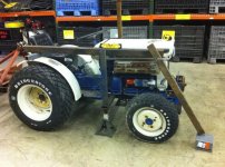
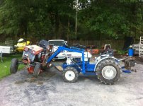
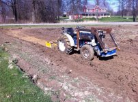
traded an old roller fox body for it that was rotted out. guy bought his uncles mini farm and it was parked years before where it had run out of fuel. showed up, bled the fuel lines and jumped it. buddy was HOT when I drove it onto the trailer. they tried for days to get it running. 4x4 and 2 cyl diesel. the thing literally sipped fuel. It was literally the size of a garden tractor, but could do real tractor work. I was in in very cheap right after I bought my house and used it to re-grade the wetland that used to drain towards the house. actually built the loader to do that, but ended up finishing the loader the winter after fixing the yard.
IT was stout little tractor, but the fine spine Reversed Pto was hard to find backwards implements. no matter how hard I tried with double nutting or locktiting things, the blades on the mowers and brush hogs always came off. it was a great tractor for the time, but sucked to mow with. sold it for 4500 as a quick sale to buy a Kubota BX that was more lawn mower with a little loader and a hydraulic front dozer blade with a "hurt" motor. I had a smaller kubota lawn mower and had dealt with alot of kubota smaller motors with our gen sets at work so I took the chance.
still running that "hurt" motor to this day. is amazing what an electric lift pump will do. the thing ran, but barely. was getting a lean knock and only hitting on two cylinders.
I miss the lifting capacity of the one I built, but this is a better lawn mower that can do a few other things. I sold the kubota lawn mower last summer after keeping it around for years incase the BX needed a motor.
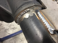
while we are on the tractors and not to derail from the thread, heres a few other welding projects.
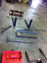
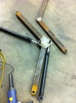
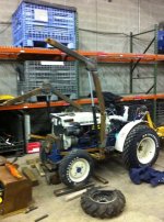
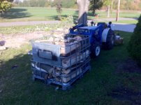
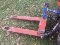
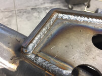
made a set of 3 point forks out of an old pallet jack from the scrapyard. I use this to move crates of firewood around with the new tractor since the loader won't pick up more than 1K lbs. i gutted the tie bars and cylinder off of it. added a piece of 3" I beam on the inside where the pin mounts are. added some 3/8 angle for the pin mounts and some box tubing on the top for the top link. worked well until I got a free set of forks from a scrap forklift and made another that was adjustable. that can be seen in the snow pic. oh that roofline is 10' tall if that give you an idea of how much snow is there lol.
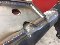
I also built a real weight ballast that can hang suitcase weights and also doubles as a trailer mover. this takes up way less room when moving engines and heavy things inside the shop than a box blade hanging off the back.
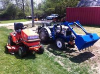
if you look close, on the little kubota garden tractor, you can see the front hitch i made. I made a snow plow setup for it and used the receiver setup as the Quick disconnect. I tied the lift for the snow plow into the mower lift deck with a three way valve since it was a fairly low pressure running off HST pressure. the Hyd line is wrapped up around the hitch in front in the picture with both tractors. you can also see the front weight box on the Satoh (also on a reese type front hitch). the beaver was so little, it needed 150-200lbs on the nose when running a brushog or box blade. also can be seen in one of the grading pics. it had a front PTO and I had to be created to get the hitch in the front without interfering with the pto setup.
I guess you can say I like my receiver setups.


")


