I received the document for the dust bag to cartridge filter conversion but forgot to post it here. Time for me to get to work on this.
VISTA INDUSTRIAL EQUIPMENT
TECHNOLOGY & SUPPLY LLC
e-mail:
[email protected]
website:
www.VistaIndustrial-LLC.com
11943 Front Street Voice: 562.426.2107
Norwalk, CA 90650-2900 FAX: 562.426.9848
Specializing in MRO of Grit Blast Rooms & Systems
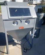
CONVERTING A CYCLO*BLAST GLOVEBOX BLASTER
FROM DUST BAGS TO FILTER CARTRIDGE(S)
Items required:
>3/16” steel plate, as described below
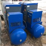
>an air reservoir (tank) no smaller than 10” diameter x 30” long
>(2) diaphragm pulse valves (McMaster-Carr 5496T11)
>(2) Humphrey TAC 3P pushbutton actuators
>(2) 3/8” x 36” all-thread
>(2) 12” lengths of ¼” steel round bar
>3/4” hose, pipe & fittings to connect the air reservoir to the pulse valves
>(2) 19215-C Filter Cartridges
First, remove all dust bags from the dust bag frame and thoroughly clean the inside of the baghouse enclosure. Welding may be required, and abrasive dust is explosive.
Remove the bag-rapping mechanism and seal all holes in the enclosure. Set the dust tray aside for later use.
Measure & cut the 3/16” steel plate to fit the angle-iron dust bag frame. Cut (2) 6” diameter holes in the plate, equally spaced to accommodate the filter cartridges, then secure the steel plate into the angle-iron frame. This plate is called the tubesheet, and the cartridges will seal up against it.
Standard dust collector filter cartridges are 12-3/4” OD x 8-1/4” ID x 26” L, with an open top & small hole at the bottom for the J-bolt. Once installed, (2) cartridges will ventilate this glovebox much better than the (40) dust bags currently in it.
The air reservoir can be anything handy, a scuba tank, welding gas cylinder, etc. It will already have an inlet (usually on one end), but what it now requires are (2) outlets. These can be made by sawing a ¾” x 6” pipe ****** in half. Each half should then be welded to the side of the reservoir. But wait to do this until after you hang the cartridges.
The (2) 12” lengths of ¼” steel round bar should be tacked across the middle of the 6” holes in the tubesheet. After securing them, use a small sledge & chisel to tap downward in the exact middle of the bar, creating a “notch” that will center the J-bolt when it is tightened.
The (2) 3/8” x 36” all threads should be bent into a “J” on one end, tightly enough to fit snugly over & into the “notch” on the ¼” round bar. You now have hangers for the cartridges, so hang them up. Getting the end of the J-bolt into the hole at the bottom of
the cartridge is not easy, but keep at it until the cartridges are secure against the tubesheet.
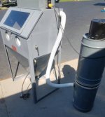
To provide air to the reservoir, install a tee in front of the ball valve on the piping manifold of the machine. Connect an air hose (minimum ½”) from this tee to the inlet on the reservoir. Make sure you are upstream of the on-off ball valve so that the reservoir will stay pressurized even when not sandblasting.
Now it’s time to position the air reservoir and install the (2) outlets. It appears from the pictures that the reservoir can be positioned laterally on top of the glovebox section, with the inlet on the LH facing end for connection to the air line from the tee. Now you weld the (2) 3” half-******* to the reservoir, taking care that there is clearance for the reservoir itself, as well as the incoming air hose and the (2) outgoing air hoses.
The pulse valves should be installed on the top of the back wall of the former baghouse. There will be air hoses from the reservoir to the pulse valves, and ¾” piping from the pulse valves to the cartridges. The pulse valves have directional arrows; make sure the air from the reservoir is piped according to these arrows!
Measure the distance from the pulse valves to the center of the cartridges. ¾” piping will extend inward from the pulse valves and should stop near the center of each cartridge. To the end of each pipe, attach a ¾” 90-degree elbow and a ¾” x 3/8” hex reducer, pointing downward into the cartridge. Insert a 3/8” x 6” ****** into the hex reducer.
Once the pulse valves, hoses & piping have been installed, screw the pushbutton actuators into the 1/8” ports on the pulse valves.
When testing the system for the first time, sloooowly open the air line to the reservoir. Check for air leaks. Other than the sound of the air pressuring the reservoir, there should be no leaks.
With the reservoir pressurized, push one of the actuators. There should a loud bang as the pulse valve releases the contents of the reservoir into the cartridge.
Congratulations! You now have a reverse-pulse filter cartridge cleaning system.
For actual use, at the end of each blasting session, turn off the electrical and let the blower motor spin downà this can take a full minute on some motors. Once the motor is off & still, push the actuators 3-4 times each, waiting until the reservoir refills between each push.
Do this & walk away. The next time the machine is used, before you turn on the air, before you turn on the electrical, EMPTY THE DUST TRAY!! If you don’t, as soon as you turn on the blower motor, air will enter the enclosure, pick up the dust on the tray & put it right back onto the cartridges. This called re-depositing, and it completely nullifies what you did to get the dust out of the cartridges. So pulse those valves good….and get rid of the dust the next day.