To avoid these ads, REGISTER NOW!

The Everything 3D Printer Thread

Gerald O

Well-known member
Joined
Mar 5, 2013
Messages
1,884
Location
NC
To avoid these ads, REGISTER NOW!

Outlander

Well-known member
Joined
Jul 30, 2010
Messages
5,154
Location
Quebec, Canada
So now I've done it, I can officially join this thread and suffer the indignity of failed first print and thrill of victory for the successful second print!

After chatting with some engineers at work I decided on the Creality Ender 3 PRO, and I exploited Mrs Outlander's generosity with her Amazon Prime account. "Don't know why you need a 3D printer, but men need hobbies" :rocker:

So I won't bore you with unboxing and build details. I did decide to repupose a Raspberry Pi 3B that I had for testing and I installed Octoprint and set that up.

Then, the "agony of defeat"...what is that even supposed to be?:wtf:
View media item 106424
Then the internet came to the rescue. I re-leveled the bed using paper process, modified all the settings in Cura as per "best practices" and voila, the "thrill of victory"!
View media item 106423
Mrs Outlander finds it ironic that my first print on my new printer is a set of clips for the ribbon cable of my new printer.

I have lots of ideas for more prints, mostly for electronics and garage related stuff. So, I'm assuming I'll get addicted quickly to the end-to-end process of identifying a need, designing the solution, modelling, slicing and production. Just like work, only fun :evil:

Going back now to read the thread from the beginning!!!!!
 

white91formula

Well-known member
Joined
Dec 11, 2012
Messages
424
Location
Boston, MA
Made these up over the past few days. Still need to make one for my long torx.

I was sick of all of my hex bits and torx bits floating around in my toolbox
 

Attachments

  • 20200911_182128.jpg
    20200911_182128.jpg
    111.6 KB · Views: 227
  • 20200909_200442.jpg
    20200909_200442.jpg
    153 KB · Views: 202

Outlander

Well-known member
Joined
Jul 30, 2010
Messages
5,154
Location
Quebec, Canada
Nice, white91formula. I like the idea of my prints being useful. After my brief success with the ribbon cable clips I moved onto a frame for my arduino test bed.

View media item 106574
View media item 106575
The first (pictured above) was done with Cura and I made a second one using the Prusa slicer with similar settings. Results were similar, but not quite the same. Interesting.

Once I'm convinced I'm doing it right I'll learn to tweak settings and be more adventurous with bigger prints!
 

niget2002

Well-known member
Joined
Oct 2, 2012
Messages
11,112
Location
Josephine, TX
I made a full enclosure for a mixer/doser for aquarium ferts. 993dc413da720f6d2b866303cbb9fcae.jpg

Sent from my LM-G820 using Tapatalk
 

Attachments

  • 993dc413da720f6d2b866303cbb9fcae.jpg
    993dc413da720f6d2b866303cbb9fcae.jpg
    165.2 KB · Views: 24

wrenchguy

Well-known member
Joined
Sep 22, 2011
Messages
4,697
Location
NW Indiana
Can this be reproduced and how can i find someone reputable to do the job? Hopefully local? Original pieces are available as samples.


er15

New member
Joined
Nov 20, 2016
Messages
4
Location
Colorado
I made some sub-divider bins for my Durham drawers so my small stuff doesn't take up whole bins. Also handy if you need to take the bin with you to a different location without lugging the entire drawer. I've really been liking them for keeping things organized and getting the most out of my Durham drawers.

Files are published if you want to make your own - github.com/ericrlau/DurhamBins
 

Attachments

  • DurhamInside.jpg
    DurhamInside.jpg
    152.5 KB · Views: 163
OP
B

BoilermakerFan

Well-known member
Joined
Apr 17, 2006
Messages
2,188
Location
Indianapolis, Indiana
I've been off GJ for a few months. Mostly because I've been busy doing home improvement projects, WFH, and my son is doing his freshman year of HS virtually until the pandemic settles down or a viable vaccine is released.

I updated my Killing Time thread and still have a few more updates to post over there.

I finally received my Biqu parts but never installed any of them yet. I still need to print a new PSU mount for a Meanwell 24V supply. Haven't installed the ring heater yet either. I'm not touching my printer until I have all the parts I need for the rest of the upgrades finished.

I haven't run the printer since mid-August. It's a lot quieter than it was, but it's still a Mk2.5S so it's definitely not silent. It distracts my son when he's doing is school work and I can't run it at night until I build the soundproofing enclosure.

But I'm glad to see you guys are keeping this thread alive.


Atomic had good reviews, but the roll of crystal clear PETG I just received is ****. It is super brittle. The filament broke 8 times in a 3 hour print. Never happened to me before. I just finished a 36 hour PETG print with no issues so I doubt it is my setup.

Guess I will find out if they have good customer service.

Like Prusa, they send gummy bears, so they have that going for them.

It sounds like your extruder setting needs to be tweaked or somehow it had a lot of moisture in it. I've had a roll of Prusa PETG sitting on my spool holder for a couple months... Fired up the printer and it ran fine. I haven't run any of my Atomic yet... ben busy running the Devil stuff for my printer upgrades.

Mrs Outlander finds it ironic that my first print on my new printer is a set of clips for the ribbon cable of my new printer.

My wife finds it fascinating that I can print the parts for a new printer on the old printer, or print upgrade parts for the printer on the printer.

Made these up over the past few days. Still need to make one for my long torx.

I was sick of all of my hex bits and torx bits floating around in my toolbox

Have a link to the STL files?
 

Chimichanga

Banned
Joined
Oct 23, 2020
Messages
12
Location
behind my house
That printer is on sale for $189 at Microcenter. If you had to buy it again would you?


So now I've done it, I can officially join this thread and suffer the indignity of failed first print and thrill of victory for the successful second print!

After chatting with some engineers at work I decided on the Creality Ender 3 PRO, and I exploited Mrs Outlander's generosity with her Amazon Prime account. "Don't know why you need a 3D printer, but men need hobbies" :rocker:
 

gte718p

Well-known member
Joined
Mar 12, 2009
Messages
3,950
It sounds like your extruder setting needs to be tweaked or somehow it had a lot of moisture in it. I've had a roll of Prusa PETG sitting on my spool holder for a couple months... Fired up the printer and it ran fine. I haven't run any of my Atomic yet... ben busy running the Devil stuff for my printer upgrades.

Nope not the printer. Atomic has pretty good customer service. Apparently they had a bad batch of filament. I gave them the batch number off the spool and they said they had had problems with that batch and issued a credit for a new roll. I ordered a new roll, but have not had to time to run any yet.

I am running Prusa PETG for the first time today. The print just started, but so far I'm impressed. I have always had to fool around with the setting to get a new spool to stick properly.. Set prusa PETG up at the recommended setting and it is off an running first shot. It is a 30 hour print so we will see if it runs consistent the whole time. I'm cautiously optimistic.
 

gte718p

Well-known member
Joined
Mar 12, 2009
Messages
3,950
So far I'm 14 hours into the print with Prusament and very impresses. Slight bit of stringing, but that is expected as I did zero tuning. I opened it set the recommended extrusion temp and hit go. I had not used it as it is fairly expensive, but I'm becoming a fan.
 
OP
B

BoilermakerFan

Well-known member
Joined
Apr 17, 2006
Messages
2,188
Location
Indianapolis, Indiana
Nope not the printer. Atomic has pretty good customer service. Apparently they had a bad batch of filament. I gave them the batch number off the spool and they said they had had problems with that batch and issued a credit for a new roll. I ordered a new roll, but have not had to time to run any yet.

I am running Prusa PETG for the first time today. The print just started, but so far I'm impressed. I have always had to fool around with the setting to get a new spool to stick properly.. Set prusa PETG up at the recommended setting and it is off an running first shot. It is a 30 hour print so we will see if it runs consistent the whole time. I'm cautiously optimistic.

Oh wow. Glad to see Atomic knew there was an issue and stood behind their product.


So far I'm 14 hours into the print with Prusament and very impresses. Slight bit of stringing, but that is expected as I did zero tuning. I opened it set the recommended extrusion temp and hit go. I had not used it as it is fairly expensive, but I'm becoming a fan.

I've been impressed with my Prusa PETG too. I just wish they offered a fe more colors.

The Devil Design stuff has been amazing as well. I wish they had a US distributor. I order mine from Rat Rig in Portugal and have them ship it over.
 

gte718p

Well-known member
Joined
Mar 12, 2009
Messages
3,950
Certainly not a fast process, buy satisfying

Movers destroyed the little plastic trays in my tool box. I mean they are almost 50 year old thin wall plastic. Not necessary or even a great use of space, but the box was designed for them and I like the layout.

Recreated the design in F360, printed in two parts on a Tevo Nerus with Prusament PETG. Total print time 52 hours.


First test:
attachment.php


In the box:

attachment.php


I printed almost the entire spool of prusament, I really should have done a better job on the design, there is a lost of unnecessary material. However that is neither here nor there. The parts are stout, and I'm very happy with them. The second part had a good bit more stringing then the first, despite being the same settings. Considering I was running a profile for a different filament and did no tuning other then setting the recommended temp, I remain extremely impressed.
 

Attachments

  • 1D0F2367-4A0D-4EC1-9A6A-A46539DFD8AD.jpeg
    1D0F2367-4A0D-4EC1-9A6A-A46539DFD8AD.jpeg
    98.7 KB · Views: 625
  • 477AE1B8-783A-41B6-966D-3DCA8184ABF0.jpeg
    477AE1B8-783A-41B6-966D-3DCA8184ABF0.jpeg
    102.1 KB · Views: 595
Last edited:

gte718p

Well-known member
Joined
Mar 12, 2009
Messages
3,950
The Devil Design stuff has been amazing as well. I wish they had a US distributor. I order mine from Rat Rig in Portugal and have them ship it over.

I'll have to try it. I have the benefit of living in Europe right now so I have easy access to all EU suppliers. There are some annoyances, but also some things that I really like.
 

Robert Haas

Well-known member
Joined
Sep 30, 2010
Messages
1,749
I need 2 parts built as a proto type. these will be used in a car. Need to be .0625" thick Min. can I get some feedback, or better yet would somebody like to produce these for me and I will pay you for the time and materials.

Untitled (Recovered).jpg
 

gte718p

Well-known member
Joined
Mar 12, 2009
Messages
3,950
I need 2 parts built as a proto type. these will be used in a car. Need to be .0625" thick Min. can I get some feedback, or better yet would somebody like to produce these for me and I will pay you for the time and materials.

Untitled (Recovered).jpg

you drawing is missing some critical dimensions on the circle. Also what material? Easy part I would make it, but I doubt it is worth the shipping from Europe.
 

Robert Haas

Well-known member
Joined
Sep 30, 2010
Messages
1,749
you drawing is missing some critical dimensions on the circle. Also what material? Easy part I would make it, but I doubt it is worth the shipping from Europe.

Thank you, this is not a cad file (obviously)

Here is clarification on the .875" hole

The .250" holes are not critical and can be centered on the flange and brought in .50" from the edge of the flange.

nu relic fix.jpg
 

Cruzan80

Well-known member
Joined
Jul 22, 2015
Messages
4,155
Location
Denver, CO
How wide is the top lip?

Funny part is I am in the middle of teaching orthographic drawings at the start of our 3d printing unit. Looked at that first drawing and immediately saw all the things I would get on my students for.

Sent from my Phone 2 using The Garage Journal mobile app
 

Robert Haas

Well-known member
Joined
Sep 30, 2010
Messages
1,749
How wide is the top lip?

Funny part is I am in the middle of teaching orthographic drawings at the start of our 3d printing unit. Looked at that first drawing and immediately saw all the things I would get on my students for.

Sent from my Phone 2 using The Garage Journal mobile app

I would assume the person converting this to code would be able to do simple math. If the entire unit is drawn to net 8 1/4 inches and the "box" measures 7 inches the net fin would be 5/8th of an inch ,, same type of math works on the width. Again I assume anyone that coded it would be able to extrapolate common sense measurements.
 
To avoid these ads, REGISTER NOW!

4 FN 27

ALLIANCE MEMBER
Joined
Oct 19, 2015
Messages
4,635
Location
Minnesnowta
I would assume the person converting this to code would be able to do simple math. If the entire unit is drawn to net 8 1/4 inches and the "box" measures 7 inches the net fin would be 5/8th of an inch ,, same type of math works on the width. Again I assume anyone that coded it would be able to extrapolate common sense measurements.

Here is my half-baked attempt...but I am guessing at where some of the dimensions are coming from...inside, outside? Is the Ø.875 center or held to the .75 off edge dimension?

Nominal thickness = .09375

attachment.php
 

Attachments

  • GJRH-0001-000 Rev A Insert Panel.jpg
    GJRH-0001-000 Rev A Insert Panel.jpg
    48.1 KB · Views: 948

Cruzan80

Well-known member
Joined
Jul 22, 2015
Messages
4,155
Location
Denver, CO
So what I actually meant was depth of the lip which right now is infinitely thin...But thanks for the snark back. (Actually right now no thickness is marked for anything).

Unfortunately, the location of your measurements seem to be thrown around at random, so it makes it hard to ensure I understand what is where. Try keeping all of the smaller measurements on the same side, and measure to the center of holes.


Was going to model this for you over a planning time tomorrow, so I could show kids how these translate in real-time, but definitely not now. Also, converting to (g-)code is only done after a model has been made, and has nothing to do with math.

I would assume the person converting this to code would be able to do simple math. If the entire unit is drawn to net 8 1/4 inches and the "box" measures 7 inches the net fin would be 5/8th of an inch ,, same type of math works on the width. Again I assume anyone that coded it would be able to extrapolate common sense measurements.


Sent from my Phone 2 using The Garage Journal mobile app
 
Last edited:

Robert Haas

Well-known member
Joined
Sep 30, 2010
Messages
1,749
Here is my half-baked attempt...but I am guessing at where some of the dimensions are coming from...inside, outside? Is the Ø.875 center or held to the .75 off edge dimension?

Nominal thickness = .09375

attachment.php

min thickness would be .0625, up to .1000 yes the .875 is centered as close as possible inside the "well"
 

Robert Haas

Well-known member
Joined
Sep 30, 2010
Messages
1,749
So what I actually meant was depth of the lip which right now is infinitely thin...But thanks for the snark back. (Actually right now no thickness is marked for anything).

Unfortunately, the location of your measurements seem to be thrown around at random, so it makes it hard to ensure I understand what is where. Try keeping all of the smaller measurements on the same side, and measure to the center of holes.


Was going to model this for you over a planning time tomorrow, so I could show kids how these translate in real-time, but definitely not now. Also, converting to (g-)code is only done after a model has been made, and has nothing to do with math.


Sent from my Phone 2 using The Garage Journal mobile app

Thickness would be discussed at time of plotting as different printers and mediums have specific minimums and I would not just assume the spec for equipment at this stage of communication. You never asked about the thickness, you asked about the length of the flange. (A simple view of the drawing should illustrate that measurement will not change as all modifications of the part due to thickness would occur inside the well and not change on the supplied dimensions.

Perhaps you could show this dialogue to your students and they would understand how important it is to use logic in analyzing a project. (Or you can show them how **** hurt you get) :thumbup:
 

Robert Haas

Well-known member
Joined
Sep 30, 2010
Messages
1,749
You completely missed my point. Not going to get into an argument with someone who was asking for help.

And hopefully my students would be more courteous to someone who was trying to ask questions to help define their drawing.

Sent from my Phone 2 using The Garage Journal mobile app

Well thank you anyway.

Missing the point is kind of my thing.

Meant no disrespect and hope you keep your students entertained.
 

4 FN 27

ALLIANCE MEMBER
Joined
Oct 19, 2015
Messages
4,635
Location
Minnesnowta
You completely missed my point. Not going to get into an argument with someone who was asking for help.

And hopefully my students would be more courteous to someone who was trying to ask questions to help define their drawing.

Sent from my Phone 2 using The Garage Journal mobile app

Cruzan80 do the exercise with your students for their benefit. Seriously in today's world people want solutions and convey an idea via an infinite number of media...thus things in the real wold of design and engineering are up for interpretation everyday.

Based on my 40 years of Engineering, Design and Programming for customers I am going to say for the record 99% of what we get in to build to has an issue related to missing information, bad modeling or bad design practices.

Our success has been that we produce a defined result with a question as I did above. I produced a Model noting my interpretation and defined my solution and asked a question all in one shot. And I got an answer. Redefined the Model and we are game on.

This is an everyday occurrence and one that can aid in the success of your students in the real world.

I spoke to the entire Engineering Staff and Students at one of the local Colleges 2 weeks ago and brought this exact topic up. 50 years ago things were done on drafting tables and for the most part not to the level of sophistication they are with 3D Modeling today...which opens up a new challenge as mentioned above...missing info, bad modeling and bad practices. A poor buyer is caught in the middle...he just wants a price and parts while the Engineers are on to the next project. So when we give them the price we qualify it with the exceptions to the design and now they have something to run with while the mess gets straightened out.

People love to know they are being taken care of. You become their sleep insurance knowing you will catch everything before it is too late. Robert (no offense) is not a designer...he conveyed a design doing the best he can with what he has. I took that and ran with it...presented a qualified solution and we had a correction. And I would bet money Robert would pay for that sleep insurance to know a supplier has his back....

If you want your students to be stars there is a lesson to be learned here. One that will make you/them the go to guy if applied right. The kids deserve that opportunity.

Oh to be in school again...oh wait I am. I have a mid-tern tomorrow...
 

Cruzan80

Well-known member
Joined
Jul 22, 2015
Messages
4,155
Location
Denver, CO
Yeah, I am going to do this with them. Sorry Robert, caught me in a bad moment. Again, no offense intended or received (chalking it up to internet lack of tone). Would you like to see their results?

My plan is as follows:
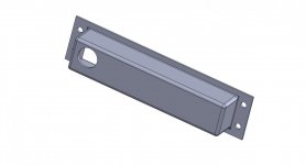
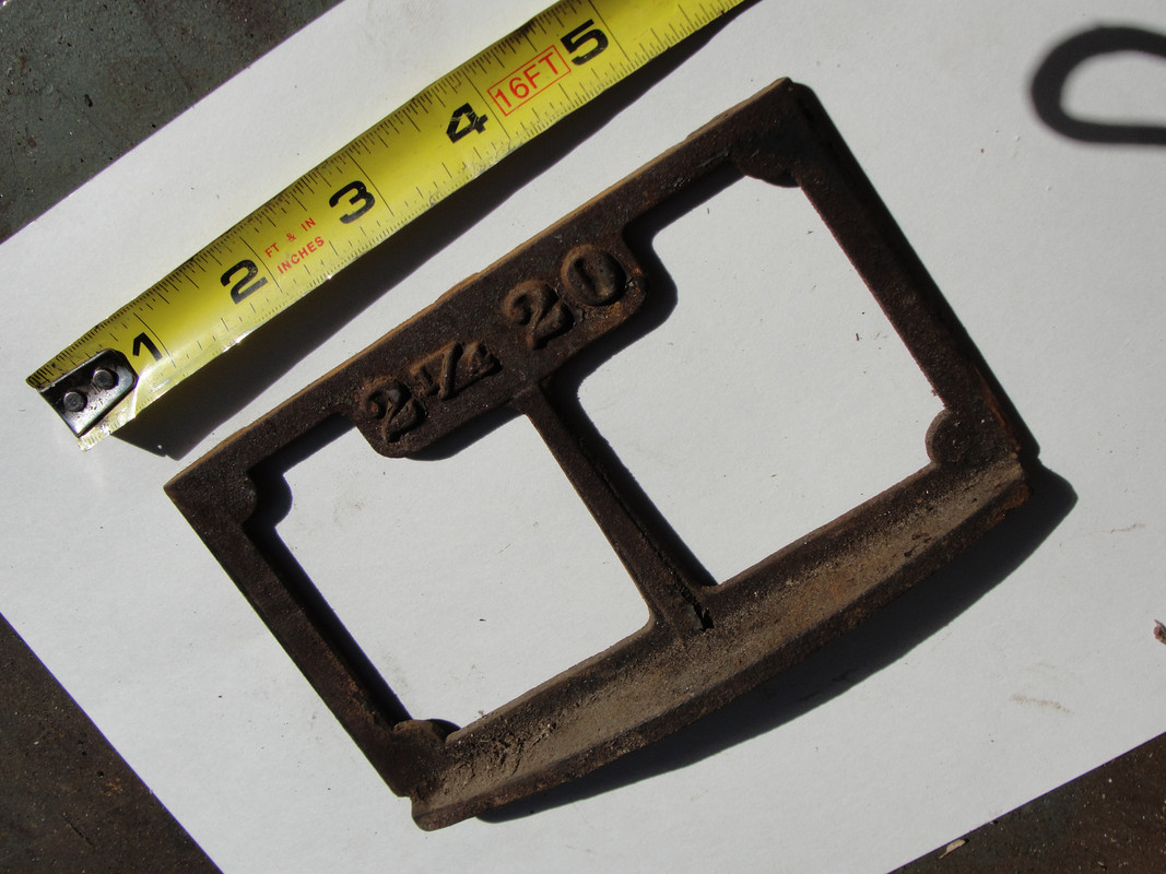
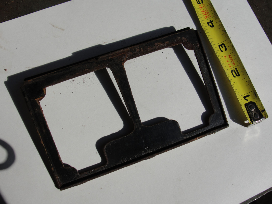
Show them drawing as received
Ask them to identify missing components (list form or measurement markings with ?) or incomplete information (hole in bottom measured off the outside or inside to center of circle)
Make list of optional improvements (bevel/chamfer, rounded/fillet, etc), I noticed some were already implemented in proposed rendering
Redo drawing to drafting specifications (measurements centered on holes, grouped, etc)
Start showing them 3D CAD software with this as the model


I am teaching 7/8th graders and we just started a week or two ago, diving into basic orthographic drawings and about to transition to basic 3D.

Robert, btw, the models 3D printers use are a watertight shell. So if I were to design something with essentially thickness, it would not even be able to be rendered as an .Stl. The average (plastic) 3d printer has a nozzle width of about .4mm and a layer height down to .05mm. I would never recommend going that thin for anything durable, but those are the tolerance limits for most "home-shop" 3d printers.

You may also want to think about the amount of stress (or lack thereof) this part may be under. ABS and PLA (the two most common 3d plastics) behave very differently.

Sent from my Phone 2 using The Garage Journal mobile app
 
Last edited:

Cruzan80

Well-known member
Joined
Jul 22, 2015
Messages
4,155
Location
Denver, CO
So, for the two classes (so far) out of the three I am teaching this to, it went well. We talked about why a "client" would specify things differently than we are used to drawing in CAD (maybe Robert only knows how much open space he has below, but doesn't care about the inside dimension), and how to use known references to be able to get to where they are comfortable.

Couple of questions I promised I would ask on their behalf...

First, the large circle in the dent looks centered in the drawing, but on the right, it says the center of the circle is .75" from the bottom edge (instead of 1"). They were wondering which way was correct.

Secondly, they were wondering what the .75 floating underneath the perspective drawing was on the right.


I also had them brainstorm what "suggestions" they would make to a potential client "for next time". The two overwhelming suggestions was to put a third drawing in (turn the bottom drawing 90deg right). This would allow for dimensions to be spread out further and have less confusion. The other suggestion was to standardize measuring from the center of a circle, or from the edge. The 1.5" vertical looks to be outside edge-to-edge, but the 1.375" at the bottom shows outside edge to center of circle.

Here is a quick CAD drawing we came up with in Fusion 360. For ease of measurement, we put the thickness at .1". Hope this helps.
 

Attachments

  • Car Part.pdf
    103.3 KB · Views: 31

Robert Haas

Well-known member
Joined
Sep 30, 2010
Messages
1,749
So, for the two classes (so far) out of the three I am teaching this to, it went well. We talked about why a "client" would specify things differently than we are used to drawing in CAD (maybe Robert only knows how much open space he has below, but doesn't care about the inside dimension), and how to use known references to be able to get to where they are comfortable.

Couple of questions I promised I would ask on their behalf...

First, the large circle in the dent looks centered in the drawing, but on the right, it says the center of the circle is .75" from the bottom edge (instead of 1"). They were wondering which way was correct.

Secondly, they were wondering what the .75 floating underneath the perspective drawing was on the right.


I also had them brainstorm what "suggestions" they would make to a potential client "for next time". The two overwhelming suggestions was to put a third drawing in (turn the bottom drawing 90deg right). This would allow for dimensions to be spread out further and have less confusion. The other suggestion was to standardize measuring from the center of a circle, or from the edge. The 1.5" vertical looks to be outside edge-to-edge, but the 1.375" at the bottom shows outside edge to center of circle.

Here is a quick CAD drawing we came up with in Fusion 360. For ease of measurement, we put the thickness at .1". Hope this helps.
Question # 1
"the large circle in the dent looks centered in the drawing, but on the right, it says the center of the circle is .75" from the bottom edge (instead of 1"). They were wondering which way was correct.?"

the outside dimension of the lower "box" is 1.500" and the center would be .75" so yes centered on the lower box is correct.

Question #2

A mistake from rendering that should have been picked up prior to uploading.
 

bdbecker

ALLIANCE MEMBER
Joined
Nov 18, 2015
Messages
5,542
Location
Iowa
Robert - could the face plate and box be made in separate pieces and glued together? That would make it much quicker/easier to print because it would get rid of the need for supports during the print process.
 

Robert Haas

Well-known member
Joined
Sep 30, 2010
Messages
1,749
Robert - could the face plate and box be made in separate pieces and glued together? That would make it much quicker/easier to print because it would get rid of the need for supports during the print process.

no reason it couldn't be 2 piece.
 

penright

ALLIANCE MEMBER
Joined
Dec 27, 2016
Messages
618
Location
SW of Mustang, OK
Finally got the printer sorted out after upgrading to Ender 3 Dip and BL Touch clone. Teaching Tech calibrating web site helped a lot.
I also got the bench area pulled together with a pegboard on the back above the bench.
Here is a picture showing several projects.

ACtC-3cmmHQI9xmrxP4eL-q1b6XjDB7xNXHrdSMloGL5iZX08RR7D0NslZETgweImJc3zqgdFum0aYIQEr2CPxLrOl9LxH_c5rpxMzPflovZDHwz9vhbc-FjbbFYNWP5EStTrvLE8jBwSe9K6cQxQlPDYghr=w502-h669-no


The phone charged is one that I really like. The lesson learned between when I did the metric vs imperial. By making the ramp steeper, they use less space. Also, I changed the lips that the wrench hangs on. A lot less plastic, easier to model, and quicker prints.

This is how I am going to try my ratcheting end wrenches. I have not tried to model it yet. The fun is finding a way to tie them together and still keep pins on a 1" grid.

ACtC-3cCkecvVfgAieYwLTcO72oYhSmHLnur5D41R4UAa96L4jO05807reLrqGgp8O8LTff_ZRhC2ZXv5vJ16iPJzqubA_quVjPwsUU4JkmhFebzfBkZjNn6BJVMrPxOZdn1h7i5U06OVbApYnN1mocwNPyC=w502-h669-no
 

slim01

Member
Joined
Feb 6, 2010
Messages
23
Looks good mate, really tidies the space up. Spanner racks are something I need to get on to myself.
 

white91formula

Well-known member
Joined
Dec 11, 2012
Messages
424
Location
Boston, MA
Been busy making more organization stuff for my tools. Plenty more to come.
 

Attachments

  • Attach13090_20201122_103935.jpg
    Attach13090_20201122_103935.jpg
    156.4 KB · Views: 146
  • Attach13091_20201122_103935.jpg
    Attach13091_20201122_103935.jpg
    80.3 KB · Views: 132
  • Attach13092_20201122_103935.jpg
    Attach13092_20201122_103935.jpg
    86.5 KB · Views: 138

jfleisher

Well-known member
Joined
Dec 13, 2010
Messages
1,065
Location
Marysville, Ohio
Printed a few pliers holders for pegboard on my Ender 6 SE. Much more secure.
 

Attachments

  • 57B90AE0-C251-4668-941A-C0806BCE9A4B.jpg
    57B90AE0-C251-4668-941A-C0806BCE9A4B.jpg
    113.2 KB · Views: 132
  • 72C98FEF-C0DE-4DA2-8091-C2E6900679B9.jpg
    72C98FEF-C0DE-4DA2-8091-C2E6900679B9.jpg
    144.6 KB · Views: 135
To avoid these ads, REGISTER NOW!
Top Bottom