LutzTD,
Well I sat and looked at the code that came with the CircuitDigest Charlieplexing article for a half hour or so this evening and I fixed it. I won't say I figured it out because I don't really know what I'm doing. I am reasonably good with pattern recognition so, after watching the project run on the breadboard while studying the code, I thought I knew what would solve the out-of-sequence issue.
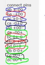
If the following is substituted for the same section of code in the CircuitDigest code, my project lights up the LEDs in the proper sequence.
int matrix[LED_Num][2][4] = {
// --------------PIN_CONFIG------------------PIN_STATE
// -----A---------B--------C-------D----------A------B-----C-----D
{ { OUTPUT, OUTPUT, INPUT, INPUT }, { HIGH, LOW, LOW, LOW } },
{ { OUTPUT, OUTPUT, INPUT, INPUT }, { LOW, HIGH, LOW, LOW } },
{ { INPUT, OUTPUT, OUTPUT, INPUT }, { LOW, HIGH, LOW, LOW } },
{ { INPUT, OUTPUT, OUTPUT, INPUT }, { LOW, LOW, HIGH, LOW } },
{ { INPUT, INPUT, OUTPUT, OUTPUT }, { LOW, LOW, HIGH, LOW } },
{ { INPUT, INPUT, OUTPUT, OUTPUT }, { LOW, LOW, LOW, HIGH } },
{ { OUTPUT, INPUT, OUTPUT, INPUT }, { HIGH, LOW, LOW, LOW } },
{ { OUTPUT, INPUT, OUTPUT, INPUT }, { LOW, LOW, HIGH, LOW } },
{ { INPUT, OUTPUT, INPUT, OUTPUT }, { LOW, HIGH, LOW, LOW } },
{ { INPUT, OUTPUT, INPUT, OUTPUT }, { LOW, LOW, LOW, HIGH } },
{ { OUTPUT, INPUT, INPUT, OUTPUT }, { HIGH, LOW, LOW, LOW } },
{ { OUTPUT, INPUT, INPUT, OUTPUT }, { LOW, LOW, LOW, HIGH } }
};
After doing that I started experimenting with the project a little more. The way this project is set up I assumed that one of the 2 LEDs on each "branch" would have to be ON and the other OFF.
Nope.
They both can be off but, so far, I don't think they both can be on.
Still goofing around with it.
Best regards,
Scott