To avoid these ads, REGISTER NOW!

The Machine Work Thread

To avoid these ads, REGISTER NOW!

bullnerd

Well-known member
Joined
Sep 17, 2012
Messages
5,690
Location
Jersey
Im interested in your power draw bar too. It looks a lot beefier than most of the internet designs. Can you show how you activate it?

I have a p-trak that is just dying for one of these.

Kaz, I saw your gimbal on IG, I didn't know that was you. Pretty cool.
 

NASTYZEN

Well-known member
Joined
Jun 11, 2010
Messages
2,823
Location
St-Colomban,Que. Canada
Last night I finished up my new power drawbar for my milling machine. I fabricated one when I first got my new mill but I saw one that a guy (Collin @ Comp Edge X) fabricated and really liked his design, so I copied it somewhat. I liked his design because it was so much more compact as he used the air cylinder in the "pull" fashion rather than "push" so I was able to keep the overall height much less. I also went and machined some of the brass fittings rather than used over the counter ones purchased from my local hardware store.

Completed unit and bolted on the mill. Looks and works awesome.
245y2xi.jpg

That is real sweet Mike.:thumbup:
I was wondering how I could reach the drawbar on my Comet after I enclose it. I like your design.
I will be leaning on you when the time comes to build mine.
Thanks for posting.
 

Kevin54

MEMBER EMERITUS
Joined
Jan 12, 2005
Messages
29,341
Location
Urbana, Ohio
I'll scan the drawings and shoot them to you. Sorry they are not CAD drawings and just hand written. Do you want part numbers for the check/needle valves, air cylinder, etc as well?

Mike.

If you have the numbers handy where you can jot them down or send them later. This is just what I need because I can't hold the brake and turn the wrench at the same time because I can't reach the brake with my left arm. I would really appreciate it immensely.

Still working on some details. This was before weighting the bottom and adding the camera. The rings pivot on .125 dowel pins with the hole reamed under on the outside and over on the inside so each part rotates freely. Just adding a dab of oil to each one. The center is a 6902 bearing so the camera can be pivoted about it's axis.

Thinking of launching a kickstarter aimed at GoPro/iPhone users. This whole stupid thing started with my brother wanting me to modify a cheap one that he bought, so I started just building the gimbal part. Ended up building a whole unit. Going to refine the design a bit, make it a bit more compact and better looking. Just wanted to see if it would work first. All built from scrap I had laying around.

Easier explanation:

https://vimeo.com/117300347

Now that it just super sweet. I wonder how it would act if you had a set of bearings out of some junk hard drives of some computers? Those are some super bearings that have nearly no resistance at all.
 

kazlx

Well-known member
Joined
Oct 30, 2012
Messages
2,851
Location
Tustin, CA
Now that it just super sweet. I wonder how it would act if you had a set of bearings out of some junk hard drives of some computers? Those are some super bearings that have nearly no resistance at all.

That's a good idea. The dowel pins work surprisingly well, especially for being inexpensive.
 

zmotorsports

ALLIANCE MEMBER
Joined
Oct 20, 2009
Messages
21,308
Location
Northern Utah
That is real sweet Mike.:thumbup:
I was wondering how I could reach the drawbar on my Comet after I enclose it. I like your design.
I will be leaning on you when the time comes to build mine.
Thanks for posting.

Claude, PM sent. Let me know if you have any issues reading the scanned drawings.

Are you interested in selling the plans to build one? If so, I would be interested in a set of plans.

Kevin, PM sent. Let me know if you have any issues reading the scanned drawings.

Thanks for the comments guys, I appreciate it.

Mike.
 

zmotorsports

ALLIANCE MEMBER
Joined
Oct 20, 2009
Messages
21,308
Location
Northern Utah
Is that a universal style or does it just fit
Specific machines ?

The top of my Taiwanese mill looks very similar to most of the other BP clones but I am not certain of the bolt pattern, nor am I certain about the bolt pattern on an actual BP mill.

The design/style should work universally once it is bolted to the top of the mill. The Kurt style uses a similar butterfly style pneumatic ratchet but it uses a larger canister style air chamber that pulls the air ratchet downward onto the drawbar. The Kurt is also fully enclosed with a cover and costs upwards of $1k dollars.

Mike.
 

NASTYZEN

Well-known member
Joined
Jun 11, 2010
Messages
2,823
Location
St-Colomban,Que. Canada
Thanks Mike,
Those drawings you sent will work. I'll make sure to check the hole pattern when I get there.
How does the air hookup work? What's the canister thingy and what does it do?:headscrat.
Need more shots of your setup.

What I really need is a holiday.

Thing a ma jigies I made lately.


Lots of the darn things..

 
OP
H

Hephaestus29

Well-known member
Joined
Mar 13, 2011
Messages
2,969
Location
Indianapolis
I'm going to look at a millport sat. With a
Bridgeport head, i might be interested
In your plans also. Very nice work by the way.
 

zmotorsports

ALLIANCE MEMBER
Joined
Oct 20, 2009
Messages
21,308
Location
Northern Utah
Thanks Mike,
Those drawings you sent will work. I'll make sure to check the hole pattern when I get there.
How does the air hookup work? What's the canister thingy and what does it do?:headscrat.
Need more shots of your setup.

No problem Claude. I didn't document the controls on this build because they were shown on my previous power drawbar. I have attached a link to the thread that shows my original setup. The canister is actually a pneumatic cylinder with a 1" stroke. On my original design the air cylinder was up on top and pushed downward on the assembly. This one the air cylinder mounts parallel to the impact gun and I used the opposite port of the air cylinder so it pulls the top place and impact down onto the drawbar.

It is on page 4 of my shop projects about half way down. Basically I removed the back half of the pneumatic butterfly impact gun and machined a block to bolt it to. That is what controls the air flow to the body of the impact gun on the top of the mill.

I hope that makes sense.

I also did a youtube video of it but my son is still editing it so it is not on my channel yet.

Mike.
 

zmotorsports

ALLIANCE MEMBER
Joined
Oct 20, 2009
Messages
21,308
Location
Northern Utah
I'm going to look at a millport sat. With a
Bridgeport head, i might be interested
In your plans also. Very nice work by the way.

If I can help you out shoot me your email and I can send you the drawings that I have. They aren't much, they are merely hand written drawings, wish I had a CAD program, but you are welcome to them.

Mike.
 

zmotorsports

ALLIANCE MEMBER
Joined
Oct 20, 2009
Messages
21,308
Location
Northern Utah
Last night I finished up my new power drawbar for my milling machine. I fabricated one when I first got my new mill but I saw one that a guy (Collin @ Comp Edge X) fabricated and really liked his design, so I copied it somewhat. I liked his design because it was so much more compact as he used the air cylinder in the "pull" fashion rather than "push" so I was able to keep the overall height much less. I also went and machined some of the brass fittings rather than used over the counter ones purchased from my local hardware store.

Here are my preliminary drawings for the base plate and top plate along with all of the ports and screw holes for the butterfly air gun.


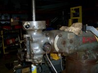
Top plate roughly layed out. I will get exact once I put it on my mill table and indicate off measurements exactly using the DRO.


Top plate machined to size and drilled/tapped for the butterfly air ratchet.


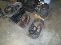
Bottom plate machined to size and drilled for the mounting location as well as the holes drilled and countersunk for the vertical guide rods. Also pictured are the guide rods.

Guide rods mocked into position. Bronze and brass in the background to be used for the bushings and the "tees" for the fittings.


Completed unit and bolted on the mill. Looks and works awesome.
245y2xi.jpg

If anyone is interested here are my two videos that I made while machining my new power drawbar.

Here is Part 1

Here is Part 2

Mike.
 

dcmus

Well-known member
Joined
Dec 19, 2011
Messages
331
Location
Ardmore, Ok
A great thread! A group I didn't see mentioned is madmodder.net an English group which is very cordial and welcomes newbys:)
 

bullnerd

Well-known member
Joined
Sep 17, 2012
Messages
5,690
Location
Jersey
Great job! Nice video and really clean shop!

It would be great to get a copy of that sketch. Once you go power you can never go back! LOL!
 
Last edited:
To avoid these ads, REGISTER NOW!

383 240z

Well-known member
Joined
Dec 4, 2006
Messages
4,295
Location
Findley Twp. Allegheny Co.
IMG_2058_zps0ydtw053.jpg

IMG_2059_zps7a4ixu93.jpg


Here is my latest project. These are made on a CNC lathe. Cycle time is 59 seconds each. It could be 43 seconds but the customer is super **** about burrs so there are a few extra de-burring passes in the program. The material is 316 stainless. I have no idea what they are, or what they are for, but I have to turn 90,000 of them!!! Keith


Sorry the pics are a bit out of focus, that is the best I could get with my phone in the poor lighting. Keith
 

Kevin54

MEMBER EMERITUS
Joined
Jan 12, 2005
Messages
29,341
Location
Urbana, Ohio
If anyone is interested here are my two videos that I made while machining my new power drawbar.

Here is Part 1

Here is Part 2

Mike.


ZEE......if you want a design program, look into DeltaCad. www.deltacad.com I have used it for quite a few years now and I love it. It's very simple to use once you get the main gist of what the icons are. And with your machining capabilities, I know it wouldn't take anytime for you to figure it out. They have a 30 day free trial, then it is something like $40. I bought it to use at work for designing tooling and turned a lot of others onto it. With your machines, and your machining capabilities, I think it could really benefit you to keep things on file. Just an idea and my $.02 worth on things. :thumbup:
 

zmotorsports

ALLIANCE MEMBER
Joined
Oct 20, 2009
Messages
21,308
Location
Northern Utah
ZEE......if you want a design program, look into DeltaCad. www.deltacad.com I have used it for quite a few years now and I love it. It's very simple to use once you get the main gist of what the icons are. And with your machining capabilities, I know it wouldn't take anytime for you to figure it out. They have a 30 day free trial, then it is something like $40. I bought it to use at work for designing tooling and turned a lot of others onto it. With your machines, and your machining capabilities, I think it could really benefit you to keep things on file. Just an idea and my $.02 worth on things. :thumbup:

Kevin, thanks for the info. I am definitely going to check that out.

I really appreciate that, as well as the compliment.

Mike.
 

Kevin54

MEMBER EMERITUS
Joined
Jan 12, 2005
Messages
29,341
Location
Urbana, Ohio
Kevin, thanks for the info. I am definitely going to check that out.

I really appreciate that, as well as the compliment.

Mike.

If you do download the 30 day trial and have any questions, let me know and I can walk you right through them. I have used a couple of different programs that we had at work, and it was either hard to use it to draw, or hard to use it to dimension. DeltaCad gives you the best of both. After a few days on it, it is a breeze to use. I can either walk you through questions on the internet or walk you through it over the phone on my dime.

And again.....beautiful work!!!!! I may have to put you right up there with A_PMech :thumbup:
 

zmotorsports

ALLIANCE MEMBER
Joined
Oct 20, 2009
Messages
21,308
Location
Northern Utah
If you do download the 30 day trial and have any questions, let me know and I can walk you right through them. I have used a couple of different programs that we had at work, and it was either hard to use it to draw, or hard to use it to dimension. DeltaCad gives you the best of both. After a few days on it, it is a breeze to use. I can either walk you through questions on the internet or walk you through it over the phone on my dime.

And again.....beautiful work!!!!! I may have to put you right up there with A_PMech :thumbup:

Thanks Kevin, I really appreciate that.

Trust me though, I am not in the same league as A_PMech though, but I appreciate the compliment.

Mike.
 
OP
H

Hephaestus29

Well-known member
Joined
Mar 13, 2011
Messages
2,969
Location
Indianapolis
I was thinking of buying a Jewelry Box/Chest for my instruments & small items like indicators, edge finder, etc. instead of an expensive machinist chest. I've seen all different kinds of them on Craigslist, mens & womens stained oak, painted black etc. some plain & some lined very nice on the inside for very reasonable money instead of a very expensive machinist chest.

Does anyone think I'm nuts or fruity for this ?
 

383 240z

Well-known member
Joined
Dec 4, 2006
Messages
4,295
Location
Findley Twp. Allegheny Co.
Is there not any Milling required in the turning operation or does your CNC lathe have milling capabilities too ?

If that was aimed at me, yes the Swiss machines have milling capability. I don't get a chance to run them often. I am able to make code changes, but in reality, I just monitor the parts coming off them, and call a programmer when I start getting near the tolerance limits.

I was moved off my regular machines because one was down with a dead clutch, my other machine was not wanting to repeat due to a problem with the stock stop cam.

I'll be back on them Monday. I have a neat jobs running on both of them. I'll post pics then. Keith
 
OP
H

Hephaestus29

Well-known member
Joined
Mar 13, 2011
Messages
2,969
Location
Indianapolis
If that was aimed at me, yes the Swiss machines have milling capability. I don't get a chance to run them often. I am able to make code changes, but in reality, I just monitor the parts coming off them, and call a programmer when I start getting near the tolerance limits.

I was moved off my regular machines because one was down with a dead clutch, my other machine was not wanting to repeat due to a problem with the stock stop cam.

I'll be back on them Monday. I have a neat jobs running on both of them. I'll post pics then. Keith
Kind of sounds like where I work, i just
mainly keep the parts on size, if anything
major needs to be reprogrammed they
call the engineer
 

coma13

Well-known member
Joined
Nov 5, 2012
Messages
247
122c785a5c0becdf8bf9c289bb3f8db7.jpg


f8d721b08d451bef252a1d2ceb7a44ec.jpg


This hardly warrants being posted in this thread, but I turned a little flange to extend an intake manifold I wanted to run on my shovelhead that was too small.
 

Duker

Well-known member
Joined
Sep 25, 2010
Messages
10,861
Location
Livingston, TX
If you do download the 30 day trial and have any questions, let me know and I can walk you right through them. I have used a couple of different programs that we had at work, and it was either hard to use it to draw, or hard to use it to dimension. DeltaCad gives you the best of both. After a few days on it, it is a breeze to use. I can either walk you through questions on the internet or walk you through it over the phone on my dime.

And again.....beautiful work!!!!! I may have to put you right up there with A_PMech :thumbup:

Kevin, we need you to join Mike in making some videos! :)
 

endmill

Well-known member
Joined
Dec 9, 2010
Messages
259
Location
nashport,Oh
Doing some TLC on my Bridgeport here is a series of youtube video that is great.
 

Attachments

  • 100_7335 (640x480).jpg
    100_7335 (640x480).jpg
    42.3 KB · Views: 181
  • 100_7336 (640x480).jpg
    100_7336 (640x480).jpg
    36.5 KB · Views: 177
  • 100_7337 (640x480).jpg
    100_7337 (640x480).jpg
    37.2 KB · Views: 174

Kevin54

MEMBER EMERITUS
Joined
Jan 12, 2005
Messages
29,341
Location
Urbana, Ohio
122c785a5c0becdf8bf9c289bb3f8db7.jpg


f8d721b08d451bef252a1d2ceb7a44ec.jpg


This hardly warrants being posted in this thread, but I turned a little flange to extend an intake manifold I wanted to run on my shovelhead that was too small.

Coma....any fabrication warrants being posted in the Fabrication Forum. You may not think it is much, but it may just be enough to give someone an idea that will save them some big money, or get the wheels turning for a project of their own. Simple or complicated, fabrication is fabrication, and no one should feel left out or that what they do is not worthy. Just something simple like removing a broken screw is worth enough to help many members out. And with a broken screw, there are a few ways to do it, but if no one answers a members question on how to possibly do it, then that person might have to shell out some big bucks. Ideas are ideas brother, and ideas are potential money savers :thumbup:

That is what this site is about.....helping others.....ideas or otherwise:rocker:
 

383 240z

Well-known member
Joined
Dec 4, 2006
Messages
4,295
Location
Findley Twp. Allegheny Co.
Here is what I've been making for the last few days.
IMG_2400_zpsgjs5sv8o.jpeg


It's a wear sleeve. They get heat treated then gets pressed into an aluminum part. An axle rides in them. I have no idea what the final assembly looks like. Made 8600 of them today. The tolerance on that part is +- .002 I am tired of making these teeny little parts. Keith
 

macgyver37

Well-known member
Joined
Mar 7, 2013
Messages
608
Location
Pittsburg, Kansas
Keith, I am kinda tired of working on big parts. Seems like all I have done the last couple months are parts that are bigger than my machine table.
I don't have a pic of them, but I ran 1030 ft of a profile cut out of 1 3/4" dia Nylatron bar stock. I machine a T shape out of the round. They of course are 10 ft long pcs and my table is only 8ft, so I made some extensions and such to get the done.
I also just got done making 400 ft of UHMW chain guides like the curved pcs I showed earlier in the thread, they are also 10 ft long.

Another over 8ft long part I did was these black pcs, they are just over 9ft at 112" long. This particular part used repro UHMW as it was on the waste side of the poultry plant line and didn't need to be food safe. This particular one they gave me the gray one as a sample and I had to measure it and go from there. This one I was able to go diagonal on the table and cut it that way.
 

Attachments

  • 0602141839a.jpg
    0602141839a.jpg
    145.5 KB · Views: 138
  • 0602141838.jpg
    0602141838.jpg
    153.2 KB · Views: 112
  • 0602141839.jpg
    0602141839.jpg
    148.8 KB · Views: 113
  • 0602141839b.jpg
    0602141839b.jpg
    145.5 KB · Views: 115
  • 0602141840.jpg
    0602141840.jpg
    147.3 KB · Views: 106
  • 0602141840a.jpg
    0602141840a.jpg
    161 KB · Views: 107
To avoid these ads, REGISTER NOW!
Top Bottom