
You are using an out of date browser. It may not display this or other websites correctly.
You should upgrade or use an alternative browser.
You should upgrade or use an alternative browser.
The Machine Work Thread
- Thread starter Hephaestus29
- Start date
kazlx
Well-known member


kazlx
Well-known member
^ Those are some nice big chips, what endmill and ipms/doc/woc were you using there?
3/4" endmill (2.25" LOC), 0.5" DOC, 0.3WOC, about 9000 RPM, 100IPM. The raw stock for the flange was 7x7 and 2" thick. Could definitely go more, but only making the one piece. I had the endmill already loaded for another part I made where I needed the length.
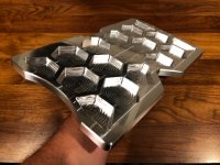
The small bowl is just testing some finishes on tool paths. It's about 1.5" wide and .45 deep. Roughed with 1/4 3fl square and finished with a 1/4 3fl ball.
Last edited:
3/4" endmill (2.25" LOC), 0.5" DOC, 0.3WOC, about 9000 RPM, 100IPM. The raw stock for the flange was 7x7 and 2" thick. Could definitely go more, but only making the one piece. I had the endmill already loaded for another part I made where I needed the length.
The small bowl is just testing some finishes on tool paths. It's about 1.5" wide and .45 deep. Roughed with 1/4 3fl square and finished with a 1/4 3fl ball.
Haha
 those are crazy numbers to me! One of these days I'm gonna stop by!
kazlx
Well-known member
Haha
Anytime!
kazlx
Well-known member
20 year old Fadal. I'll take it.

I thought this was going to be the ultimate dog bowl. Still cool though.
kazlx
Well-known member
That last one is for a mouse haha. It's only 1.5" across. Just a test on some surfacing that a dude posted on Instagram to try out.
The other flanges are for my parent's trailer table and are ~7" across and 2" thick.
The other flanges are for my parent's trailer table and are ~7" across and 2" thick.
Griff93
Well-known member
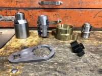
Made a cylinder mount for a piece of equipment we're repairing in the shop. This started out as a piece of 1.25 plate 5"x5". The cutout at the bottom goes on a piece of 2" square 1/4" wall tube.
 2019-02-13_08-37-54 by Griffin93, on Flickr
2019-02-13_08-37-54 by Griffin93, on Flickr
Last edited:
whateg01
Well-known member
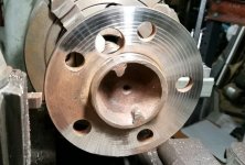
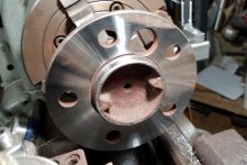
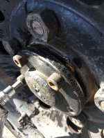
Well, it's not as cool as the stuff the computer makes, but it's still pretty satisfying. My dad and brother are restoring a '67 Coronet R/T and Dad's adding disc brakes. The kit is supposed to fit the axles, but didn't quite, so I took the axles home and turned them down to work. My brother, trying to get one of the axles out, used the biggest hammer he could find before Dad pointed out one retaining bolt still in place. So, the axle flange was not flat anymore. It had 0.038" TIR axially. I ended up facing both the front and back of the flange to try to keep it in balance as much as possible.
It's not the best finish in the world, but it's flat, and that was what mattered. I only took about 0.005" per pass the last couple passes, trying to sneak up on "good enough". If I would have taken a bigger bite, it would have left a better finish. The second axle was nicer.
I took a skim cut on both faces of the other axle too, even though it only had about 0.016" TIR axially.
Here you can see the main spot where he was beating on the axle.

This was after taking 0.010" off.

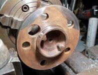
With 0.020" taken off, you can clearly see both spots where he was hitting the flange.

I stopped here since I had good contact over more than 3/4 of the way around. Another 0.005" would have cleaned it completely, but I didn't feel good about taking more material off.

I only took 0.010" off the other axle and it cleaned up except for one spot along the edge.

Dave
It's not the best finish in the world, but it's flat, and that was what mattered. I only took about 0.005" per pass the last couple passes, trying to sneak up on "good enough". If I would have taken a bigger bite, it would have left a better finish. The second axle was nicer.
I took a skim cut on both faces of the other axle too, even though it only had about 0.016" TIR axially.
Here you can see the main spot where he was beating on the axle.
This was after taking 0.010" off.
With 0.020" taken off, you can clearly see both spots where he was hitting the flange.
I stopped here since I had good contact over more than 3/4 of the way around. Another 0.005" would have cleaned it completely, but I didn't feel good about taking more material off.
I only took 0.010" off the other axle and it cleaned up except for one spot along the edge.
Dave
Attachments


Last edited:
That last one is for a mouse haha. It's only 1.5" across. Just a test on some surfacing that a dude posted on Instagram to try out.
The other flanges are for my parent's trailer table and are ~7" across and 2" thick.
I thought that looked familiar, had the same one on our last RV.
Griff93
Well-known member
Sometimes things just don't go right. That was not a step drill to begin with.
 2019-03-12_07-18-01 by Griffin93, on Flickr
2019-03-12_07-18-01 by Griffin93, on Flickrwhateg01
Well-known member
Sometimes things just don't go right. That was not a step drill to begin with.
Man I hate when that happens. Last time I ran into that was a piece of 1/4" should have been HRS, but was hard enough it dulled a carbide drill. Friend annealed it in his heat treat oven and then it was soft as butter. Still have no idea what that really was.
Dave
kazlx
Well-known member


")
kazlx
Well-known member
kazlx
Well-known member

NASTYZEN
Well-known member
There's a lot of times I look back and surprise myself with how much I've learned over the last couple years. If I can do it, anyone can. I love making stuff.
So true. I look at some of my early programing and have a good laugh at times at some of the goofy stuff I did. Oh man the learning curve!
Your work is top notch Kaz.
Can't say I didn't warn you way back when you got yourself a plasma that cnc was dangerously addictive.NASTYZEN
Well-known member
Oh yeah, I almost forgot. Go check out Titan at Titans of cnc or Titans of cnc academy The man is an inspiration and an endless source of knowledge.
The feeds and speeds this guy demonstrates and teaches in absolutely insane!
The feeds and speeds this guy demonstrates and teaches in absolutely insane!
kazlx
Well-known member
Thanks! I think that's what I love so much about it. It's literally a never ending pool of learning. The basic concepts and methods are pretty simple. There's just something so satisfying to watch anything take shape, from machining to welding to 3D printing. I still remember being so excited cutting a square on my cnc plasma table. It's definitely addicting...there's not enough time in the day.
kazlx
Well-known member
Oh yeah, I almost forgot. Go check out Titan at Titans of cnc or Titans of cnc academy The man is an inspiration and an endless source of knowledge.
The feeds and speeds this guy demonstrates and teaches in absolutely insane!
I follow his stuff. I'm a junkie. I read and watch vids and ask questions. I try to learn as much as I can and apply it. I seriously love the Fadal and the doors that it's opened. I wish this was the machine I had purchased in the first place like I originally wanted to. But I was scared. It all worked out though, but I'm already bumping into limitations on the Fadal. It's a great machine, but semi limited on speeds. I think the controller can only process so fast. I tried running the first op on the cubes at 120ipm since there's almost no material removal, .9 part coming from a 1" cube. They came out like a parallelogram. Slowed down to 60ipm and was within 0.0002 of programmed size. I have my eyes on a Brother Speedio at some point....
NASTYZEN
Well-known member
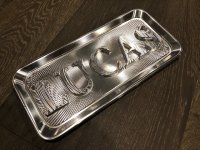
A test piece I made when testing out my new cnc mill 10 years ago. Made from a picture of my wife in the kitchen. I wish I had time to mess with artsy stuff. To busy producing these days. Good problems!
.035 ball mill 3500rpm. Took a long time.. I have a 10k router setup that slips over the main spindle via an adaptor that would go much faster. Maybe when I retire.

.035 ball mill 3500rpm. Took a long time.. I have a 10k router setup that slips over the main spindle via an adaptor that would go much faster. Maybe when I retire.
Last edited:
This was a quick one. I just assembled my first AR lower and saw this cool assembly fixture on a video. The lower part goes in your bench vise and the upper slides into the AR lower where the magazine goes. It was a huge help getting some of the tiny springs installed, many requiring 3 hands if one is holding the lower. Fun to machine plastic.

Bigblue&Goldie
Well-known member
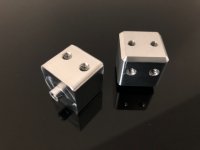
I finally got my Bridgeport up and running today, so I took her on a maiden voyage. I've been wanting some smooth faced jaws for one of my vises, so I thought this would be a good exercise to get my feet wet as it's been over a year since I've run a machine. I also have limited tooling at this point, so I had to counter bore with an endmill and relieve the edge with a chamfer tool.


Last edited:
kazlx
Well-known member


KBigg
Well-known member

jymmiejamz
Active member
I didn't want to post a new thread for this and thought this might be the best place for it. Would anyone in here be interested in a small project? I need to spacers for some Land Rover axle shafts made. I have the shafts but don't have the spacers that came with them (the company that made them has been out of business for years). The owner of the company sent me the specs for the spacers. Let me know if any of you wants to take on the job. I'm happy to pay for the work and materials.
I have attached a photo of why the spacer is needed, and also the dimensions of the spacer.
I have attached a photo of why the spacer is needed, and also the dimensions of the spacer.
Attachments
I didn't want to post a new thread for this and thought this might be the best place for it. Would anyone in here be interested in a small project? I need to spacers for some Land Rover axle shafts made. I have the shafts but don't have the spacers that came with them (the company that made them has been out of business for years). The owner of the company sent me the specs for the spacers. Let me know if any of you wants to take on the job. I'm happy to pay for the work and materials.
I have attached a photo of why the spacer is needed, and also the dimensions of the spacer.
So looks like the spacer will go in the gap shown in the pic and the center part of the spacer will be hollow so the axle shafts go through it? Probably a 4.5"x4.5" mild steel plate 1/2" thick stock will work for this.
Seems like a pretty straight forward project for either a CNC mill or a manual lathe. We have a bunch of guys here who can knock this out for you. If I wasn't knee deep in other things I'd do it.
I didn't want to post a new thread for this and thought this might be the best place for it. Would anyone in here be interested in a small project? I need to spacers for some Land Rover axle shafts made. I have the shafts but don't have the spacers that came with them (the company that made them has been out of business for years). The owner of the company sent me the specs for the spacers. Let me know if any of you wants to take on the job. I'm happy to pay for the work and materials.
I have attached a photo of why the spacer is needed, and also the dimensions of the spacer.
Out of curiosity, how long are the splines on the axle? If shortening the axle is an option 5 min with a grinder/cut off wheel and you're done.
jymmiejamz
Active member
So looks like the spacer will go in the gap shown in the pic and the center part of the spacer will be hollow so the axle shafts go through it? Probably a 4.5"x4.5" mild steel plate 1/2" thick stock will work for this.
Exactly. The drive flange is part of the shaft.
Out of curiosity, how long are the splines on the axle? If shortening the axle is an option 5 min with a grinder/cut off wheel and you're done.
That's actually a good question, but I'm assuming they are built this way for a reason. These HD shafts were made by a company called Rovertracks. While they are long out of business, the owner was kind enough to send me to drawings for the spacer. I know the shafts themselves were made by Moser.
paranoid56
Well-known member
Exactly. The drive flange is part of the shaft.
That's actually a good question, but I'm assuming they are built this way for a reason. These HD shafts were made by a company called Rovertracks. While they are long out of business, the owner was kind enough to send me to drawings for the spacer. I know the shafts themselves were made by Moser.
are each shaft the same length? how about the stock ones? ie, is the diff offset?
i cant think of a reason to build them long unless it was some sort of one size fits them all. but then i would have just made the splines longer so you could cut them down yourself.
are each shaft the same length? how about the stock ones? ie, is the diff offset?
i cant think of a reason to build them long unless it was some sort of one size fits them all. but then i would have just made the splines longer so you could cut them down yourself.
I was thinking that too. Unless they fit multiple diffs/models etc why not build them the right size and not deal with spacers.
@Firstram made a good point, if you have long enough splines (compare it with the OE ones) you can just chop the extra length off and you're good to go.
Fixing the AXA toolpost mount issue. Details on the issue are here:
https://www.hobby-machinist.com/thr...e-tool-post-due-to-grizzlys-poor-design.77904
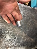
I decided to knurl the bottom of the stud as LMS suggested. The only problem was I couldn't do the knurling on the lathe...or could I?
Folks don't try this at home...but I couldn't come up with a better option

At 120 RPM and using my (now tired) fingers to push the tool into the stud for a good 30 mins I thought I had enough of a knurl to give it a try...and wow to my surprise I couldn't beat it into the hole with a small hammer. I put red loctite on it, grabbed a bigger hammer and a punch and set it into it's place

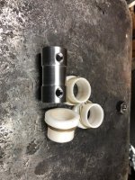
I was able to tighten the AXA TP fairly well at this point but I didn't want to overdo it until the loctite was dry. But I had my lathe back and I wanted to back up my work by driving an allen head into the hollow center of the stud sleeve. So I chucked up an appropriate sized bolt. Turned it down to about .04" oversized. Knurled it and then pressed it in with red loctite.

It was a very tight fit, I was afraid it might splay the hollow top so I threaded the nut around it...which later had a slight bit friction but not bad.


It's fully seated

A quick test and all seems well.

https://www.hobby-machinist.com/thr...e-tool-post-due-to-grizzlys-poor-design.77904
I decided to knurl the bottom of the stud as LMS suggested. The only problem was I couldn't do the knurling on the lathe...or could I?
Folks don't try this at home...but I couldn't come up with a better option
At 120 RPM and using my (now tired) fingers to push the tool into the stud for a good 30 mins I thought I had enough of a knurl to give it a try...and wow to my surprise I couldn't beat it into the hole with a small hammer. I put red loctite on it, grabbed a bigger hammer and a punch and set it into it's place
I was able to tighten the AXA TP fairly well at this point but I didn't want to overdo it until the loctite was dry. But I had my lathe back and I wanted to back up my work by driving an allen head into the hollow center of the stud sleeve. So I chucked up an appropriate sized bolt. Turned it down to about .04" oversized. Knurled it and then pressed it in with red loctite.
It was a very tight fit, I was afraid it might splay the hollow top so I threaded the nut around it...which later had a slight bit friction but not bad.
It's fully seated
A quick test and all seems well.
whateg01
Well-known member
Fixing the AXA toolpost mount issue. ...
You solved a problem, so good on ya for that. I guess I don't understand what the compound looks like on that lathe. Every lathe that I've dealt with uses a T-slot for the tool post to bolt down to. So, a T-bolt is made or a T-nut is used. Does your lathe not have that as an option? Seems like you went the hard way around without understanding more about it.
Dave
Dave, no T-nut setup unfortunately, just a round hole on the underside of the compound that the stud goes through. Here's the replacement stud for it, hope that clarifies it a bit?
https://www.grizzly.com/parts/Grizzly-TOOL-POST-STUD/P4000908
ClappedOutBport
Well-known member
- Joined
- Mar 30, 2016
- Messages
- 998
Wow. Grizzly does not impress here.
whateg01
Well-known member
Dave, no T-nut setup unfortunately, just a round hole on the underside of the compound that the stud goes through. Here's the replacement stud for it, hope that clarifies it a bit?
https://www.grizzly.com/parts/Grizzly-TOOL-POST-STUD/P4000908
I see. Just did some searching on Grizzly lathes and I found a video showing modifying the compound to hold a threaded stud, which seems a better, if more permanent, solution.
If there is enough material, I might even consider milling a slot in the bottom that a bolt head can sit in.
Wow. Grizzly does not impress here.
I agree! That's a pretty crappy design in my books!
Dave
Wow. Grizzly does not impress here.
Yep, and IMHO it was really holding the lathe back, which otherwise is not a bad lathe for the money. Anything but very shallow cuts would tend to move the tool post because of the poor design. The same but older models (like from 10yrs or so ago) had a splined bottom stud (similar to the knurling I did).
I see. Just did some searching on Grizzly lathes and I found a video showing modifying the compound to hold a threaded stud, which seems a better, if more permanent, solution.
If there is enough material, I might even consider milling a slot in the bottom that a bolt head can sit in.
Got a link to the video?
I was thinking about a roll pin (some other lathes do that) but there wasn't enough meat on the stud head to drill a 1/8" hole. I even started cutting a keyway slot but then what I ended up doing was the quickest solution if perhaps not the most elegant one.