Bigblue&Goldie
Well-known member
None of the above lol. Rigid tapping. I just run taps in ER collets.
What's an "ER" collet?

None of the above lol. Rigid tapping. I just run taps in ER collets.
None of the above lol. Rigid tapping. I just run taps in ER collets.

It’s just a type of collet. Same as an R8 or whatever. Just a different style. They come in a bunch of different sizes and have a grip range of like .100. They are very common for holding tools in CNC machines. So you need the tool holder with the correct taper for your machine, mine is Cat40 which is also super common. Then you buy the correct collet size both to fit the holder and to fit the tool you put in it.
https://www.maritool.com/Tool-Holders-CAT40-ER-Collet-Chucks/c23_25_42/index.html
Gotcha. With the CNC does the tap "pull" itself down like it does when power taping in a chuck or collet on a Bridgeport?
Gotcha. With the CNC does the tap "pull" itself down like it does when power taping in a chuck or collet on a Bridgeport?
No, not like a tap matic or free handing on a Bridgeport. The thread pitch is used to calculate the feedrate for the z axis (or whatever axis) and the tap is powered in and out. It is "rigid" the whole time.
But it depends if the CNC supports Rigid Tapping. CNC by itself doesn't automatically mean Rigid Tapping can be done. Which is what I was trying to say earlier that in a non-Rigid tapping senario it's the same as a manual mill.
I've seen that, but I know he has a big Fadal machine. I would like to get a Tapmatic tapping head for the Bridgeport, but I'll just powertap out of a drill chuck for the time being.
I have a VFD on my drill press for power tapping (its a 20" Clausing if that matters). Here's how it works.
- selector switch for Drill/Tap mode. In Drill-Mode the spindle runs clockwise/forward rotation and the control pot is used.
- In Tap mode the spindle runs in Reverse/counterclockwise and I dial it down to around 8Hz. Tap is just chucked by friction just like a drill bit. There's a footpedal so when you want to start tapping you grab one of the tri-handles and step on the pedal. The spindle ramps to a stop, then reverses direction to the correct one for tapping a right hand thread. So enter the tap into the work and apply light downpressure. When I have sufficient depth I step off the pedal and the tap backs itself out.
Its a simple parameter setup using one of the VFD's inputs and its low-voltage power supply. The footpedal is a signal to tell the VFD to change rotation direction.
This works very well when there's a pile of parts to be tapped.
For one hole, usually in a Bridgeport I just chuck the tap immediately after drilling the pilot hole because the alignment is never going to get better than that. Put the spindle back-gear lever in Neutral and use one hand to power-twist the exterior of the chuck and the other to apply light downpressure to the spindle. Once started one can use 2 hands on the spindle-twist. It works well up to about 1/2-13 or for tapered taps where its hard to get sufficient torque and then a spring-loaded tap guide and longer tap handle should be used. I've done guessing 5000 holes this way. Stock up on spiral-point "gun" taps and save the 4 fluters for when you need a bottoming tap all the way to the bottom of a blind hole.
Do you have capacitors to soak up the energy when you reverse the spindle? What is your ramp down rate (how many seconds)?
Do you have capacitors to soak up the energy when you reverse the spindle? What is your ramp down rate (how many seconds)?
My Bridgeport is 3 phase via VFD, so I really shouldn't be doing too much instant reversing. On through holes it's not a big deal as I can shut the machine down and apply the brake, but on blind holes I really don't want to chance it.
Reversing with the VFD puts the heat into the resistors, but I think reversing with a drum switch puts the heat into the motor.
Keep in mind the VFD is pushing out energy to a load which is sinking it, in an instant the energy has nowhere to go. In the next instant its opposed by the back-emf of not only a stationary motor but one spinning the opposite direction.
Think in mechanical analogy, you're pushing snow with a pickup truck. Then you hit a medium duty snowplow blade head-on which you then find medium duty truck was coasting at you in the opposite direction and so eventually you can reverse its direction. Can the pickup truck take this? Probably for awhile and depending on the mechanical inertia behind the truck. But you can see how it can shorten the life.
The thing saving the enterprise is the low amount of horsepower that a manual machine tool requires. But get to rated hp capacity and try that you will be buying a new VFD.
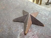
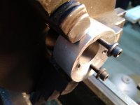
I had to figure out how to hold three dimensional cast iron stars so I could drill and tap the back of them for mounting. I was building a folk art flag, so I needed a bunch of them! The shape doesn't lend itself to holding easily, so I made a simple fixture. I had a piece of aluminum with a 1" hole. I bored/faced an angle to match the starts, which are about 23 degrees. I put in three tapped holes, and was going to make a cover plate to hold it, but #10 screws with washers clamped it fine. I could only use two of the holes due to variations in the stars, but it held them nice and solid. Clamp it up, spot, drill, tap, and repeat. I could have made a much more sophisticated fixture at work, but in the barn, you use what you've got.
^
Pretty cool! Not following how you milled it though; was it done on a 4-axis cnc mill?
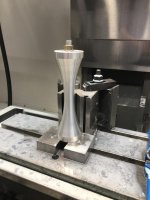
Noooo, everything except the holes I drilled and tapped was done on a cnc lathe. I could have done it in the 4th axis but it would have taken forever. It was just an odd setup I felt like sharing.
 I'm always curious how and what something was made on lol
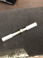
I made one of these fun captive nut puzzles the other day. Fun little project.
I made one of these fun captive nut puzzles the other day. Fun little project.
I like it.
Did you use studs in the stars then put a nut
and lock washer on the back of the board or?
So what's the secret behind this one? The rod threads into one of the end pieces?


")