To avoid these ads, REGISTER NOW!

The Original "Cordless" Drills

RTM

Well-known member
Joined
May 13, 2019
Messages
13,359
Location
SF Bay Area
dang, thought I replied the other morning, guess it got lost in hell.

Mine is just a plain set screw, screwing directly to the shaft visible thru the hole. I believe the shaft is split above and below the bearing. When the top shaft is locked, the quill is extended by unthreading from the bearing. But that would imply losing the flywheel effect, which does not seem right.
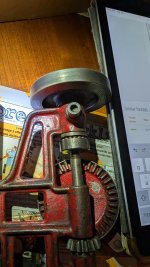
PXL_20260602_140625889-X2.jpg


Looking at yours, I’d assume the quill advances by extending out the fine thread, which I’m guessing might even be 2x the coarse thread.
 
To avoid these ads, REGISTER NOW!

Old tool guy

Well-known member
Joined
Apr 13, 2023
Messages
3,426
The fine thread is only there for the chuck to screw on. It’s the style where, as you screw the chuck on further it pushes the fingers out to grip the bit.
 
  • Sad
Reactions: RTM

RTM

Well-known member
Joined
May 13, 2019
Messages
13,359
Location
SF Bay Area
Instill don’t understand how the self feed works, maybe it will become evident when it’s all assembled and moving easily.
Ok, since I've never had mine apart, I'm assuming your coarse thread on the shaft screws into the hollow shaft sticking out of the flywheel. And the spring on the locking screw rides in the groove on the hollow shaft. You need to thread the dual thread shaft all the way up into the flywheel to start. When you want it to self feed, tighten the screw, and stop the flywheel. Then, as you continue to crank, the shaft will unscrew from the hollow shaft on the flywheel. I think you need to crank it backwards to retract the quill.

My thought of a split shaft earlier might actually be the same as yours, a hollow shaft at the outlet end.

I assume to drill without the auto feed, you might just loosen the screw that holds the head on the shaft, and let gravity win.
 

four.cycle

Well-known member
Joined
Oct 19, 2015
Messages
29,592
Location
Tacoma, Washington
Wow.... I guess I have some reading to do here. This is the first time I've looked at this thread.
For reasons I still don't understand, I acquired about half a dozen of these about a year ago - Stanley, Millers Falls, etc.
They're all in a box in the garage waiting for me to get to them.
 

Old tool guy

Well-known member
Joined
Apr 13, 2023
Messages
3,426
Ok, since I've never had mine apart, I'm assuming your coarse thread on the shaft screws into the hollow shaft sticking out of the flywheel. YES

And the spring on the locking screw rides in the groove on the hollow shaft. Could be, it lines up that way. Probably a ball bearing, not the bare spring.
You need to thread the dual thread shaft all the way up into the flywheel to start. When you want it to self feed, tighten the screw, and stop the flywheel. Then, as you continue to crank, the shaft will unscrew from the hollow shaft on the flywheel. I think you need to crank it backwards to retract the quill.

My thought of a split shaft earlier might actually be the same as yours, a hollow shaft at the outlet end.

I assume to drill without the auto feed, you might just loosen the screw that holds the head on the shaft, and let gravity win.
Appreciate your comments, getting close to final assembly.
Here’s an interesting detail, looks like an oil port to drip oil on the ball bearings and maybe the shaft. But it sure is tucked up high under the flywheel. Sure wish the manufacturer had a website …
.
IMG_3643.jpeg
 

Old tool guy

Well-known member
Joined
Apr 13, 2023
Messages
3,426
Got it! I guess if i was a decent guy i would post a short video.
.
So here's the deal. If the set screw under the flywheel is loose, the flywheel turns with the shaft and crank, providing some inertia. Not sure what the purpose is, unless you had a burr or wire brush or something you wanted to spin, and hold material against it. I put a 1/4” ball bearing at the end of the spring which will get pressed against the extended shaft of the flywheel. When you tighten the set screw, it applies enough pressure to prevent the flywheel from turning, and then the coarse threads at the top of the shaft ride up & down the internal threads of the flywheel, causing the quill to rise and fall (depending on which way you are turning the crank).
.
Maybe you would loosen the setscrew, get the quill up to speed, tighten the setcscrew to lower the bit into the material with some speed and inertia.
 

Old tool guy

Well-known member
Joined
Apr 13, 2023
Messages
3,426
Chucked a bit into it and started playing around, found an interesting feature. Leave the set screw loose, crank the handle to get up a little speed, then use your hand to slow the flywheel. That causes the quill to start lowering into the wood or part to be drilled. If the drill bogs down, let go of the flywheel, stops advancing the bit, regain some speed.
 

four.cycle

Well-known member
Joined
Oct 19, 2015
Messages
29,592
Location
Tacoma, Washington
I dug all these out yesterday and cleaned them up as best I could with the tools at hand. My grinder boy machine is down, so no wire wheel - just hand brushing and a little "Dremel" tool. Nothing really special or rare here. The Millers Falls No. 2 is the star of the lot.
The "G.M. Mfg. Co." unit is actually nicely made - far better than their socket sets.
hand drills (eggbeater) 07216.jpg
L to R: unmarked, Stanley, Fulton, G.M. Mfg. Co., Millers Falls No. 2, unmarked breast drill 07/21/26
 
To avoid these ads, REGISTER NOW!

59Sled

Well-known member
Joined
Sep 22, 2025
Messages
170
Location
Santa Clarita, California
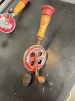
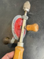
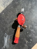
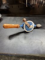
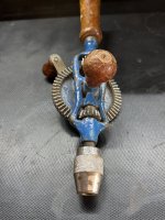
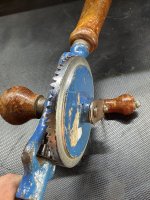
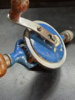
Well I went back to the antique malll and picked this one up. Been there for a few months. I originally passed on it because it looks like someone machined the outer lip of the big gear. Just didn’t look factory.
But I had so much fun restoring the other 3 I
did.
So I grabbed it since the price was right And for the fact. The life of me I can not find another one like this. There’s no writing on it. Plus the main body tappers in. Only seen this on breast drills. Plus it being blue. It does look like it had a sticker on the wood handle and a sticker on the big gear at one point.

Either way it’s different so I grabbed it.

If anyone has an idea who made it. Let me know. Part of the fun of old tools is the history on them.

IMG_0949.jpegIMG_0951.jpegIMG_0952.jpegIMG_0953.jpegIMG_0950.jpeg
 

59Sled

Well-known member
Joined
Sep 22, 2025
Messages
170
Location
Santa Clarita, California
Record (made in England) tools were often blue, although I recall seeing the name in raised letters on the large gear.
That’s what I thought it was originally. But the Record ones I see the main body where the gears are is square and blocky. Stanley also made a few blue ones. But thei main body is just a single metal shaft.
This is the one thing I like with vintage tools. Tracking down the history is fun.
 

RTM

Well-known member
Joined
May 13, 2019
Messages
13,359
Location
SF Bay Area
The life of me I can not find another one like this.
Here is a wild guess from the bleachers beyond left field.

Maybe this is a Franken drill. This assertion is based on flipping thru Randy's oldtoolheaven website, and this observation.

Any drill that has a solid main gear wheel does not have a fancy open frame like yours.

I don't have easy access at hand to any Stanley literature like the MF compilation that Randy did, or Record, or anyone else, so take this as a guess, and maybe a place to focus.

Your main body looks like it could belong to a GP / MF 4-1/2 drill, as seen here.


¢¢
 

RTM

Well-known member
Joined
May 13, 2019
Messages
13,359
Location
SF Bay Area
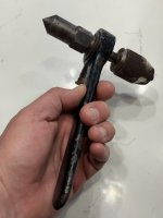
Don’t think i have seen one of those with the point on top. Makes it a little difficult to push down on it.
That's the beauty of that, that does the pushing for you. As you ratchet the bit forward, the pointy end moves away backwards, providing the forward push, and stopping you from impaling your hand.
 

59Sled

Well-known member
Joined
Sep 22, 2025
Messages
170
Location
Santa Clarita, California
Don’t think i have seen one of those with the point on top. Makes it a little difficult to push down on it.
I bought it because it was odd and didnt know exactly what it was. And that is was Goodell Pratt so I knew it was really old.

This is what some explained to me about the point.

It’s designed to assist when boring holes in metal, the tip would be placed in a drill press quill/lathe tailstock/drilling machine/etc. to apply direct pressure on the tool while the user ratcheted the handle. They are cool looking, and not especially common to run across any more. On this model the ratchet mechanism just turns whatever bit is in the chuck, advancing the feed screw is a separate operation with a wrench.

IMG_7619.jpeg
 

RTM

Well-known member
Joined
May 13, 2019
Messages
13,359
Location
SF Bay Area
On this model the ratchet mechanism just turns whatever bit is in the chuck, advancing the feed screw is a separate operation with a wrench.
Dang, didn’t look close enough.

The pic in the lower right in this catalog shows one way to use it. I swore I had posted catalog cuts showing someone using a 2x4 looking thing as a bridge, clamped hard on one end, I bit springier on the other end. Something also talked about them in a boiler heat exchanger application, but it’s escaping me,

 
To avoid these ads, REGISTER NOW!
Top Bottom