To avoid these ads, REGISTER NOW!

Tooling organization

OP
L

lilscorpion

Well-known member
Joined
Mar 15, 2010
Messages
3,599
Location
Colorado
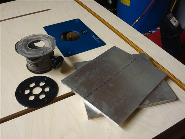
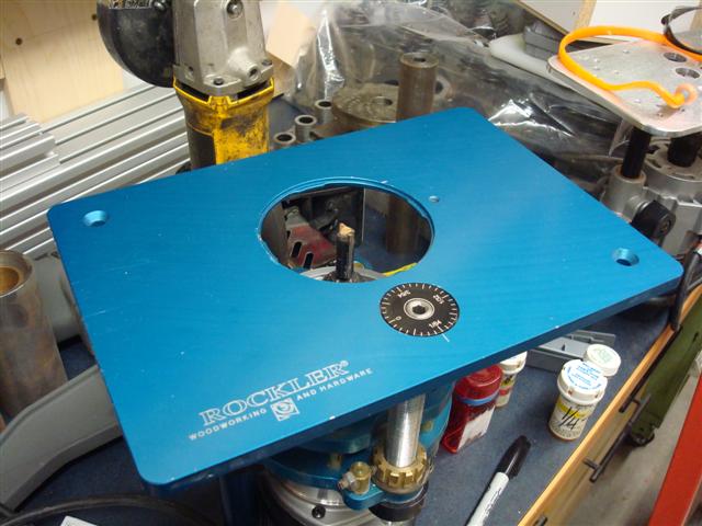
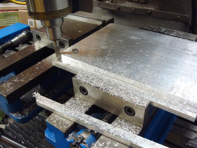
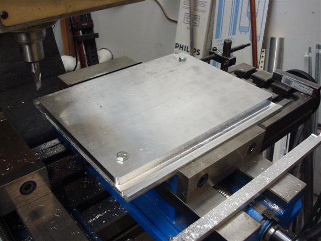
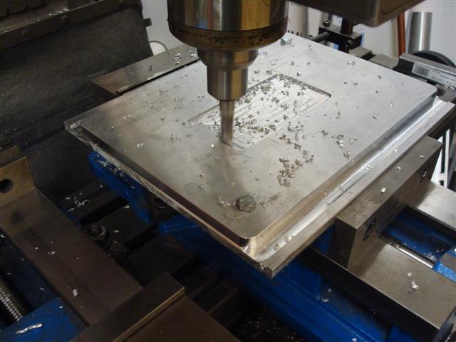
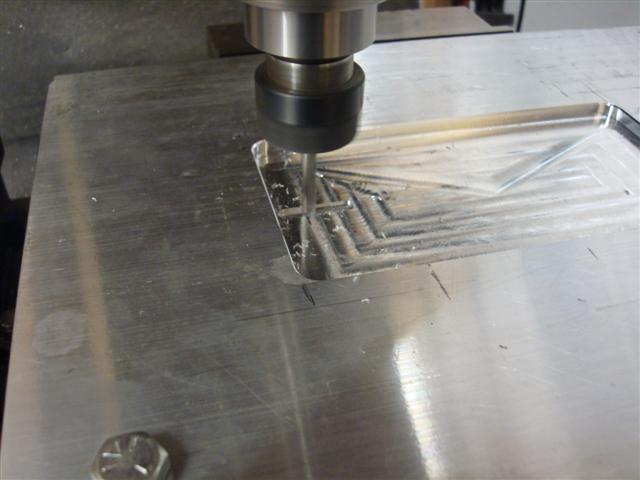
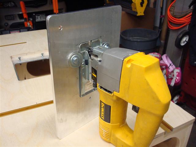
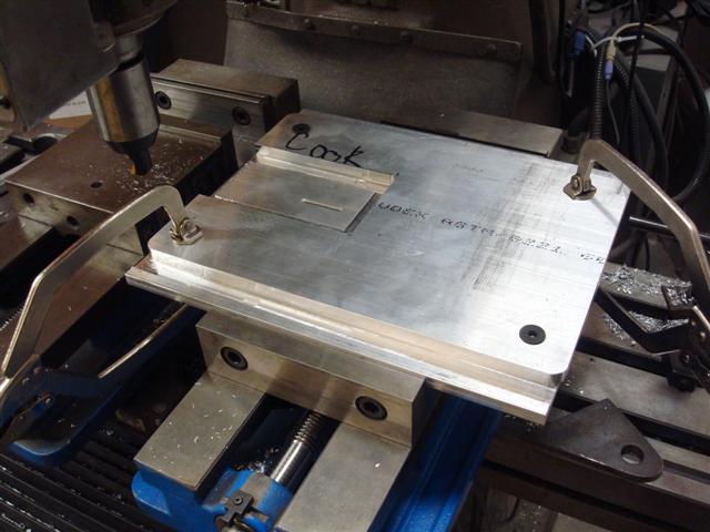
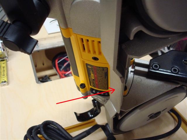
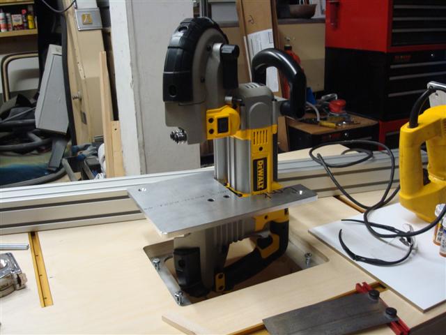
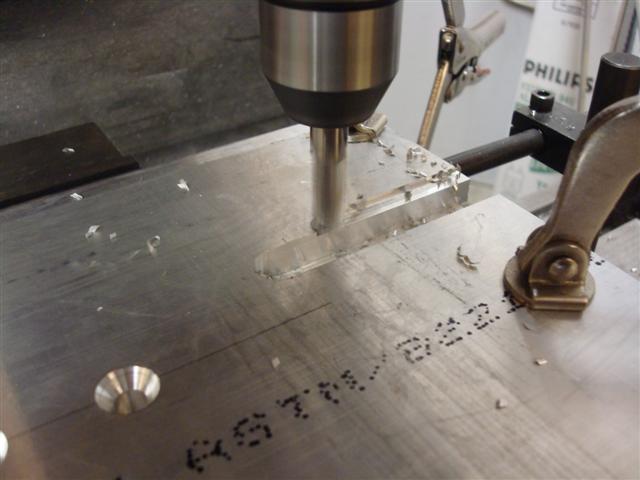
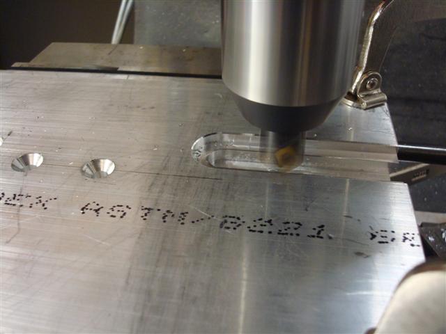
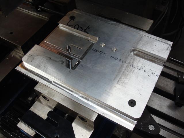
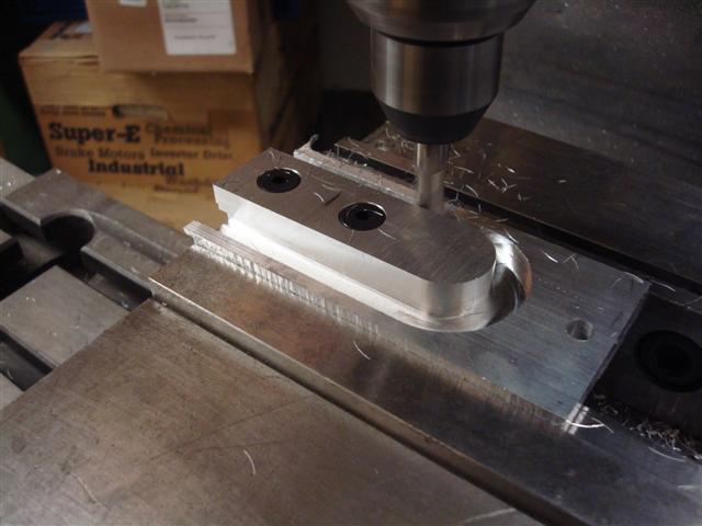
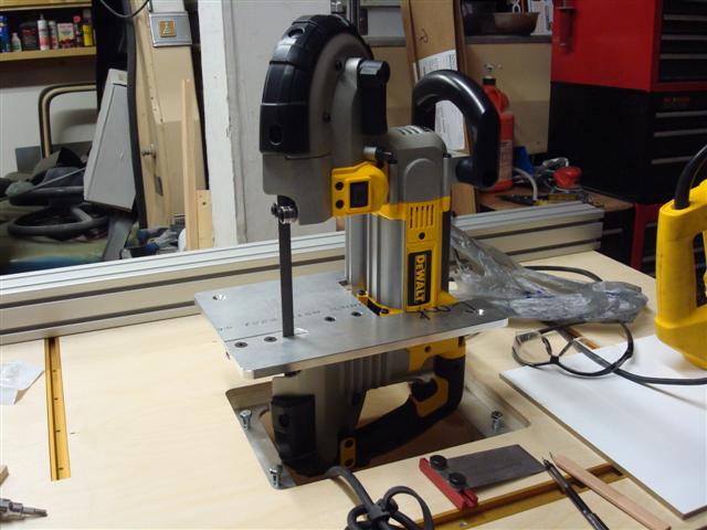
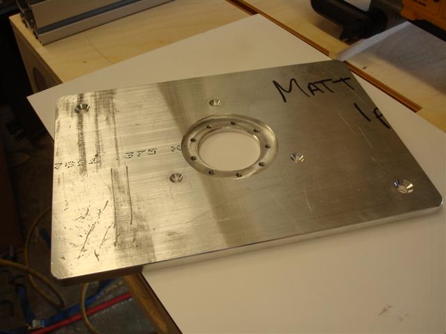
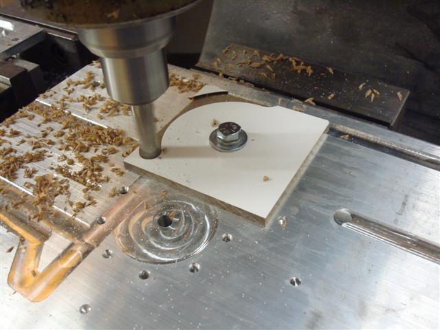
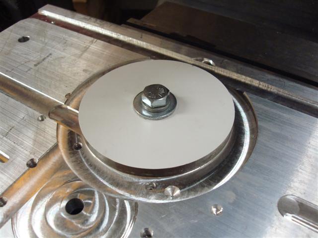
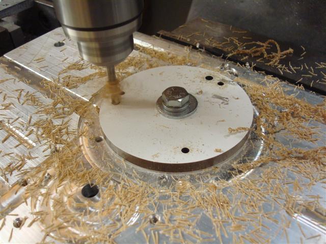
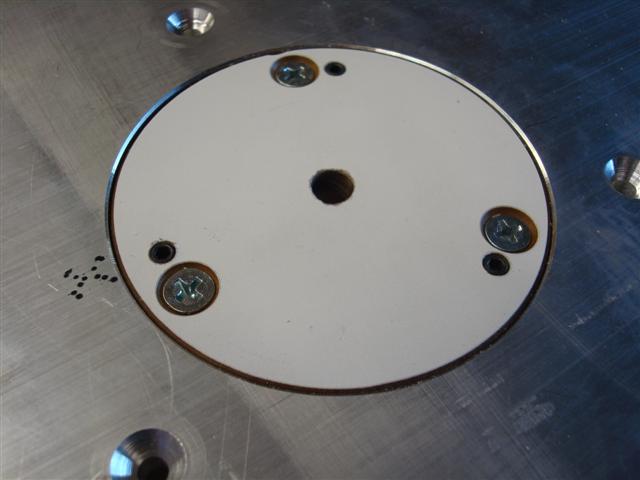
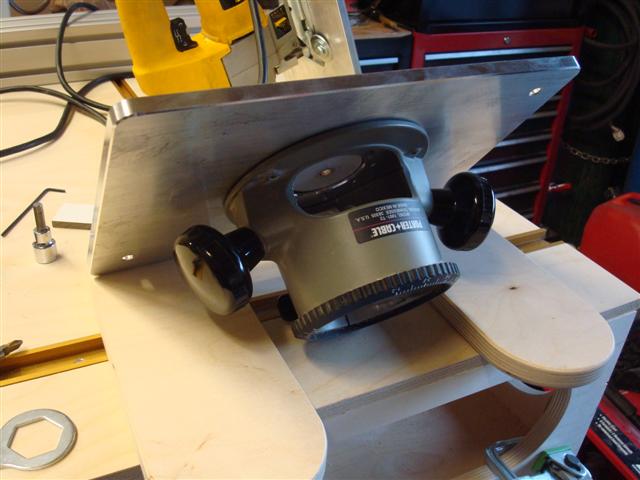
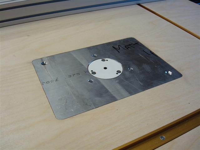
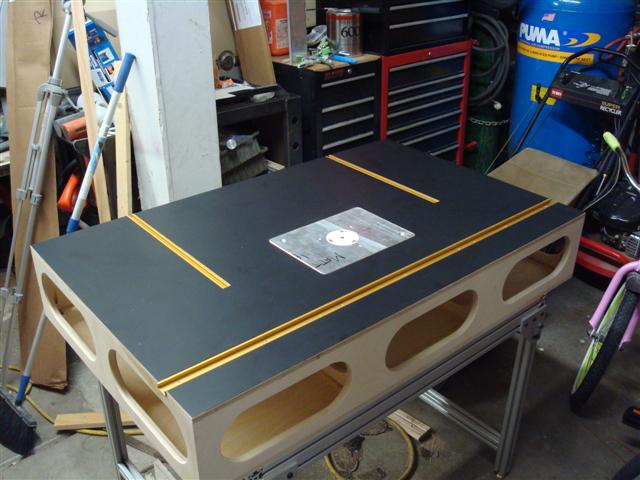
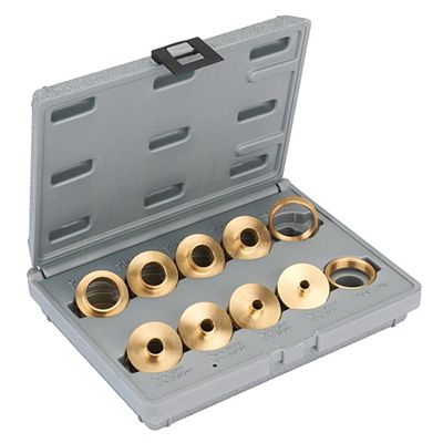
Moving along on the router table I need to cut some 1/2-inch wide slots for the aluminum extrusion that the fence will attach to. Since I had as many problems as I did attempting to use a guide bit to trace a template I decided to order a set of guide bushings and see if they're a little easier to use. After a few tests, I found that the primary difference between using a bushing and a template router bit was that the template only needed to be as thick as the guide bushing height which, for the most part, was my entire problem.

GuideBushingSet.jpg


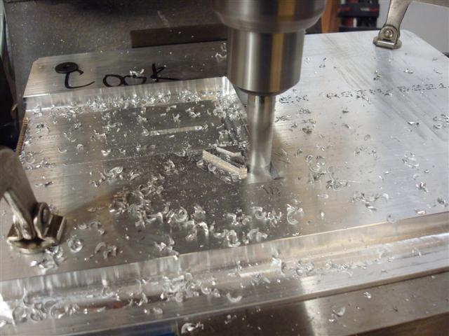
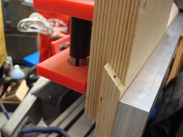
Now I need to cut some 1/2-inch wide slots for the aluminum extrusion that the fence will attach to using the guide bushings. One of the tricks I picked up while following Ron Paulk's video series on uTube was how he made fixtures to cut slots and I wanted to try to make one like his and try it out. Basically he uses four boards that have pocket holes drilled on one end. One fixture could make many different width slots.

RT30.JPG


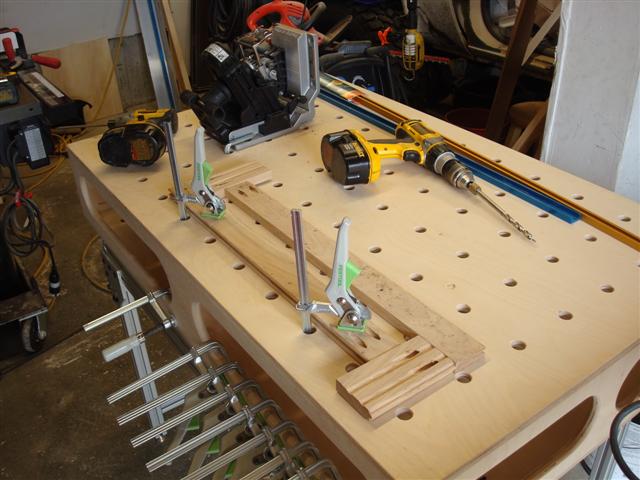
Though it seems simple (and maybe it should be), the wood I tried to use (left over hardwood) didn't screw together nicely using pocket screws and the pieces of wood ended up a little out of alignment which would result in a bad routing experience. Maybe what I should do is make one out of aluminum. I'll save that idea for a later time but to get it done I decided to fall back on the "how would I do it" approach.

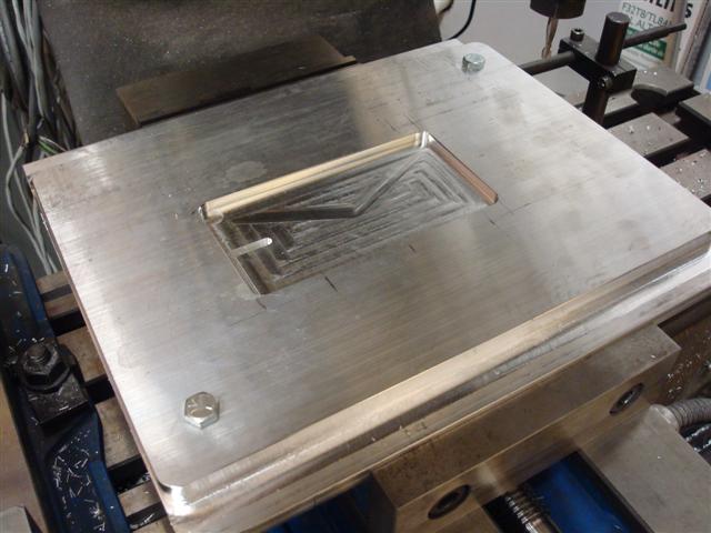
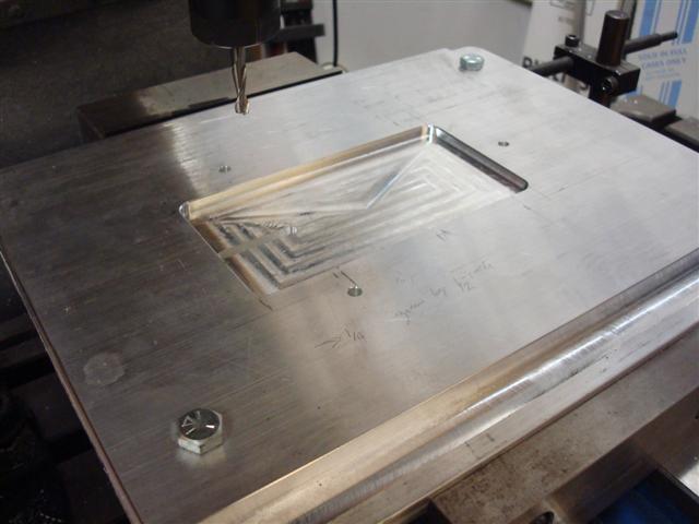
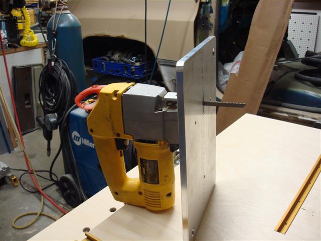
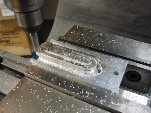
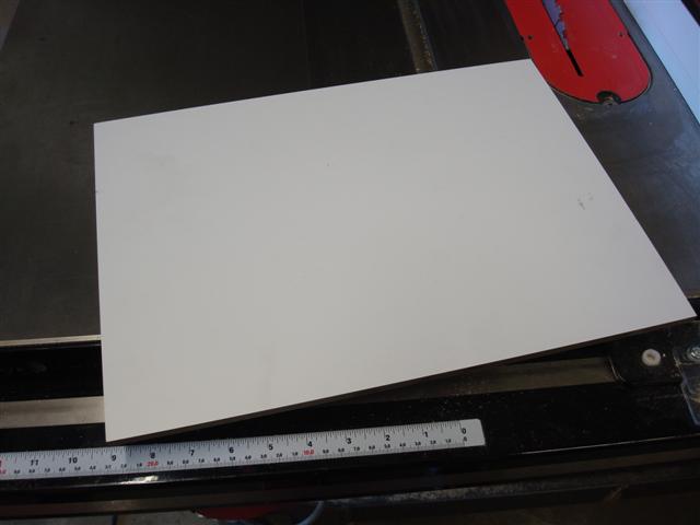
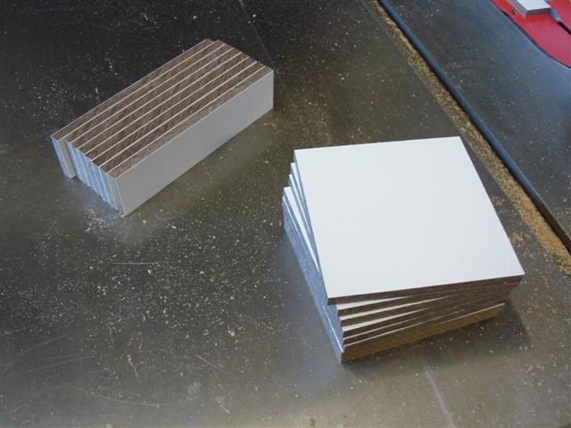
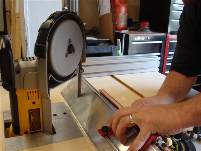
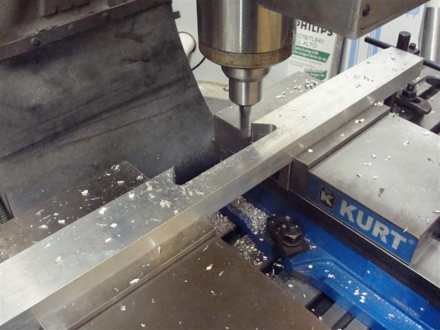
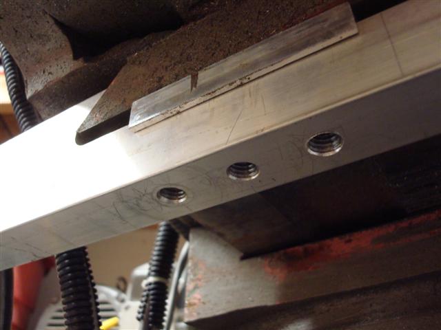
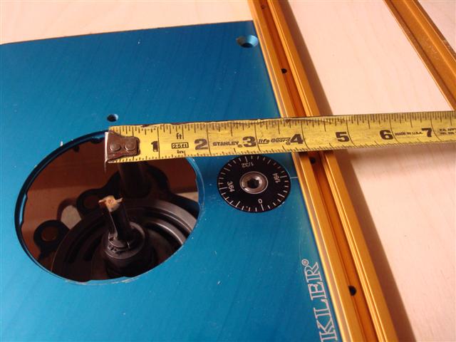
I cut two boards that were a couple inches longer than the slot and one of the boards to the desired inset width. I then trimmed a piece of wood that would result in the correct slot width based on the router guide (I was using a 5/8-inch wide one with a 1/2-inch bit) and then clamped the boards around it.

RT31.JPG


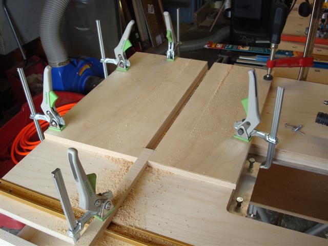
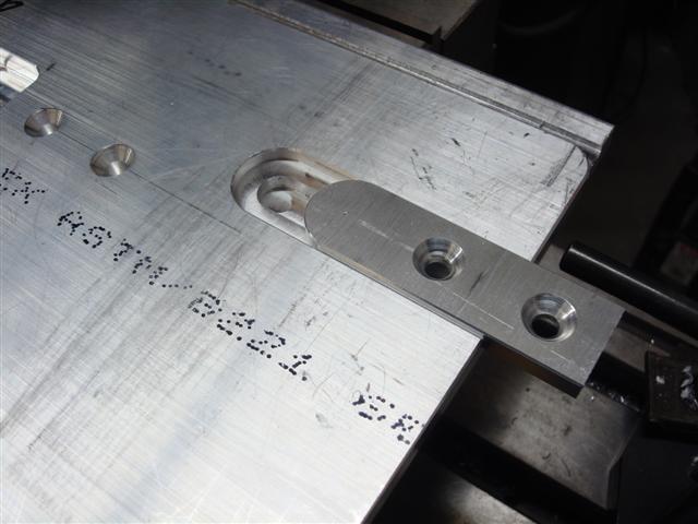
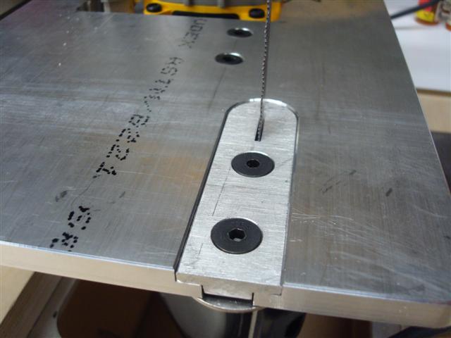
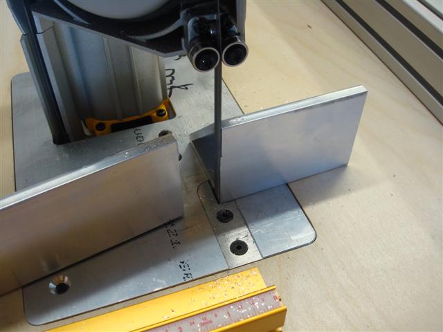
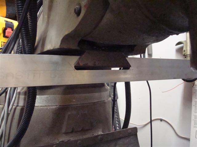
I used the jigsaw to square the corners and test fit the extrusion into the slots.

RT32.JPG


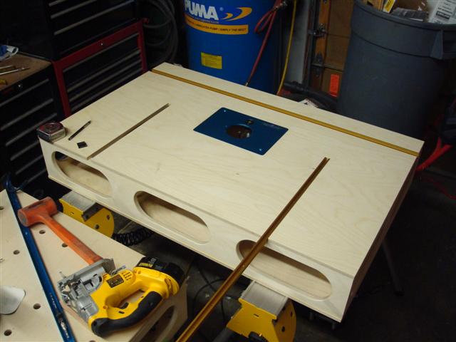
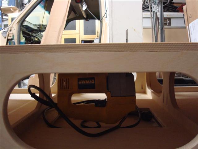
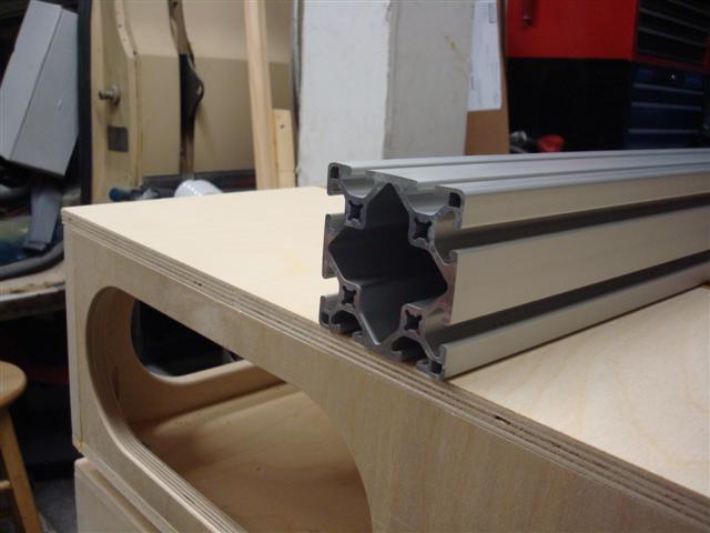
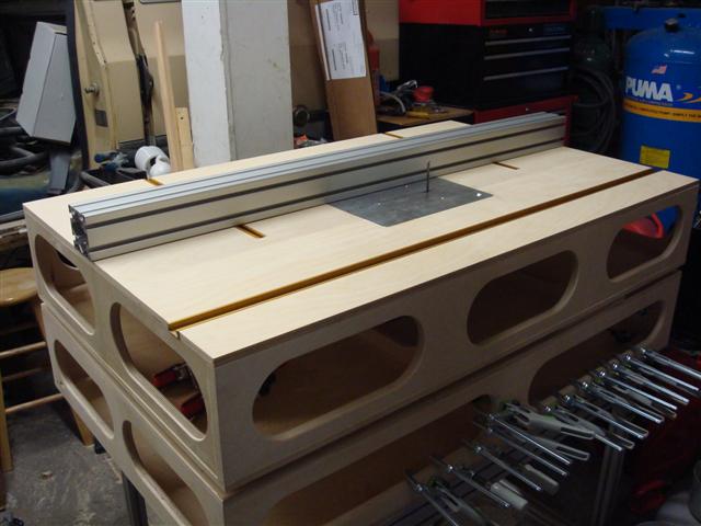
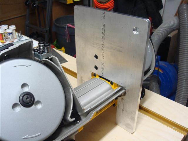
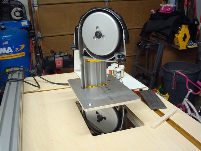
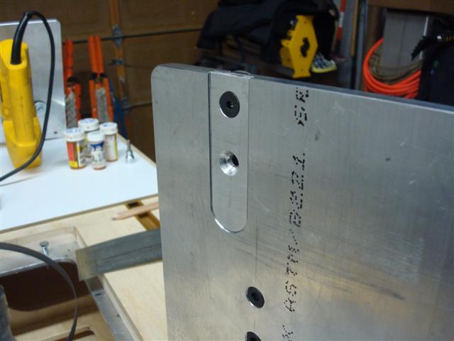
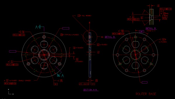
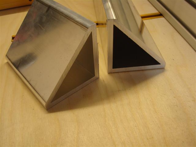
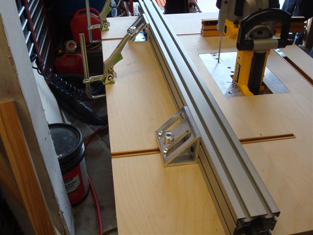
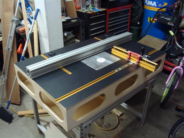
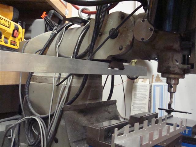
This perspective shows how much adjustment I'll have in the fence which should open up the options during fabrication.

RT33.JPG


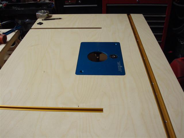
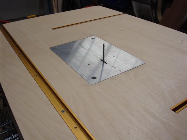
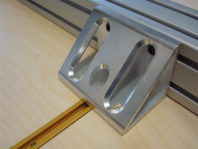
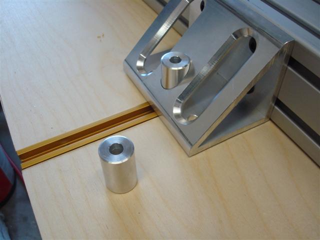
My plan is to use a 3 x 3-inch 80/20 extrusion for the fence. I really want a 3 x 6 but I've been unable to find an over-stock one on ebay. Either way, the fence will be 3-inches thick which will give me the ability to run a cutter width of up to 9-inches. Probably a bit over-kill since my biggest is maybe 3-inches. Not sure I'd want to cut with one much bigger or that I'd find a reason to.

RT34.JPG
 
To avoid these ads, REGISTER NOW!
OP
L

lilscorpion

Well-known member
Joined
Mar 15, 2010
Messages
3,599
Location
Colorado
such great work, I don't have nearly the same level of patience that you do

Thanks. I think it's persistence more than patience. On the weekends where I can't get into the garage for at least a couple hours I have a really hard time focusing in work the next week. I've learned that maybe my day job, though it challenges me and I do get to be creative, doesn't allow me to be creative in a way that satisfies me. I need the time almost more than I want the time.
 
OP
L

lilscorpion

Well-known member
Joined
Mar 15, 2010
Messages
3,599
Location
Colorado
I was able to locate some matte black laminate in town and spent a couple hours fetching it which I hate. Why on earth would a store a hour north be the only store in Denver that carries black? Some stores don't have any and others have white, three marble patterns, and no black. At least I didn't have to pay shipping. Before I stick the laminate I wanted to make sure the bottom cut-out is big enough so I don't have to risk screwing up the laminate if I have to cut it later. It will need be big enough to clear all of the power tools I intend on running in the table so I opted for working on the accessory plates today.

Even though I have a router lift, I really wanted to have the ability to have my other router setup as well in a plate so I could easily swap between setups. Doing so allows me to reduce setup time and doing so really saves the day big time if you ever have to go back to the previous cutter for some reason. Here's where dabbling in both metal and wood really pays off. I ordered a 4 x 1 foot piece of 3/8-inch 6061 to use for the accessory plates which was just enough to make three and the drop can be used as the machining fixture. Three plates in 1/4-inch online would cost more than $150 but I got the aluminum to my door for less than $60.

I used the miter saw to make the three cuts. I'll have enough for 3 plates and the drop, which is just short of long enough, will be perfect for the fixture.

RT35.JPG


After doing some research it turns out that router plates are not all the same (go figure). Rockler and BenchDog use the same 8 1/4 x 11 3/4 rectangle and the others (Kreg, Woodpeckers, etc) are all different. Some share, some are off by more than an inch. Having been a manufacturer I totally get why they do this. You can only use theirs if you use one of their router table tops. Smart but it really irritates me because it reduces the usability down the road (mostly by the guy who buys the table from me at some point). Here's the plate I need to copy.

RT36.JPG


With the 3 pieces ready to go, I took some measurements and got them into the computer. When I got to the point where I needed to know the corner radius, I spent fifteen or so minutes looking for my radius gauge with no luck so I fell back on my shop days and figured this trick was worth sharing. I pull a socket rail out of the toolbox and take it out to the item I need to measure. I flip through the sockets matching them to the corner radius and when I find a winner, I measure it. In this case the matching socket was 3/4-inches in diameter...divide by 2 and I'm looking at a 3/8-inch diameter radius.

RT38.JPG


I decided to copy the exact Rocker plate setup and use the large counter sunk holes to attach it to the fixture plate (as I'm sure the manufacturer did). After setting up, I drilled and counter sink the primary holes on all three plates.

RT37.JPG


Now I bolt one of the plates to the fixture and machine the outer profile to fit the hole in the table.

RT39.JPG


Now I'm ready to make mounts for the first power tool. I have some hardware headed my way and which shows first will likely help me make my decision.

JS4.JPG
 
Last edited:
OP
L

lilscorpion

Well-known member
Joined
Mar 15, 2010
Messages
3,599
Location
Colorado
Tired of waiting for parts - I decided to start with a jigsaw mounting plate. My jigsaw is one of the few tools that goes often unused in my shop. I really only use it when I'm unable to perform some op with any other tool. I believe, in part, my parents are mostly responsible for it because of a story they told me in my teems about an uncle that lost his thumb using one (though I'll bet money it was really a band saw).

I cut the profile .200 deep in the 3/8-inch plate to just a few thou over the length and width of the actual shoe size so the jigsaw would self align. Being perfectly accurate here won't matter because the jigsaw is far from a precision cutting tool.

JS5.JPG


A 3/16-inch wide slot was added for the blade to go through. I decided not to make it much longer than 1-inch even though that would prevent me from using some of the specialty blades.

JS6.JPG


Here's a better view of the final inner profile.

JS7.JPG


After test fitting the jigsaw I found that the slot needed to be 3/8-inch longer to the inside of the pocket so in the next op I enlarged the slot and machined the holes to be tapped for the retainer bolts. I'm tapping them to 1/4 x 20 so I need the ID of the hole to be .2010. I have the correct drill size but since the 3/16-inch end mill was already in the chuck, I just programmed the holes and let handle it for me.

JS8.JPG


All that's left for mill work is to flip the plate and break the edge. When you get in close and the light hits it just right you can usually get a fairly cool picture with an indexable insert. After seeing the pick I should have got inside and grabbed the big camera and attempt to get a pic of the insert actually cutting the chip.

JS9.JPG


I attached a pair of the Bessey Auto-Adjust clamps to the MFT and locked the plate down so I could tap the holes. Once tapped, I re-chamfered the tapped holes on both sides to clean up the entry and exit.

JS10.JPG


Finally I can attach the saw. I'll make some more secure hold-downs before I actually use it but I want to see it in the table so I just used a set of washers to lock it in. One on either side hold it very well so adding the third at the rear will prevent it from going anywhere for sure.

JS11.JPG


Kinda lucked out where I placed the jigsaw in the plate. When on end it's almost perfectly perpendicular to the table surface and very sturdy. Should make it easy to swap blades when necessary.

JS12.JPG


The router sits almost perfectly in the hole and hangs through the bottom one by only about a 1/4-inch.

JS13.JPG


And the finished view. As soon as I dropped it in I easily can see how useful it's going to be...and how easy it would be to whack a finger or thumb off.

JS14.JPG


What's kinda humorous is that as I'm typing this, I received the material I ordered to fabricate the fence for the table. I intentionally picked the 80/20 3030LS extrusion because of it's width so I could machine a cavity for the cutter and then attach dust collection to it on either end.

RT42.JPG


After mocking it up, I see I'll have to trim an inch or so off the end so that it's not longer than the table but, other than that, it should make for a really nice guide for material and plenty tall for most operations. Maybe down the road I'll be able to find the 3060 in the length I really wanted so I can have the extra height.

RT43.JPG


I already have an idea for how I'll attach it to the track but have to wait to do it this weekend when I have more time.
 
Last edited:
OP
L

lilscorpion

Well-known member
Joined
Mar 15, 2010
Messages
3,599
Location
Colorado
Moving along on my (self proclaimed) ultimate multi-function table I started working on the second power tool mounting plate - a portable band saw. Shortly after the router table structure was built, an idea presented itself that I had trouble shaking for a couple of weeks. I've been wanting a portable band saw and a table for a while and, after a friend gave me some measurements, I realized that a particular version of the Dewalt saw would fit in my cutout for the router plate. Research indicated that the portable band saw wouldn't be great for woodwork but would be very useful in metal and aluminum projects which I tend to have a lot of.

After sourcing the saw itself (and waiting for almost a week and a half for it to arrive) I took some measurements and found that I needed a slot that was approximately 4 1/4 x 3 1/2 for the plate to clear what I'll call the neck of the saw.

BSP1.JPG


Originally I thought the saw would but all the way up against the edge of the cutout (in the table) but, after taking a few more measurements I realized that I actually needed it to set in about an inch so I expanded the rectangle to 5 1/8-inches in width and cut the slot.

BSP2.JPG


With the basic profile cut I'm glad I decided to use 3/8-inch thick material for the plates. Originally I was going to use 1/4-inch because of the cost difference but now I realize that the 1/4 likely wouldn't have had enough rigidity to support the saw with such a large profile cut out of one edge.

BSP3.JPG


Back to the saw I have to make a few measurements on the casting on the back side of the saw so I can cut an allowance for it. The casting in this spot serves as a blade guard.

BSP4.JPG


I over sized the profile a little and cut it into the plate.

BSP5.JPG


Next step is to drill the mounting pattern. The factory guide is mounted to the saw using two counter sunk bolts that sit just behind the blade and will be all that will attach the saw to the plate.

BSP6.JPG


After drilling two 1/4-inch holes and countersinking them to the correct depth, I was able to mount the saw to the plate.

BSP7.JPG


After taking some measurements I found that I'd have more than a couple degrees of adjustment in the table so squaring up the blade won't be a problem each time it's mounted.

BSP8.JPG


BSP9.JPG
 
OP
L

lilscorpion

Well-known member
Joined
Mar 15, 2010
Messages
3,599
Location
Colorado
Now I need to machine a slot for the blade. Finding the exact location will be easy because the rollers on the bottom are nearly touching the plate. I want the insert to be replaceable because it will have rough edges rubbing it frequently.

BSP10.JPG


I measured the center of the bearings and then machined a slot that allows for enough clearance on either side of the blade.

BSP11.JPG


With the table only 3/8 of an inch thick, I machined a second slot only .200 deep to act as a shelf for the insert to sit on. This will allow it to lock into place and gives me a way to make it sit level. The goal is to make the insert about 3/16-inch thick and then put tiny set screws in it so I can level it as needed though I'll wait and see if it's necessary. Having the insert sitting 10 thou lower than the surface of the table may not matter at all.

BSP12.JPG


The main part of the band saw mounting plate is now done.

BSP13.JPG


Since I haven't made an insert yet I decided to make the first one out of aluminum since it's easy and fast to machine. I used a piece of 1/4-inch 6061 that was left over from a previous project, drilled, and countersunk the holes to mount it to a fixture. I then used the large cutout drop (from the band saw plate) for the fixture and drilled the corresponding holes into it to match and cut the profile.

BSP14.JPG


With the profile cut I remove it from the fixture and check to see how it fits. The first fit was close and I removed about .010 more to allow it to slide in easily. Now it's smooth like butter.

BSP15.JPG


Right now it's about .040 taller than the plate and I need to relieve cut the back so it will sit flush (or slightly below). Since stuff tends to get into grooves and cracks I decided to cut a little extra and use some set screws to level the plate instead of attempting to cut it perfectly flush. This will allow me to drop it a time or two and yet still be able to use it.

BSP16.JPG


I plan to make a retention plate for the backside but until then a fender washer works perfectly for mock-up. It looks like the bolt holes will be a little closer to the blade than I'd really like but, in this picture, the table is actually slid all the way back (there's about 1/4-inch adjustment). On the next insert i'll move the holes forward another 1/8-inch.

BSP17.JPG


And a finished picture of the insert installed in the table. Next step is to cut the slot for the blade with a slitting saw.

BSP18.JPG


The relief cut turned out to be much easier than I thought. Originally I was planning to use a slitting saw to cut the notch for the blade but just before I put the saw into the mill I realized that I could use the slot as the guide and cut the groove using the blade and it took maybe 10 seconds to do so.

BSP19.JPG


Now I'd lucked into using the saw for the first time (it ate the aluminum) and I got to see the table fully assembled. Since I cut with the saw laying on it's back I also had the opportunity to see how the dust/shavings shed off of the saw blade and realized that the dust collection is going to work awesome since all shavings should pass through the blade relieve into the cavity where the vacuum will be.

BSP20.JPG
 

sloppy

Well-known member
Joined
Mar 3, 2013
Messages
481
Location
Ohio
So on the jig saw deal are you gonna make a over arm or something to keep down pressure on the work??? I have never seen any scroll saw/jig saw type of tool used like that with out some type of arm..
 

Coolabah

Well-known member
Joined
Jun 6, 2010
Messages
1,359
Location
2nd Floor, 3rd on the Right,Narooma, Australia
I spend my share of time with the kids and wife. I'm also an addict. I have to be building something. I'm a software engineer by trade but that job is just mental gymnastics. I gotta do something physical or I go crazy. I jump back and forth between wood and metal and throughout the years, I've managed to learn a little here and there from friends or jobs I held at one time or another. So the way I keep from going mad is to build stuff. I have maybe a dozen projects going at any one time. Sometimes I work on the house (makes the wife happy), sometimes I work on the truck I'm building (when I need some greasy clothes), and other times I work on the shop and try to figure out ways to make working in it easier, faster, etc.. But to be fair, I only get a day here or there. It just so happens I'm burning some built up vacation. Life is busy and normally I have to steal a couple hours here or there...or I can't sleep at night.
Wow I picked you for a fitter/turner/machinist ( whatever its called in your part of the world !)
I am impressed , envious, and intimidated all within one breath :bowdown:

... thanks for the inspiration !! :rocker:
 
OP
L

lilscorpion

Well-known member
Joined
Mar 15, 2010
Messages
3,599
Location
Colorado
Thanks guys, I appreciate the compliments. I'm really diggin' how the band saw plate turned out and seeing it come together gave me another idea which is what keeps me going.


So on the jig saw deal are you gonna make a over arm or something to keep down pressure on the work??? I have never seen any scroll saw/jig saw type of tool used like that with out some type of arm..

I haven't cut much with it yet so I'm not sure what problems I'll have. In thinking about it I'll probably use blades that cut on the up stroke (inverted it will cut toward the table surface) to help minimize the pushing of the material away from the surface but I'll also be making a sled of some type to clamp the item I'm cutting to. I'll probably not do much scroll type cutting and use it more for when I need to make an internal cut.
 
Last edited:
OP
L

lilscorpion

Well-known member
Joined
Mar 15, 2010
Messages
3,599
Location
Colorado
As I'm sure I've mentioned before I tend to get side-tracked weeks by a secondary or tertiary project that struck me as cool in the middle of another project. This router table is no different. Instead of finishing the table itself I'm off in lala land making router table plates for every tool I can think of and I HAVE TO finish them before I can get back on the router table itself. When I first figured out I was doing it I got stressed out but I've learned to go with it.

Today I knocked out the porter cable base router plate since it's the last one I'd planned to make. In the past couple months I know I cut the pattern for the base but I couldn't find the drawing so I had to look it up again. Glad I did because I found a couple cad files for router plates that I'd like to make in the future like this one that also has enough of the information I need to stop me from looking further. If you're interested in the cad file, I've made it available here. It's everything you'd need to make an exact duplicate of the one that came with the router.

609dxf.jpg


The router plate for the lift has a fancy locking ring that allows zero or minimal clearance around the cutter. I want to do something similar but less complicated for this plate. I wouldn't mind making it exactly the same except I don't want to spend the time messing with practice pieces so I opt for a less complicated design that uses flat head counter sink screws to retain the plate.

RTP14.JPG


I don't need much of a shelf but decided that I'd rather have a bigger one so the plate would have a little more flexibility down the road (meaning it's easier to remove more later if needed). The cutter ID is cut to 2 1/8-inches which is plenty big for the cutters I'd run on this 1 3/4 horse router. For the bigger cutters it would make more sense to run them on the bigger router anyway. The shelf width is 3 1/4.

RTP15.JPG


And a shot of the holes after the edges are broken with the chamfer bit.

RTP16.JPG


Next I drilled the mounting pattern for the router base.

RTP17.JPG


The inserts will need threaded holes for the hold down screws. I decided to go with the same thread pitch as the screws that the router uses (since I have quite a few) and drilled 3 sets of 3 so I could have extra sets in case one of them strips at some point. Here's a shot of me tapping. My CNC conversion has the option for rigid tapping but I didn't get it so I have to disconnect the Z/quill and **** the tap into the material and reverse the motor to pull it back out. Works great but is a mild pain (meaning I try not to do it unless I have to).

RTP18.JPG


RTP19.JPG
 
Last edited:
OP
L

lilscorpion

Well-known member
Joined
Mar 15, 2010
Messages
3,599
Location
Colorado
I'm using 1/4-inch thick phenolic sheet for the inserts because it's extremely stable, easy to machine, and taps easily like aluminum (according to what I've read). I ordered this sheet from Amazon and was disappointed when "colors vary" ended up being white.

RTP20.JPG


Since I also have some inserts to make for the band saw table I decided to cut nearly the same amount of both on the table saw so I could run a batch and have plenty later.

RTP21.JPG


When I cut material for the first time I usually take a conservative pass since I don't know what it will do. Turns out I could have hammered through it but light passes still work and are safe.

RTP22.JPG


RTP23.JPG


Next I drilled 6 holes - three for the hold down screws and three for the set screws.

RTP24.JPG


And after countersinking three of them, breaking the edge, and tapping three of the holes, I was able to drop it in the plate and level the insert.

RTP25.JPG


And attached the base with a few screws. Out of dumb luck I followed the instructions in the cad file to a T and found out why the screw pattern started at 30-degrees. Turns out that was necessary to get the handles to align with the plate and Had I not done the rotation I would have found out that the base didn't fit inside my table without taking off the handles.

RTP26.JPG


RTP27.JPG
 
Last edited:
OP
L

lilscorpion

Well-known member
Joined
Mar 15, 2010
Messages
3,599
Location
Colorado
Got back out there today and modified the table to accept the band saw and decided to try it out. I have a full size horizontal so my expectations were't set too high but I was impressed and I'm probably going to use it much more than I had thought.

BSP21.JPG


It had no problem cutting through a 1/4-inch wall piece of 3 x 3 8081 gusset though it did take a little patience to get through the vertical which was basically a 3-inch tall piece of aluminum.

BSP22.JPG


Not bad for a little band saw. I scribed a line so I could measure the deviation during the cut and the blade didn't track perfectly and was out of square by just under a 32nd by the end of the cut but some of that could be eliminated by using a sled.

BSP23.JPG
 

PT Doc

Well-known member
Joined
Nov 12, 2010
Messages
3,197
Why did you decide to have the slit for the Portaband at the front and not from the machine side?
 
OP
L

lilscorpion

Well-known member
Joined
Mar 15, 2010
Messages
3,599
Location
Colorado
Why did you decide to have the slit for the Portaband at the front and not from the machine side?

The DOC is just over 5 inches and the relief to make the saw fit inside the plate was 4. Had I made the slit from the rear I would have had to make a slit just longer than 9-inches to make it work and the width of the plate is 11 3/4-inches. Though it's likely the 3/8-inch plate could handle supporting the saw with a cut over 3/4's the length of the plate it seemed like it was a better idea to make the relief cut from the front to avoid the hopefully not. When I first put the saw in I dreaded having to pull the blade to mount it but the blade comes out so easily that It doesn't bother me at all...in hind sight it seemed like a silly thing to design around.
 
To avoid these ads, REGISTER NOW!

akdiesel

Well-known member
Joined
Aug 8, 2008
Messages
2,617
Location
Wasilla, AK
lilscorpion

Great fabrications.
Building the tools to make the projects is just as fun and gratifying as making the projects.
 

mikeburris

Well-known member
Joined
Aug 4, 2012
Messages
188
I decided to make a holder for my extensions...


View attachment 340702

I wonder if someone has seen something along these lines. I would like to find holders that fit a little better. Once I get it like I want I plan to paint the board and clean it up some.
 
OP
L

lilscorpion

Well-known member
Joined
Mar 15, 2010
Messages
3,599
Location
Colorado
Your name was brought up today on the CO4x4 site regarding resplining axleshafts.

Been a long time and don't presently have an indexing head that would fit an axle shaft (or a fixture that accomplishes the same thing). Maybe if the need presents itself...lol, I mentioned it and the wife gave me "the look". Guess I don't need any more of anyone else's projects.
 
OP
L

lilscorpion

Well-known member
Joined
Mar 15, 2010
Messages
3,599
Location
Colorado
Didn't get too much time in the garage this weekend but I managed to get the brackets made for the fence. I used 80/20 gusset material I had ordered for the frame.

RT44.JPG


To attach to the track a t-bolts will go through bushings that are a snug fit into the machined hole in the bracket. I used some 7/8-inch 6061 I had laying around.

RT45.JPG


Given the t-slots in the extrusion, I can now adjust them anywhere and move the extrusion around as needed. They turned out a bit more high-tech in appearance than I visualized but it's a neat touch.

RT46.JPG


While I was doing a few other things around the shop I ran a Jacob's chuck tray program I designed a little while ago. The tray is needed so I can move the chucks from my tooling cabinet into a drawer in the lista so I can make room for some of my other R8 stuff. I shot a vid of it so you guys could check out the CNC in action. The entire profile for all of the chucks were made by programming XY and XZ arcs in various sizes. The end mill is a 3/8-inch ball with a .025-inch overlap to make the profiles look smooth.

<iframe width="560" height="315" src="//www.youtube.com/embed/MtlM6AQsg2E" frameborder="0" allowfullscreen></iframe>
 
OP
L

lilscorpion

Well-known member
Joined
Mar 15, 2010
Messages
3,599
Location
Colorado
I was fairly lucky this weekend. It's a long weekend, the first weekend since lacrosse season ended (so no games), and I took a couple of extra days to make it even longer. Perfect to get some things done. I'm sure you're all getting a little tired of the router table build because I am. Yesterday I managed to get the lid glued on and let it sit over night.

RT47.JPG


With the glue dry, I was ready to apply the laminate. After applying the adhesive I managed to mis-stick the laminate 1/8-inch offset in a bad way. I used a small putty knife and patiently pulled the laminate back off which was really painful. Once I had it all off I fought getting the glue off (or just enough so it would level again). I was attempting to maintain my cool throughout the entire ordeal so I couldn't bring myself to snap a picture of the mess though in hind-sight I probably should have anyway. It was an interesting sight - my hands were ****** from getting nicked a dozen times by the laminate I was attempting to get off and I'm sure my face was red. After fighting my way through it and taking a night to sleep the pain off, I was able to give it another go the next morning. Fortunately the second attempt executed perfectly. I was done in less than 20 minutes from opening the can of adhesive to routing around the table.

RT52.JPG


A final shot with the fence and the miter sled. I plan to make a few accessories for it but the table will go "into service" tomorrow when I need to narrow some hardwood floor planks and re-cut the tongue and groove in them. After more than a month, I'm ready to move on.

RT53.JPG
 
OP
L

lilscorpion

Well-known member
Joined
Mar 15, 2010
Messages
3,599
Location
Colorado
Thank for the props...always learning to expand my skills, sometimes the hard way.

Figured I'd share this as well. While I was cooling off from the laminate fiasco I worked on the accessory bar for my knee mill. A year or so ago I found this hobby machinist's website where the guy made an accessory arm for his knee mill and attached it to taper on the ram. It was a cool idea and he made a couple of different attachments for it. I've been thinking about making my own for some time now and today I decided to knock it out as a means to clear my head. Not having the correct cutter I figured out that I could program the taper on it's side. As I've said in the past, CNC can be justified when you realize you won't need nearly as much specialty tooling. I measured and the angle was exactly 50-degrees so I programmed it out and got started.

MA1.JPG


With only a single adjustment, the taper fit perfectly.

MA2.JPG


On the end I want to have a R8 tooling rack and I'd like to move the existing light I have onto the arm and add a second light on the other side. I also have this cool accessory arm I'd like to attach as well but I'm planning on having provisions on both sides for it so I'm not limited in where it mounts. The material I had laying around is 1 x 2-inch 6061 and it's a lot heavier than it needs to be even to hold all of this stuff so I need to lighten it up a bit.

MA3.JPG


To keep the arm in place I drilled and tapped three 3/8-inch x 16 set screws 1 inch apart to lock the arm into place. The little piece of aluminum angle is just a friction plate so that the set screws don't chew up the paint (not that it would really matter or make it look worse).

MA4.JPG


Then I drilled and tapped two more holes 10-inches apart to attach a piece of plywood that has a 45 degree bevel cut into it - aka french cleat. I counter sunk the two holes so that the bolts would be clear of the tooling mounts. The neat thing about the french cleats is that they really do stay in place and they really don't want to move when there's weight on them.

MA6.JPG


The total length of the french cleat is 18-inches which just happens to hold exactly two of the tooling holders that I have in my cabinet. Since it's a ways ago (in this thread) this is the tooling cabinet I'm referring to. There's 4 nine inch long tooling racks on both sides of this slide-out (uses four of the 100lb. full length slides to handle the weight).

9udujuqa.jpg


Most of the parts I make use at most 4 tools so this new setup should allow me to grow a little.

MA7.JPG
 

gearhead1

Well-known member
Joined
Oct 14, 2013
Messages
1,935
Location
NC
Nice work! I wanted to make the socket holders and have been looking for a place to get HDPE sheet for a while. I don't work much with wood (something I want to do more of), so I wouldn't ordinarily go to a Woodcraft. I saw you got it there and did a Google search and there's a Woodcraft close to me. This is Awesome! I have a Bridgeport and there's going to be some plastic chips flying!
 
Joined
May 17, 2014
Messages
12
I don't have my personal tools and I usually borrow them from my dad......he is very finicky about them so he often keeps them out of everyone's reach unless you plead him for it that you really need them.
 
OP
L

lilscorpion

Well-known member
Joined
Mar 15, 2010
Messages
3,599
Location
Colorado
Re: Tool Organization

Had to drop the bandsaw into the table today and make a few cuts so I thought I'd snap a shot of the finished look and share.

http://www.3amcook.com/Images/Woodworking/RT50.JPG

The portable bandsaw, from what I've read, isn't good at cutting wood. My experience is that it's blade speed isn't fast but it cuts wood just fine. I free handed a few cuts along a line and it worked very well. Not fast but I don't need it to cut fast.
 
To avoid these ads, REGISTER NOW!
Top Bottom