To avoid these ads, REGISTER NOW!

Tooling organization

OP
L

lilscorpion

Well-known member
Joined
Mar 15, 2010
Messages
3,599
Location
Colorado
Re: Tool Organization

Update on the MFT - I'm not enjoying the plywood surface. though it's cheap and maintaining it's flatness (thus far), it's far too porous for the general use. Mildly dirty hands? Dirty table and the only way to get it to look "clean" again is to sand it. With a laminate rem perfectly sized for the table sitting in the corner I caved and stuck it today and I'm very pleased that I did. Shortly after I used the table for a glue-up and the little drops came up without effort. Even dry glue comes up easily with a razor blade. Can't do that with plywood. Looks much cooler too.


MFT6.JPG
 
To avoid these ads, REGISTER NOW!
OP
L

lilscorpion

Well-known member
Joined
Mar 15, 2010
Messages
3,599
Location
Colorado
Hmm, I have an mft and spare laminate sitting around doing nothing...


Now ya got me thinking...for the festool tops it would make total sense to laminate one side for things like assembly and general use and use the other side for sacrificial duties. That would be handy.
 
OP
L

lilscorpion

Well-known member
Joined
Mar 15, 2010
Messages
3,599
Location
Colorado
After about 2 years I've decided to work towards completing the cabinets. All I have left is 4 counter tops and some little touch up stuff but I decided this last weekend that it's time to wrap it up.

Counter top 1 is the smaller drawer assembly that hangs above my saw. It's just over 3 feet long and maybe 15 inches wide at best. I really want to keep the plywood theme so I use a sheet of the baltic birch, cut it to size, and build it up with scraps and left-overs from previous projects.

DG1.JPG


the build-ups, other than the long one, are completely made from screw-ups from making doors a year back. I almost always use or re-use everything and attempt to let nothing to into the trash except dust.

DG2.JPG


Adhesive is applied and dowels setup to aid in the placement of the laminate.

DG3.JPG


The only exposed corner is given a soft 2 1/4-inch radius.

DG5.JPG


And a couple of coats of poly is applied to give it the amber look of the rest of the assembly.

DG6.JPG


Since it turned out just as I had hoped I went ahead and placed the order for the remaining sheets of laminate. I'm getting close now...
 
Last edited:

CudaDude

Member
Joined
Oct 11, 2013
Messages
15
Location
WC,TX
With the skills you have and the extent you've gone to as far as organization, I was wondering if you have some type of dust collection for the woodwork. If so, I'd imagine it would be nothing short of miraculous, would you post some pics.
 

benjammn

Well-known member
Joined
Apr 27, 2013
Messages
52
Location
Chandler, AZ
I can't agree more with everyone here, you have done a masterful job on all your work, please accept this as my nod to you at this level of your quality and form, you have my utmost respect
 
OP
L

lilscorpion

Well-known member
Joined
Mar 15, 2010
Messages
3,599
Location
Colorado
If you've been reading along you've seen that I made quite a few tool mounts for the router cutout in my router table. While working on a project recently I found myself switching tools in the table half a dozen times in a row to accomplish something and at that moment I realized that I needed a way to use many of the tools at once. What I also realized is that in many cases, I didn't need the full size of the MFT table to perform the op so smaller versions would work fairly well and be much easier to store - and here's the idea I had while building my full size router table - Router Buds. I started by cutting two small tops that were just big enough for the power tool and a little room for a miter gauge.

RB20.JPG


With pocket screws being a fast and strong way to assemble the frame, I cut them into the front and the back.

RB21.JPG


Assembly started and I took full advantage of the MFT by clamping through it from the bottom so I could ensure everything was exactly where I wanted it to be. Even though I've been using it for a while, I still am impressed how useful it is.

RB22.JPG


After the glue dried I cut a slot for the miter track with the router.

RB23.JPG


Adhesive was applied to the sheet and the top of the table so the laminate could be applied.

RB24.JPG


Once the laminate is rolled out a flush cut bit is used to trim the laminate to the edge.

RB25.JPG


The band saw is used to cut down the miter track to the correct length..

RB26.JPG


Holes are drilled (added) to the miter track. The previous screw pattern only had two that would line up with the smaller table top.

RB27.JPG


Apparently the fit was a little tighter than I usually make them. I had to tap it in with a drift to get it to seat correctly in the groove.

RB28.JPG


The same steps are followed and the second table is assembled. This orientation is 90-degrees when compared to the first.

RB3.JPG


A slat wall was added to the space that can't be used under the lift.

SW1.JPG


The Router Buds will be used primarily on the slat wall I just added on the wall above the table saw and moved up and stored on the same wall while they're not in use. Out of dumb luck this one, when hung at the same level as the drawer cabinet works well as a counter extension as well (though not intended).

RB30.JPG


And the pair of "Router Buds"

RB29.JPG
 
Last edited:
OP
L

lilscorpion

Well-known member
Joined
Mar 15, 2010
Messages
3,599
Location
Colorado
MFT Horses?

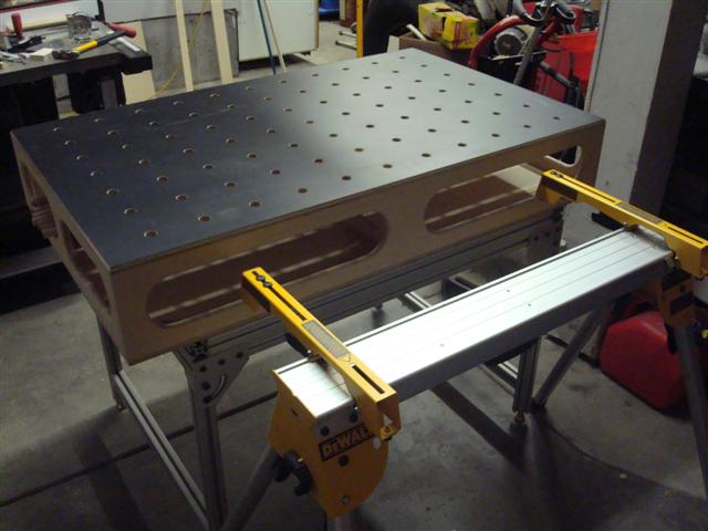
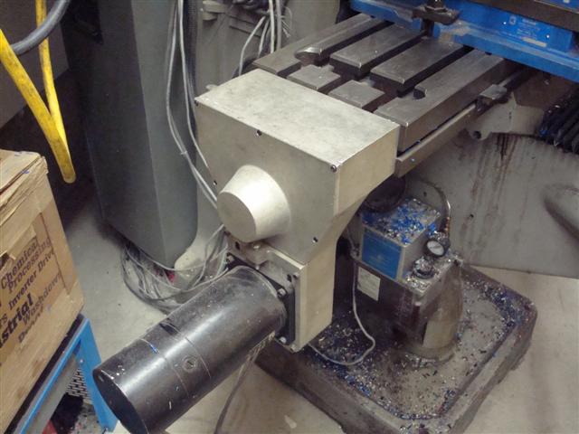
Since I have a long weekend for the 4th I figured I'd spend a little time cleaning up around the shop and trying to get everything back into it's home. I haven't gotten very far because I got side-tracked again. I was moving things around when I found myself moving the extrusions I have for the large MFT frame I still haven't put together yet. I moved them not once but 3 times and the third I was no longer amused. I decided I'd put the frame together because assembled it would be easier to move than in pieces. It was the next two events that cost me the day. I first realized I didn't have a surface big enough to assemble the frame. I got out my Dewalt saw horses and found that they would have worked nicely had their width been about 8 inches longer. When I set up the horse I thought "sure would be nice if they were the same height and width as the MFT".

MMFT1.JPG


I recalled that I had ordered extra sets of the miter saw stands that attach to the saw horse so I pulled a pair out and attached them to the horse. I was half hoping that the height difference would be close enough to the MFT that I wouldn't need much of a spacer but I knew I wouldn't be that lucky.

MMFT2.JPG


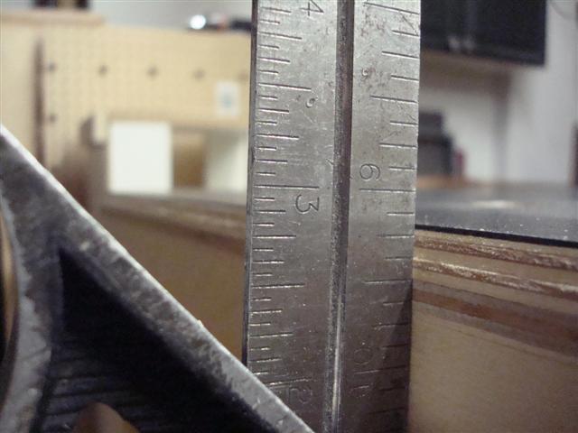
Sure enough the difference was just under 3-inches. Almost perfect for a 2x4 on end. At first I was thinking I could screw a couple of 2x4's to a piece of plywood and match the height nearly perfectly (and if it wasn't a slight trim on the 2x would certainly get me there).

MMFT3.JPG


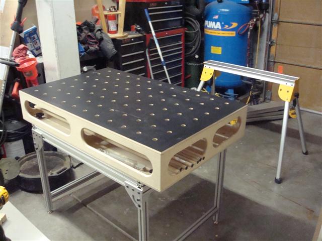
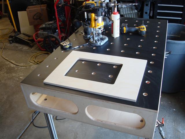
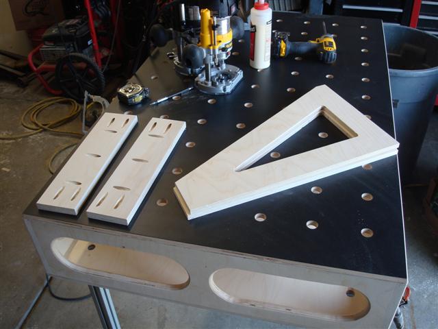
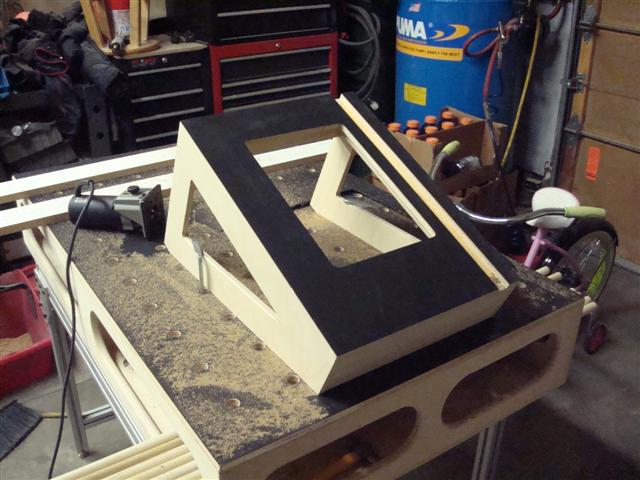
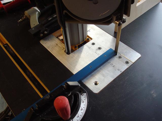
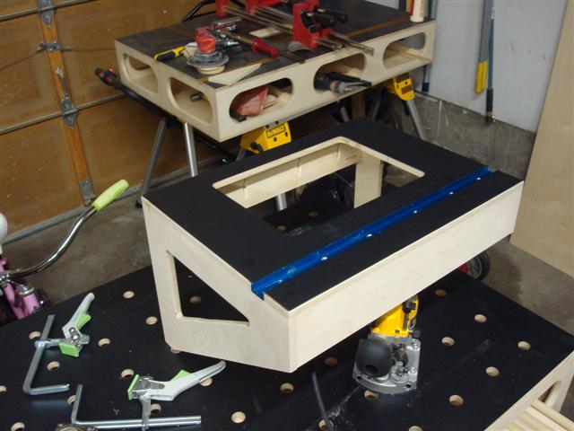
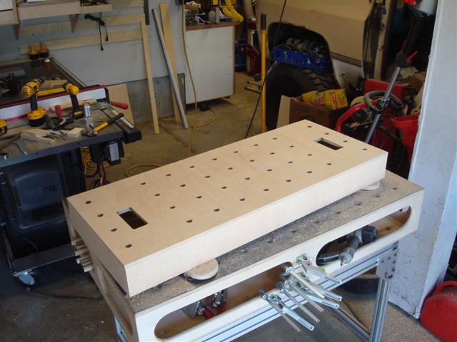
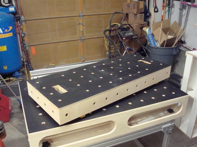
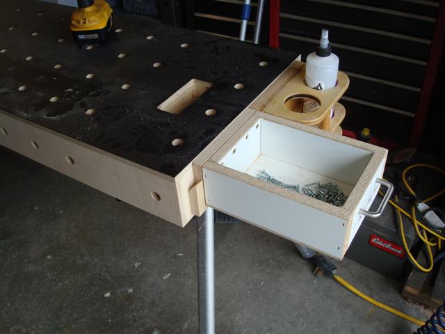
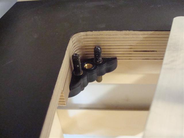
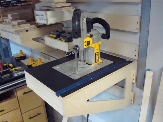
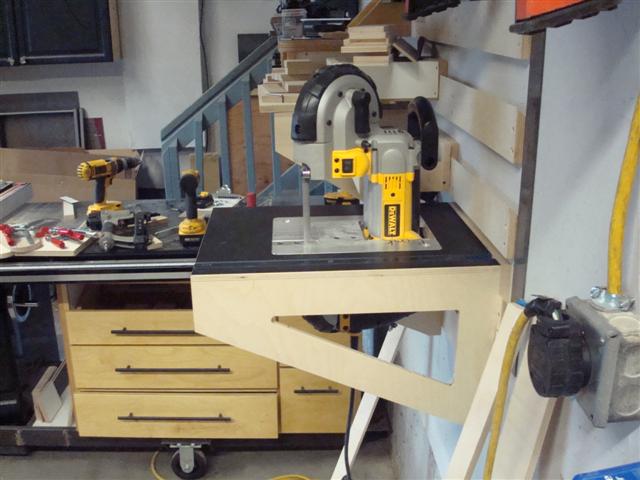
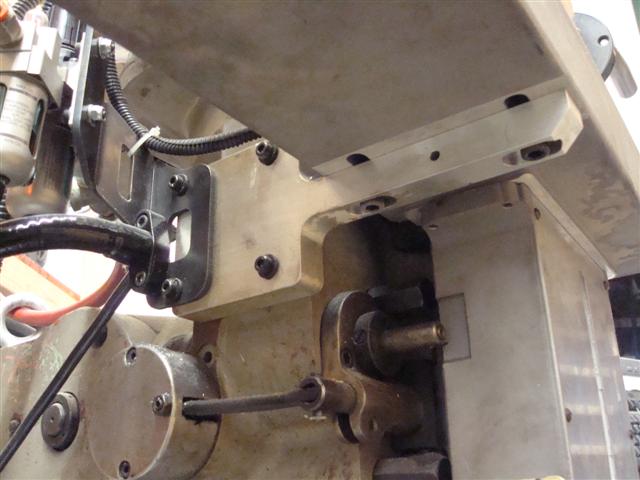
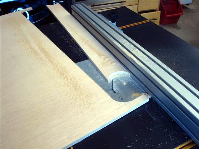
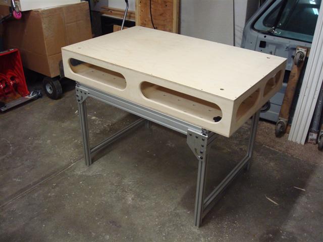
One of my character flaws is I can turn any 15 minute project into an all day project. I found out I didn't have even 6-inches of a 2x4 so I started fiddlin' around and when I was done, I had essentially built another MFT. The oblong slots in the box allow me to put my hand through and squeeze the release levers so I can remove it from the saw horse. The holes were machined using my router base and peg-board trick.

MMFT4.JPG


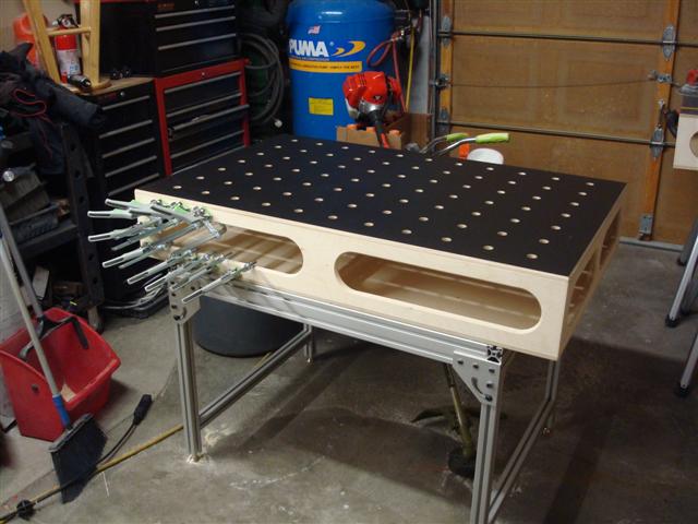
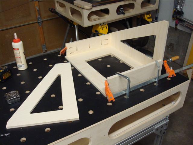
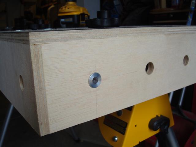
I also drilled the sides and ends so I could clamp on all surfaces. I built up the base with some scrap to get the exact height (though a washer ended up being the final touch to get the exact height).

MMFT5.JPG


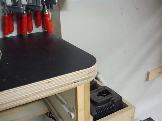
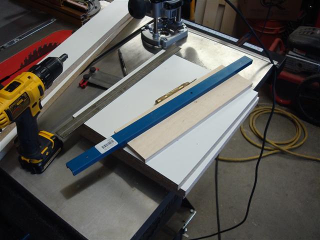
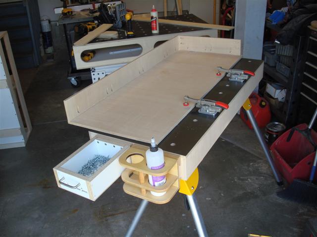
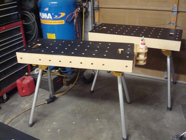
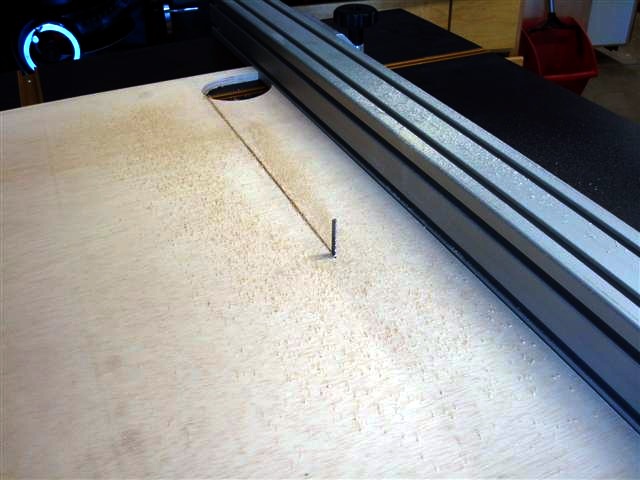
And laminated the surface like the rest of the MFT's.


MMFT6.JPG


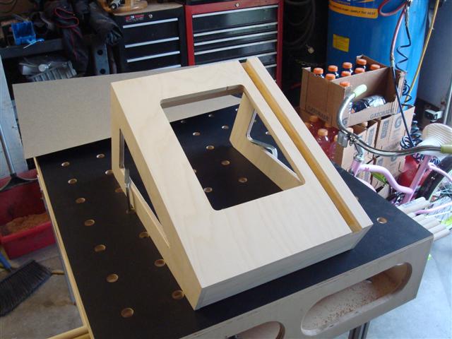
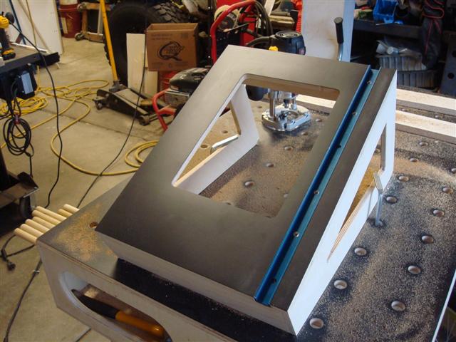
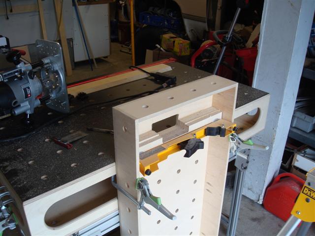
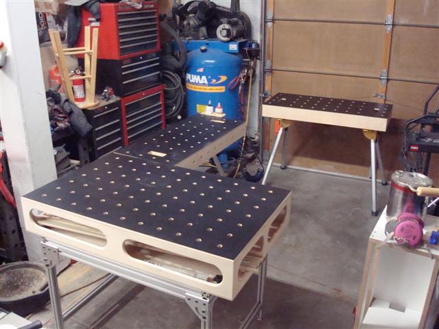
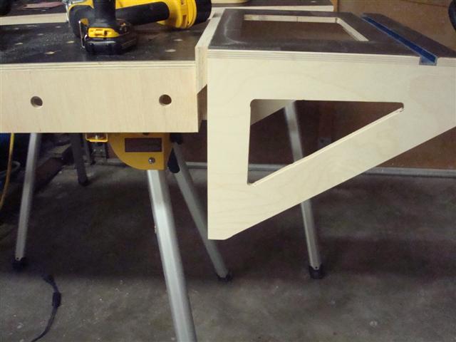
When slid up against the MFT, I get surface continuation. I can even clamp the two together inside if I don't want the saw horse to move while in use.

MMFT7.JPG


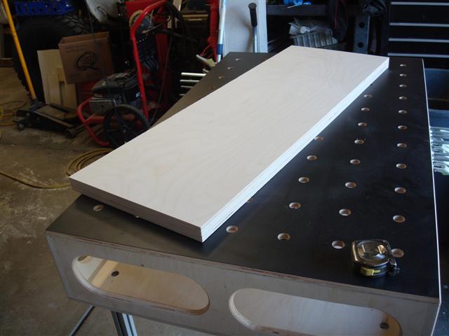
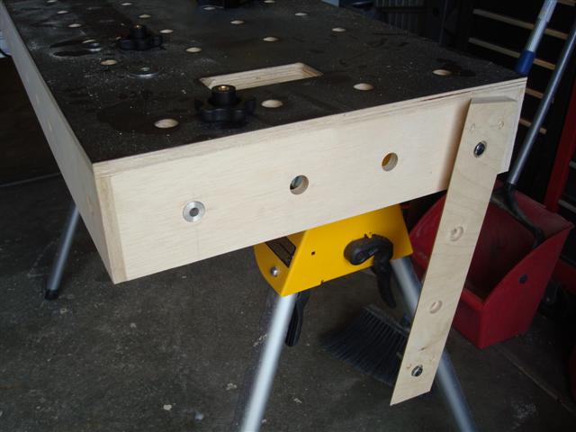
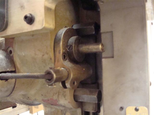
Then while I was about to assemble the other top I had an idea. I made some bushings out of aluminum that fit my 3/4-inch holes.

MMFT11.JPG


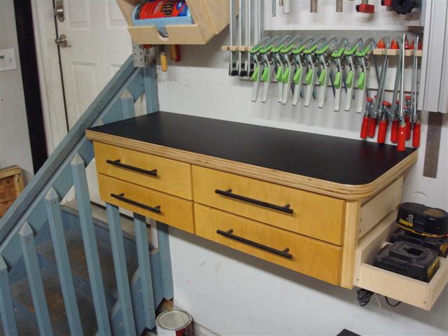
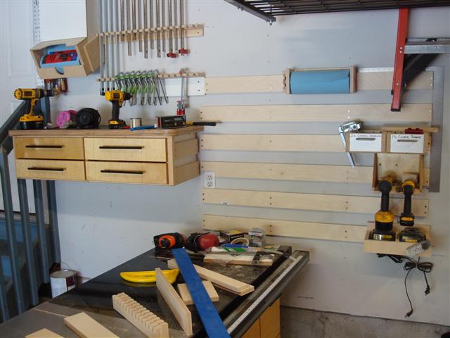
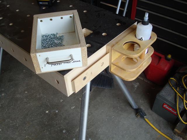
And modified a french cleat to have the same 4 inch wide hole spacing as the MFT's holes so I could attach the cleat to the table in any of the locations where holes exist.

MMFT12.JPG


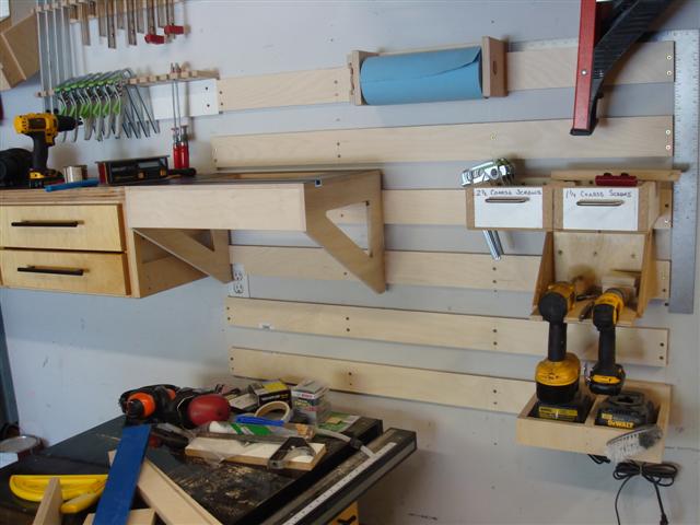
And now I can hang my tools, accessories, and other odds and ends off the side of the table so they're not taking up space.

MMFT13.JPG


Since all of my screw boxes have cleats off the back of them they can also hang off the side which keeps them easily accessible during assembly but not actually on the work surface which is really nice.

MMFT14.JPG


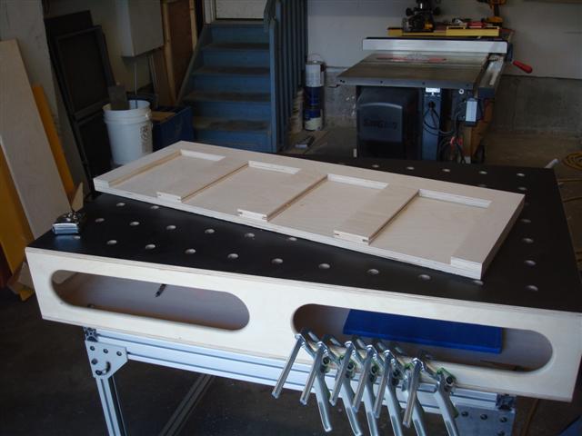
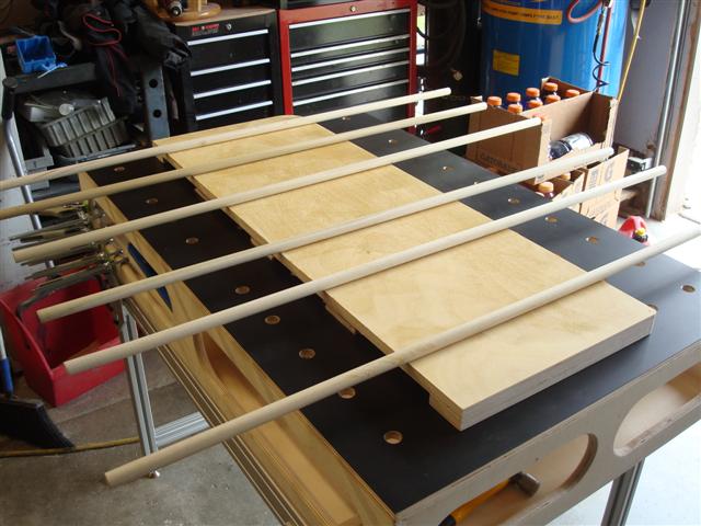
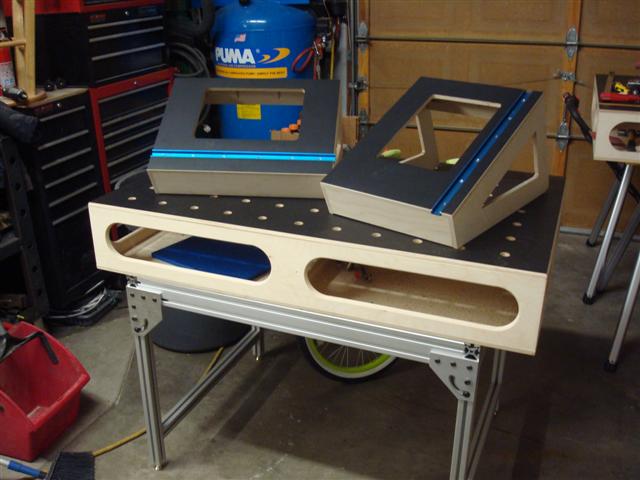
With the luxury of having more space I can now assemble the second one by using the first one. Having the MFT and the MFT-Horse I can now machine on one and assemble on the other which prevents me from moving things around during assembly - extremely nice.

MMFT20.JPG


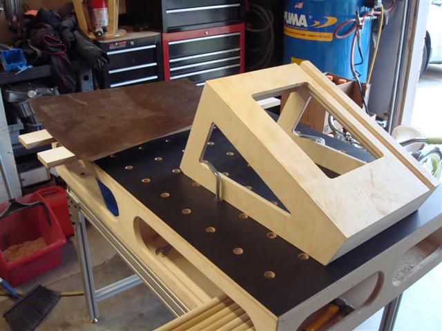
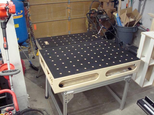
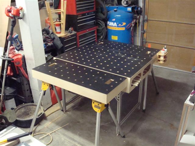
As soon as the second one is finished I played with a couple of different setups. Here's one clamped on either side of the MFT if I need a bigger table.

MMFT22.JPG


After moving them around a couple of ways this is what I think is the most likely configuration for most projects.

MMFT23.JPG


Talk about getting side-tracked. I started off wanting to work on the long MFT frame and instead I ended making a pair of smaller tables. I'm a little disappointed I didn't think of building them in the first place.

MMFT21.JPG
 
Last edited:

RobSmith

Banned
Joined
Feb 5, 2009
Messages
562
Location
NSW Australia
This next cabinet isn't novel. It's in every garage across the country. Spray paint, quarts of paint, filters, thread lick, the WD40 can...that stuff. I made three cabinets only as deep as they needed
to be so I could still get out/in.
vygatu8y.jpg

The bottom door was supposed to be able to be used as a work surface when it was open but the gas shock couldn't be mounted where it was possible. Could use a chain or cable or something.
qezetubu.jpg

You can shorten the strut by unscrewing the ball on the shaft, cut it back to the desired length and put a new thread on the end. the thread is usually a common one
 
OP
L

lilscorpion

Well-known member
Joined
Mar 15, 2010
Messages
3,599
Location
Colorado
You can shorten the strut by unscrewing the ball on the shaft, cut it back to the desired length and put a new thread on the end. the thread is usually a common one

Thanks for the idea, I'll have to look at it. Never even considered it but that makes total sense. Wonder if I can figure out a way to hold it in the chuck without wrecking the shock body...
 
OP
L

lilscorpion

Well-known member
Joined
Mar 15, 2010
Messages
3,599
Location
Colorado
Finished up one of the router buds today so I could use it with the band saw. Added these Kreg adjustable feet so I could trim out the plate on the accessories.

RB31.JPG


And then dropped in the saw and leveled it. Now I can make simple little cuts as needed and the bonus is the saw can stay in the bud while it's not in use.

RB32.JPG


The single french cleat is plenty strong but I'm thinking that maybe I should add a second one towards the bottom to help handle the weight.

RB33.JPG
 

nine4gmc

Well-known member
Joined
Mar 24, 2012
Messages
14,357
Location
Dallas
I kind of hate clicking on this thread, like I don't have enough projects going on and you just keep coming up with more great things like this... Joking of course, I love this thread!! Thanks for sharing your work, not many people with a talent like yours will take the time to post and show how and why they did what they did. I applaud you. :beer:
 
To avoid these ads, REGISTER NOW!

sideroad

Well-known member
Joined
Dec 9, 2013
Messages
84
Location
Goodna Queensland Australia
Re: Tool Organization

Great work. Love the hugely versatile nature of all the work surfaces. Regarding the strut shortening, could you thread on a die before cutting to length, cut new thread to needed length by holding the original threaded end with lock nuts/vice/etc and then cut the now un-needed/damaged thread off to length?


Sent from my iPhone using Tapatalk
 
OP
L

lilscorpion

Well-known member
Joined
Mar 15, 2010
Messages
3,599
Location
Colorado
Will the router buddies hang off the cleat and be flush to the MFT horse surface? If so, that would be awesome.

Man I wish. I thought of that but the designs conflict. The sawhorse top doesn't have material where the router buddy needs it for support. The power tool would be supported completely by the cleat which won't work. I probably could make it work off the side of the MFT (because there could be a support attached to the legs) but the horses is a no go.

rb34.jpg


I really need to laminate my mft top - that's so slick.

Gregor

I'll tell ya between adding so many mobile work surfaces all of which I can clamp things to using the Festool clamps \and laminating them, it's changed my productivity. Probably the only improvement I can think of is having one surface that doesn't have the holes in it so it could be used as a workbench. Last night I was using one of the MFT Horses and I kept dropping screws through the holes.

I kind of hate clicking on this thread, like I don't have enough projects going on and you just keep coming up with more great things like this... Joking of course, I love this thread!! Thanks for sharing your work, not many people with a talent like yours will take the time to post and show how and why they did what they did. I applaud you. :beer:

Thanks all of you for your feedback. The documentation of my projects has actually helped my productivity and creativity in the shop and it's left some fairly nice breadcrumbs for me to look back on along the way which, up until a few years ago, wasn't something I had much of.
 
OP
L

lilscorpion

Well-known member
Joined
Mar 15, 2010
Messages
3,599
Location
Colorado
Re: Tool Organization

Great work. Love the hugely versatile nature of all the work surfaces. Regarding the strut shortening, could you thread on a die before cutting to length, cut new thread to needed length by holding the original threaded end with lock nuts/vice/etc and then cut the now un-needed/damaged thread off to length?


Sent from my iPhone using Tapatalk

Now that's a really good idea! I messed with it for a little bit and couldn't get enough grip on it to get the head to come off. I doubt it's any more complicated than just threaded and screwed on. I got to the point where I was going to wreck it so the adult side of the brain decided to set it down and give myself some time to think about it before I make another attempt. Gut says that maybe a little heat to the plastic head (just a little with the heat gun) may be the best approach but some thought is in order so I don't end up having to order another one.

Thanks for the idea though...best one yet.
 

growler63

New member
Joined
May 4, 2014
Messages
3
Thanks for the idea, I'll have to look at it. Never even considered it but that makes total sense. Wonder if I can figure out a way to hold it in the chuck without wrecking the shock body...

Since I don't have the lovely toys you have, i'de have to do it by hand-determine the length-ish you need for that shaft, remove the ball head as mentioned by RobSmith , thread the die all the way on, stick the threaded end in the vise (or vise grips 'cause with MY projects, there's never enough to work with...lol) and cut the threads to the new length range, cut off the excess, spin the die off, clean the end off, done! One gas charged strut custom cut to length.
 

Kevin54

MEMBER EMERITUS
Joined
Jan 12, 2005
Messages
29,341
Location
Urbana, Ohio
Scorpion......About your mill.....is it a CNC retrofit, and if so, what brand of retrofit is it? I really need me a CNC mill :tantrum2:

As far as everything else you do, it is just over the top. I just look in awe at your postings and what you come up with. Absolutely fantastic. :rocker:

One last question....what is an MFT? Multi Function Table? :headscrat
 
OP
L

lilscorpion

Well-known member
Joined
Mar 15, 2010
Messages
3,599
Location
Colorado
Scorpion......About your mill.....is it a CNC retrofit, and if so, what brand of retrofit is it? I really need me a CNC mill :tantrum2:

One last question....what is an MFT? Multi Function Table? :headscrat

Kevin,

I did use a retrofit sold by ElrodMachine.com that utilizes a Centroid Controller/software. I originally selected it because the control has a conversational programming language that's simple enough for the dummy to learn and fancy enough to do just about anything for the more advanced user. He has some really neat ideas (like a conversion to add spindle indexing so you can rigid tap - link).

knee_cnc1.jpg


I also used some of ElrodMachine.com's conversion parts that he manufacturers himself and, after doing an install, I can attest that he has spent a bit of time on the designs and knows his stuff. Some other companies resell the brackets I believe but don't know for sure. The Z bracket (the quill kit - link has a variety of different options but I got the basic one (I think). What's slick about it is I can switch from 3-axis to 2-axis mid program so I can tap and then switch back into 3-axis mode to finish.

KneeMill1.jpg


What struck me as odd is that the kit essentially fits on any bridgeport or clone. This bracket bolts to existing bolt-holes to support the new servo bracket. I'd like to think ElrodMachine CNC's his own parts but don't really care.

KneeMill2.jpg


The bracket fits around all of the adjustments so you can still use all of the features on the mill (except the factory Z-axis feed).


KneeMill3.jpg


The X-axis servo box (Link Here) replaces one of the handles. I chose to go with the cast finish but I could have upgraded to powder coat. Didn't seem worth the money at the time but in hindsight I probably would have done it if I could do it all over.

KneeMill4.jpg


The Y-axis servo box also replaces the hand wheel and comes in two configurations (difference is where the servo sits). I got the one that tucks back behind to save space.

I did a variety of other things during the conversion like new precision ball screws. The only option I never did install is the flood coolant. At the time I thought it would be the ticket but I quickly learned (my CNC lathe) that coolant makes a mess of things and to avoid the mess on the mill I decided to cut dry. I may go with a mist system at some point but I've done without for so long I don't think about it much.

Regarding the ElrodMachine conversion - it's really simple and I'd recommend it. I had some problems getting the new CNC Heavy Duty Yolk in (my fault, I didn't know I needed to grind the casting and thought I had the wrong part) and was an idiot and opened up one of the zero backlash nuts (bearings all over the floor) but both of the mistakes were mine and didn't have anything to do with the kit. I think it took me a couple of weeks here and there which made it more difficult as well.

At the end of the day I used the mill for 3 years to make money and now it's a full time toy. Totally happy.

And yes, MFT = Multi-Function Table.
 
OP
L

lilscorpion

Well-known member
Joined
Mar 15, 2010
Messages
3,599
Location
Colorado
Just a quick update - working today on some material organization and I had an opportunity to use the jigsaw plate in the router table for the first time.

rtjp1.jpg


I let the blade cut (cross-cut) and didn't attempt to set a speed record and the result was a fantastic cut - almost equivalent to that of the table saw which really surprised me. What I failed to remember is that the downside would have the nicer cut (the jigsaw is up side down) so maybe I'll buy a blade designed to do the opposite (like for laminate).

rtjp2.jpg
 

kf4zht

Well-known member
Joined
Mar 20, 2008
Messages
712
Location
Calhoun, GA
What would you think of an MFT like bench top? I am going to put a bench along the back wall of my wood shop and like the design where you have a tool level and clamping ability. Downside that I can see is stuff falling through the holes. That and a big (4x8) mft in the middle with either an inset table saw or switch to a track saw.

I may have missed it, where the MFTs built with 1/2 or 3/4 ply? Which one would you use if you had to do it again.
 

Tyberius

Well-known member
Joined
Nov 26, 2013
Messages
312
Location
Wilmette, IL
I'll tell ya between adding so many mobile work surfaces all of which I can clamp things to using the Festool clamps \and laminating them, it's changed my productivity. Probably the only improvement I can think of is having one surface that doesn't have the holes in it so it could be used as a workbench. Last night I was using one of the MFT Horses and I kept dropping screws through the holes.

What's on the underside of the large MFT? Why couldn't you just flip it over and have a surface with no holes?
 
OP
L

lilscorpion

Well-known member
Joined
Mar 15, 2010
Messages
3,599
Location
Colorado
What's on the underside of the large MFT? Why couldn't you just flip it over and have a surface with no holes?


That thought was kinda confusing the way I said it. The large MFT does have a flat side with almost no holes that I use as a bench specifically for that reason too. What I meant to say was I might like to have a flat MFT-Horse with no holes in it too so I had the option on the MFT-Horse.

MFT64.JPG
 
OP
L

lilscorpion

Well-known member
Joined
Mar 15, 2010
Messages
3,599
Location
Colorado
What would you think of an MFT like bench top? I am going to put a bench along the back wall of my wood shop and like the design where you have a tool level and clamping ability. Downside that I can see is stuff falling through the holes. That and a big (4x8) mft in the middle with either an inset table saw or switch to a track saw.

I may have missed it, where the MFTs built with 1/2 or 3/4 ply? Which one would you use if you had to do it again.


I'm in the process of making my 8-foot workbench top right now so it's interesting timing to ask that question. I REALLY like the function of a top with holes in it so I can use it for fixturing. As you stated though, they kinda **** for using for anything else because of the holes. I'm surprised how many things don't fall through but I've had those moments where I spend more time picking things up of the floor than getting work done. I think the best answer is you need both surfaces because neither is perfect - which is why my MFT table has the two sides. My counter top/bench won't have holes in it because I use it for all kinds of things that have small(er) parts. If you can come up with a way to have both you'd be really happy.

My MFT tops are 1/2-inch Baltic birch with 3/4-inch Baltic Birch sides. I went more budget on the he MFT-Horse tops and sides by using 1/2-inch AC Ply. Not sure if they'll remain as straight or not but time will tell.
 
Last edited:

Tyberius

Well-known member
Joined
Nov 26, 2013
Messages
312
Location
Wilmette, IL
That thought was kinda confusing the way I said it. The large MFT does have a flat side with almost no holes that I use as a bench specifically for that reason too. What I meant to say was I might like to have a flat MFT-Horse with no holes in it too so I had the option on the MFT-Horse.

MFT64.JPG

So, it looks like you need a way to mount this:

MMFT5.JPG


on a flat surface, rather than recessed on the underside of the MFT.

That then means that your MFT's depth will be considerably shallower or, your sawhorses need to be considerably shorter at their smallest setting. I'm assuming they are set at their smallest setting now (if they do indeed telescope).

MMFT2.JPG


Can the horses be cut so that they are shorter?

Then you could build something that grips the sides of the MFT so that the worksurface is unmarred.
 

mdbeck1

Well-known member
Joined
Mar 7, 2010
Messages
2,297
Location
Norman, OK
You could machine some drop-in inserts.

...or make a flat surface with only a couple of pegs that he drops on top of the main table. It would work better if it had a groove around the top to catch things that tried to roll off.

...or maybe that's what you are describing?
 

Tyberius

Well-known member
Joined
Nov 26, 2013
Messages
312
Location
Wilmette, IL
...or make a flat surface with only a couple of pegs that he drops on top of the main table. It would work better if it had a groove around the top to catch things that tried to roll off.


...or maybe that's what you are describing?


No, but I thought about that. I figured the drop-in full top would be too heavy and present storage problems.

Something like this high tech rendering:
5esa6eba.jpg


u9umepuv.jpg


The inserts would stay in most of the time and only be removed one at a time when you wanted to use a clamp.
 
Last edited:

mdbeck1

Well-known member
Joined
Mar 7, 2010
Messages
2,297
Location
Norman, OK
I was thinking maybe a 24" X 24" (or whatever makes sense) piece of 3/4" ply with four of those same plugs on the back side. You could block off a piece of the workbench or if you have several of them you could block off the whole thing.
 
OP
L

lilscorpion

Well-known member
Joined
Mar 15, 2010
Messages
3,599
Location
Colorado
MMFT2.JPG


Can the horses be cut so that they are shorter?


Then you could build something that grips the sides of the MFT so that the worksurface is unmarred.


The legs could be cut down to make it shorter, hadn't thought of that. The clamps would need to be removed each time the surface was flipped ( not a huge deal I guess). The new problem would be getting to the release mechanisms on the attachments (on the existing design my hands go through the surface to release them,
 
OP
L

lilscorpion

Well-known member
Joined
Mar 15, 2010
Messages
3,599
Location
Colorado
No, but I thought about that. I figured the drop-in full top would be too heavy and present storage problems.

The inserts would stay in most of the time and only be removed one at a time when you wanted to use a clamp.


Inserts would work but, like in your drawing, would make the design much more difficult to make. The MFT holes would have to have a shoulder on each of them which makes for a two step operation and the material for the surface would need to be thicker than the 1/2-inch I used. Not impossible. The inserts could be press in and removeable. Neat idea...your right, they'd probably spend most of their life in the table. Guess the only downside is the time you'd spend on the lathe making the inserts (wish I had a CNC lathe).
 

lonestarky

Well-known member
Joined
Mar 28, 2011
Messages
367
Location
Lindenhurst IL
Re: Tool Organization

You could make another 1/2 top and use the four corner holes as dowel locators on the underside of the top. I figured the existing holes were not counter bored, so plugs wouldn't work. The other option is don't drop things. :)
 
To avoid these ads, REGISTER NOW!
Top Bottom