To avoid these ads, REGISTER NOW!

Truss Design

To avoid these ads, REGISTER NOW!
OP
M

Medeek

Well-known member
Joined
Jan 13, 2013
Messages
550
Location
Copalis Beach, WA
The low voltage module is working pretty good now. I just need to wrap up the 2D symbols and then we will see if I can put together a few typical load centers, and then its out to the public for some BETA testing.

A 2-gang, 12 port low voltage box is probably your worst case scenario:

electrical_su16_800.jpg


Each port can be assigned one of the following:

- CAT6
- CAT5e
- COAX
- PHONE (RJ11)
- RCA (Audio/Video, gold plated)
- BLANK (Plastic Insert)

Additionally each port has its own unique material/color which by default is "White". The faceplate can also be assigned a unique material/color.

Similar to other outlets the advanced options can be enabled which allows for vertical or horizontal mounting.

The number of possible QuickPorts is limited to the following:

1-Gang: 1, 2, 3, 4, 6
2-Gang: 8, 12

There are additional 2-Gang QuickPort wall plates that I have not added. I will only add these if requested, since they are already covered by the 1-Gang option.
 
OP
M

Medeek

Well-known member
Joined
Jan 13, 2013
Messages
550
Location
Copalis Beach, WA
Various combinations of QuickPorts yields a number of possible 2D symbols:

electrical_su17_800.jpg


I've tried to stay with conventional symbols as much as possible. Please let me know what you think on this.
 
OP
M

Medeek

Well-known member
Joined
Jan 13, 2013
Messages
550
Location
Copalis Beach, WA
Tomorrow I will finish modeling up some typical load centers (breaker boxes) like the one below (200 Amp, 40 Spaces):

electrical_su18_800.jpg


I'm not going to put any special logic into this module yet, just a simply positioning and selection. However at some point it would be really cool to use the plugin to setup the various breakers and identify circuits as well as assign specific elements to a circuit.

For now three sizes of breaker components are provided and it is up to the user to manually configure their panel if they so choose to do so, otherwise is is more representational than anything else.

When it comes to setting the vertical height of the load center what is the method used to measure from the floor? Center, Top or Bottom of the panel?

I will provide some common panel sizes (spaces): 24, 30, 40, 42, 54, and 60.

My breakers are based on the SquareD QO series as are my load centers however they are considerably simplified to maintain a low poly count.

Also for now I am only going to provide flush mount and not surface mount however I will probably enable both in the future.

View model here:

https://3dwarehouse.sketchup.com/model/560f7404-63e8-4b7f-9920-eb0775ae5e34/Load-Center-Example
 
OP
M

Medeek

Well-known member
Joined
Jan 13, 2013
Messages
550
Location
Copalis Beach, WA
The inside of these boxes and the breakers are very simple and low poly. The idea is mostly to convey the number and location of breakers and overall dimensions:

electrical_su19_800.jpg
 
OP
M

Medeek

Well-known member
Joined
Jan 13, 2013
Messages
550
Location
Copalis Beach, WA
Perusing the selection of electrical outlets and boxes at my local Ace Hardware this morning it became painfully obvious that I should have added the option for "amperage" to the outlet parameters.

Standard and Decora outlets now are available in 15A or 20A:

electrical_su21_800.jpg


I've never actually seen this type of outlet (NEMA 5-20R) installed in any residence I've ever lived at or in any new construction I've worked on but I'm sure it has its place.

Currently the 240V outlets are limited to only 30A and 50A outlets. At some point I may add in NEMA 6-15R and NEMA 6-20R if there is call for it.
 
OP
M

Medeek

Well-known member
Joined
Jan 13, 2013
Messages
550
Location
Copalis Beach, WA
First look at the output of the Light Fixture Module:

electrical_su24_800.jpg


electrical_su22_800.jpg


electrical_su23_800.jpg


The plugin allows you to drop your own light fixtures into the library sub-folder so you can have as many custom light fixtures as you like (and I don't need to spend anymore time modeling things up).

The fancy ext. wall lantern shown was simply downloaded from the warehouse, minor edit to make sure the origin of the file was in the correct place and then dropped into the light_fixture sub-folder. I will not be including this fixture in the distribution simply due to its size (1.2 Mb). However I will include some basic lampholders like the Leviton 49875 shown.

Another thing to note, since the light fixtures are custom I will not be attempting to apply any material or color to them. For that reason there is no need to explode the component into a unique group.

I will add some additional simple light fixtures and junction boxes as time allows or as requests are made.

Currently the light fixture tool is limited to wall mounted fixtures. I am still contemplating how best to deal with ceiling mounted fixtures and what type of system/organization to employ.
 
To avoid these ads, REGISTER NOW!
OP
M

Medeek

Well-known member
Joined
Jan 13, 2013
Messages
550
Location
Copalis Beach, WA
Pulling the global settings together:

electrical_su25_800.jpg


Outlets tab:

electrical_su26_800.jpg


The estimating piece will be after I release the BETA.

I'm almost ready to put this new plugin out there but I'm waffling on whether to spend some additional time on the draw tool and see if I can't make the plugin work with any (wall) geometry rather than just limiting it to an add on for the Medeek Wall plugin.
 
OP
M

Medeek

Well-known member
Joined
Jan 13, 2013
Messages
550
Location
Copalis Beach, WA
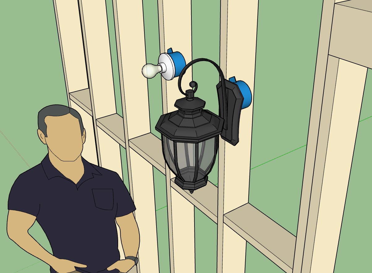
Version 0.9.0b - 02.15.2019
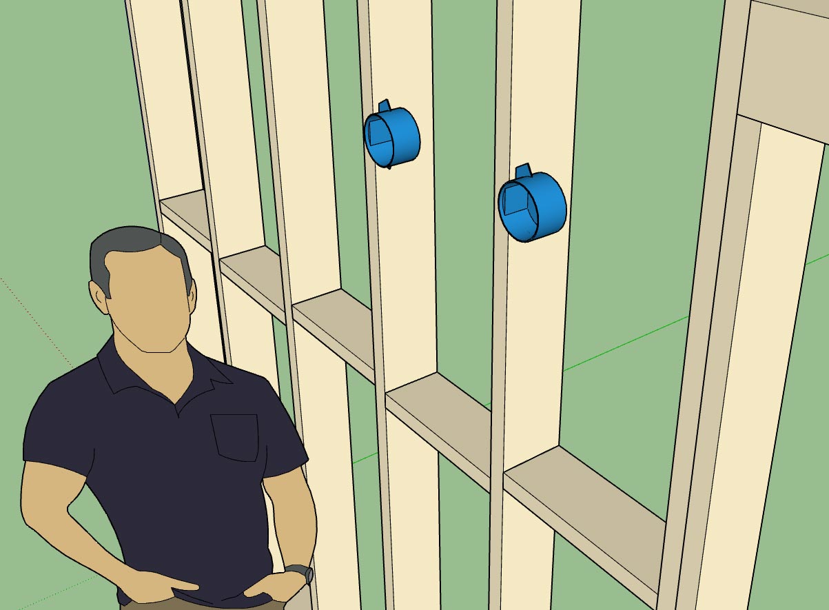
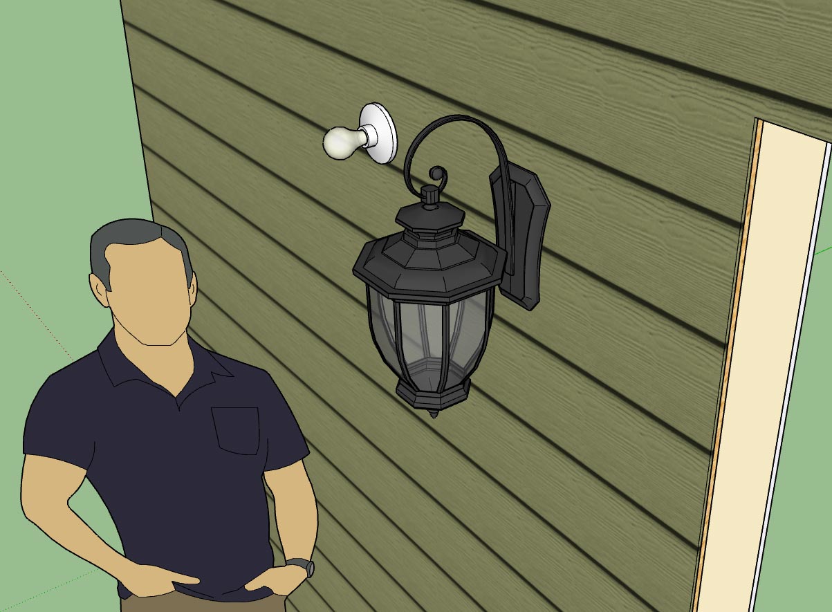
- Added additional Carlon and Raco octagon boxes into the Light Fixture module.

electrical_su29_800.jpg


Per customer request I've added some additional electrical boxes.

The full list of junction boxes available for light fixtures is:

Junction Boxes: Carlon (B518, B520, B620H), Raco (111, 112, 119, 128, 146, 164, 175, 177)

The reason I have to add these boxes in is because I need to hard code in the dimensions so that the plugin knows what the width is when the box justification is toggled to left or right. Its not a big deal, it only takes me a couple minutes to add in a new box and its dimensions.

If you have a particular box or light fixture you would like to see added please let me know.

As far as other international standards (British, France, South Africa etc...), I would be excited to add these in as well but I don't have the time or the energy to model up quality, low poly models of typical boxes, faceplates and electrical components. If you would like to see these added to the plugin I would need to have low poly models provided to me.
 
OP
M

Medeek

Well-known member
Joined
Jan 13, 2013
Messages
550
Location
Copalis Beach, WA
Version 0.9.1 - 02.16.2019
- Enabled the ability to draw switches with any wall geometry (removed the dependency on the Medeek Wall extension).

I've been blasted with emails the last couple of days requesting that I make the plugin work with any walls, so I figured I might as well see if I can make this happen.

This is largely experimentally at this stage since dealing with random (walls) geometry can be a bit tricky.

I've only enabled this feature with the Draw Switches tool for now. Once I am satisfied with its performance I can easily migrate it to all the other tools.

The wall must be a group, and its faces must be only one level deep, not nested group within group.

Please download this latest release and attempt to break it, let me know your findings.
 
OP
M

Medeek

Well-known member
Joined
Jan 13, 2013
Messages
550
Location
Copalis Beach, WA
Version 0.9.1c - 02.19.2019
- Enabled the ability to draw low voltage outlets, load centers and light fixtures with any wall geometry (removed the dependency on the Medeek Wall extension).

The plugin is now fully independent of the Medeek Wall extension and can function as a standalone extension.
 
OP
M

Medeek

Well-known member
Joined
Jan 13, 2013
Messages
550
Location
Copalis Beach, WA
Its funny how some of my best thinking is done when I am doing totally unrelated tasks. While I was cleaning out my garage and mini-van on Sunday afternoon I slowly started working out how to handle ceiling mounted light fixtures, almost unconsciously before I was aware that I was working on the problem.

After giving this topic a rest for a few days and then revisiting it again this evening it is now clear to me that in order for this to work properly I really need a "Story" or "Levels" module or plugin that actually works across all of the plugins. This Levels module is also needed for the other plugins in the mdkBIM suite, especially in relation to estimating.

This becomes critical for the electrical plugin because when you start placing fixtures into a ceiling you need to know where the floor is in relation to that ceiling. Or to be more precise you need to know which floor to assign the light fixtures to so that the 2D symbols are drawn at the appropriate Z height and hopefully are at the same level as the rest of the electrical symbols for that level (ie. wall mounted electrical fixtures), regardless of the ceiling height.

If the absolute Z height of the Level is changed then the 2D symbols assigned to it will need to move up or down to make the adjustment. The easiest way to do this is to place all of the 2D symbols (ceiling light fixtures only) in an over arching group that is separated from the separate light fixture groups themselves. When the Level Z height changes you only need to move this main group and not each 2D symbol.

The potential downside with this particular system is that if you manually move one of the light fixtures in the X-Y plane or laterally then the 2D symbol does not follow it and is out of sync (out of position). The way around this problem is to possibly setup an observer so that if a ceiling fixture is moved the 2D symbol is simply deleted and redrawn. When a ceiling fixture is deleted a similar situation occurs, however the symbol will always belong to the appropriate main group and have a tag (instance name) that matches the ceiling fixtures so that it can be easily purged from the main group.

The draw tool will not only be looking at the group (ceiling group) but also at the face when placing the fixture. The exact point selected on the face will determine the actual placement of the fixture. The height parameter (fixture to floor distance) as it is currently defined has no meaning and will be greyed out however for certain suspended fixtures it can be used at the "suspended height" thereby determining the height above the fixture to place the junction box within the suspended ceiling.

There is quite a bit to consider when it comes to ceiling mounted fixtures, I'm sure I haven't considered every possibility yet and there may even be a fatal flaw in some of the organization explained above but at least I wanted to get some of my thoughts down in writing before they evaporated away like a morning mist under the noon-day sun.
 
To avoid these ads, REGISTER NOW!
Top Bottom