To avoid these ads, REGISTER NOW!

Truss Design

OP
M

Medeek

Well-known member
Joined
Jan 13, 2013
Messages
550
Location
Copalis Beach, WA
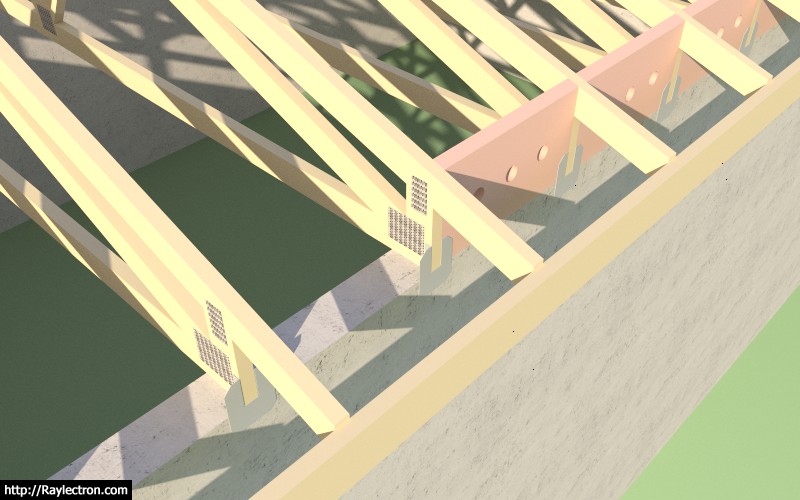
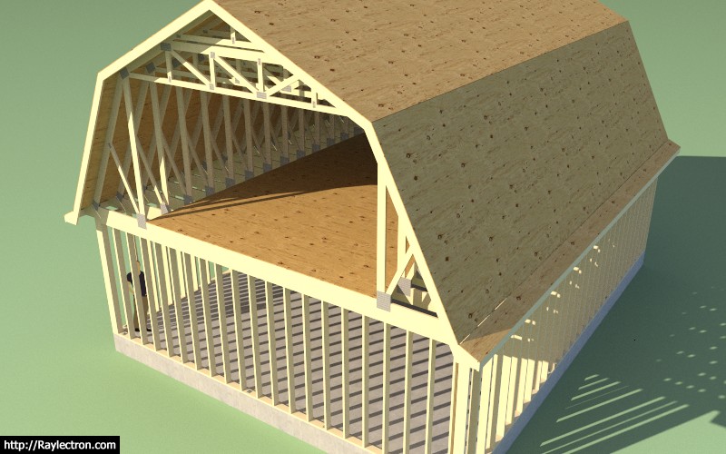
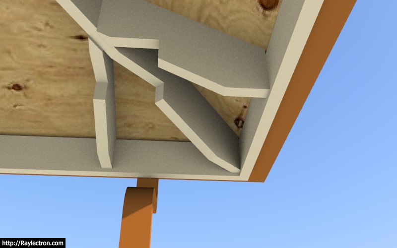
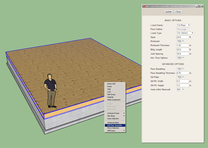
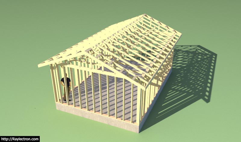
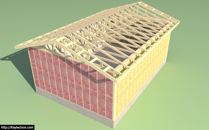
I am working on adding the heel blocking since it is an option listed in the advanced options.

truss_su324_800.jpg


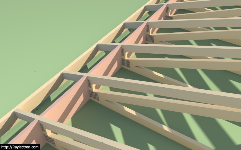
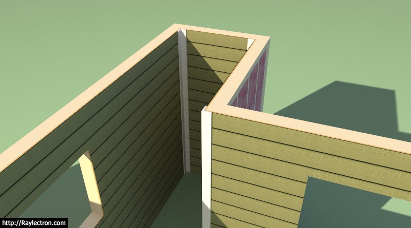
So far there has not been much call for this feature but a few people have inquired so I figured we might as well add it in for completeness. The red coloration is for clarity in the image above.

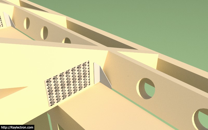
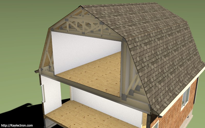
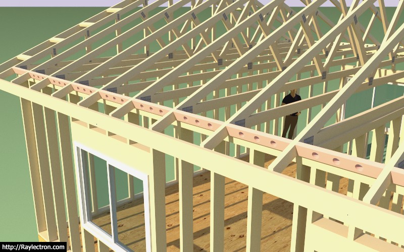
I will probably add the option to allow for venting holes since this is fairly typical in my neck of the woods.
 
To avoid these ads, REGISTER NOW!
OP
M

Medeek

Well-known member
Joined
Jan 13, 2013
Messages
550
Location
Copalis Beach, WA
Version 2.1.2 - 12.18.2017
- Enabled vertical and angled heel blocking within the advanced options for truss roofs.

truss_su325_800.jpg


If you choose to enable vent holes the heelblock menu will prompt for the hole diameter. The vent hole algorithm will place vent holes in the heel blocking per the truss spacing:

< 12 in. = 1 vent hole
< 16 in. = 2 vent holes
16 in. or greater = 3 vent holes

Let me know if this makes sense, I can always modify it to meet any criteria. If this sort of thing varies a lot per locale I can also make it more user definable.
 
OP
M

Medeek

Well-known member
Joined
Jan 13, 2013
Messages
550
Location
Copalis Beach, WA
I've been thinking about adding in the option to show H1 ties for rafters and trusses:

H1%20(inst).jpeg


I've seen them mounted both on the exterior and the interior with the flanges facing both inward and outward, four possible configurations. Any preference on how these are typically installed. I'm sure there is probably not much call for these but it isn't a big deal to add in the option for those that would like to use it.

I am currently featuring Simpson Strong-Tie hardware in the Truss Plugin, not because I am specifically endorsing their products or the brand but because that is what I am most familiar with and their products are readily available in the US and Canada. Mitek also makes comparable hardware and probably has better availability outside of the US and Canada.
 
OP
M

Medeek

Well-known member
Joined
Jan 13, 2013
Messages
550
Location
Copalis Beach, WA
Testing out the H1, H2.5A and H10A hurricane clips:

truss_su327_800.jpg


The plugin is now able to insert hurricane ties. I've currently set it up so that they are installed on the exterior of the framed wall with the flanges inward. Shown below is a Simpson H1 with angled vent blocks.

Here is an example using the Simpson H10A with vertical heel blocks and a raised heel truss connected to a masonry or concrete wall.

Ignore the vent holes in the blocking, I will provide additional options for venting in the near future.

Note that plugin automatically inserts these ties into the truss component, one on each end. The simplified H10A component is based on the official Simpson model found at the 3DWarehouse and is dimensionally accurate but with a much lower polygon count and hence much more lightweight.

truss_su328_800.jpg


Here is an example using the Simpson H2.5A hurricane tie. The upper tab is facing outward by default. The tie on the other end of the truss is positioned on the opposite of the truss to this one.

truss_su329_800.jpg


I will roll it out for trusses first and then rafter roofs at a later date.

I've specifically created simplified, lightweight versions of the hardware, so that the polygon count is minimal. With so many components I think it is imperative that the model is carefully constructed so as to minimize its polygon count and keep it as lightweight as possible.
 
OP
M

Medeek

Well-known member
Joined
Jan 13, 2013
Messages
550
Location
Copalis Beach, WA
Version 2.1.4 - 01.20.2018
- Completed energy/raised heels for attic trusses (2 variants: wedge and slider).
- Added floor sheathing and attic gypsum for attic trusses.
- Created a separate HTML menu for advanced options of attic trusses.
- Enabled gable end trusses for attic trusses.
- Hurricane ties enabled for attic trusses.

truss_su330_800.jpg


The gable end trusses for attic truss sets currently do not have any vertical studs as of yet, however the actual truss component is unique and different from the common attic trusses.

I also need to add in some logic for the gable end wall framing which is still absent. I am curious if anyone has experience or examples of this framed out, do you use a single or double top plate? I don't see a reason to use a double top plate in this situation.

Naturally the gable end wall may involve some windows or doors so there will be some overlap with the wall plugin, I am still thinking about how best to integrate the two plugins.
 

MEngineer

Well-known member
Joined
Apr 13, 2015
Messages
345
Location
Everett, Wa
In every instance I have been involved with regarding top plates, they are always double. It serves to tie the walls together more securely and also eliminates the need to have different length studs.
 

seber

Well-known member
Joined
May 31, 2016
Messages
4,192
Location
Deep East Tx.
If you plan on building a garage with a truss roof, you will still need to have an engineers stamp if you want to get a building permit. Ask me how I know.:lol_hitti

Tim

That would be true in Chicago but both of the states in which I have put up buildings (currently Texas) no such thing is needed. In fact in my current location there is not even a final inspection.
 
OP
M

Medeek

Well-known member
Joined
Jan 13, 2013
Messages
550
Location
Copalis Beach, WA
Bill Allen sent me this model today, and gave me permission to post about it. The structure has the following assemblies:

(3) attic trusses
(2) common trusses
(1) mono pitch truss
(1) scissor truss
(1) tail bearing truss
(3) valley sets
(1) gable roof rafter set

I was really quite impressed by the complexity of the model and the various roof lines. This model is just one of a number of iterations.

View model here:

https://3dwarehouse.sketchup.com/model/8210d003-2495-4d59-b68b-f6210af54dad/Attic-Truss-3
 
OP
M

Medeek

Well-known member
Joined
Jan 13, 2013
Messages
550
Location
Copalis Beach, WA
Worked on the license tab issue last night, I think I've got it fixed now, problem should be resolved for both Windows and Mac users

Please download the latest sub-release 2.1.4c and re-install the plugin.

I will slowly be switching to the new HtmlDialog which will mean that the plugin will no longer work on older versions of SketchUp (SU2016 and older). The reason for the switch to the new HtmlDialog from the deprecated WebDialog is the issues with modal windows (non-blocking) for the MacOS.
 
OP
M

Medeek

Well-known member
Joined
Jan 13, 2013
Messages
550
Location
Copalis Beach, WA
I've been making some progress on the advanced options for the gambrel attic truss. Since this type of roof has three different pitches it requires an entire rewrite of the advanced roof options module.

I've got the floor sheathing, fascia, rakeboard, roof sheathing and wall sheathing and cladding completed and working, see below:

truss_su334_800.jpg


The items still remaining are:

- gutters
- roof cladding and ridgecap
- heelblocking
- outlookers
- gypsum

I am still debating on how best to handle the gable wall framing, same scenario for regular attic trusses, I may just wrap that into the upcoming wall plugin, I'm not sure yet.

Even though this truss type is quite specialized it seems to also be quite popular hence my efforts to bring it up to speed with the common and attic truss.

I am slowly trying to bring each truss type up to the level that the common truss type is and have all applicable advanced options available.

I have decided to eliminate roof returns for the gambrel attic truss type for now, at some later date I may entertain adding that feature in for this truss type.
 
OP
M

Medeek

Well-known member
Joined
Jan 13, 2013
Messages
550
Location
Copalis Beach, WA
All of the remaining advanced options (gutters, gypsum, heelblocks, outlookers) are now in place for the Gambrel Attic Truss, at least as many as I am going to attempt right now. I still need to figure out structural outlookers for this truss type so that permutation of the outlooker option will be disabled for now.

Also note that for this truss type the heelblocking is only allowed to be vertically oriented, however I am willing to entertain angled heel blocks if someone can provide some form of documentation showing how they would be installed in a non-vertical orientation.

I have a bit more tidying up to do with the new Html menu for this truss type and then I should be able to roll it out tomorrow or this weekend.

truss_su335_800.jpg


truss_su336_800.jpg


View model here:

https://3dwarehouse.sketchup.com/model/88926fae-ba94-4bc9-94ea-b4fa4d726eb0/Medeek-Office-12
 
OP
M

Medeek

Well-known member
Joined
Jan 13, 2013
Messages
550
Location
Copalis Beach, WA
The crow's beak for the gambrel attic roof has been on my todo list for about a year and a half now. Grateful that I was able to somehow find the time to put this one together tonight.

The projection of the crows beak and the length along the rake can both be set by the user.

I will roll this out tomorrow as 2.1.5b once I've finished testing it.

truss_su339_800.jpg


truss_su340_800.jpg


View model here:

https://3dwarehouse.sketchup.com/mo...b04a59748212/Gambrel-Garage-with-a-Crows-Beak
 
OP
M

Medeek

Well-known member
Joined
Jan 13, 2013
Messages
550
Location
Copalis Beach, WA
The thing I find very interesting with the gambrel roof is the two pitches, whereas with your typical gable roof you only have one pitch and each side of the roof is simply the hypotenuse of half the span and the height of the peak.

With a gambrel roof you have the two legs of the roof and the two pitches and an infinite number of possible combinations and hence a large variety in the shape of the gambrel roof.

Ultimately this led me to create the HTML/SVG preview panel so that the user can play with the various parameters until the desired gambrel shape is achieved. I believe this is where the real power in this plugin in manifest, in situations where an architectural element can be realized by incrementally adjusting parameters within the user interface.

A common truss is much more simpler than the gambrel but a similar preview screen would be helpful in my opinion.
 
OP
M

Medeek

Well-known member
Joined
Jan 13, 2013
Messages
550
Location
Copalis Beach, WA
As I was creating the various test models for the gambrel attic truss yesterday I realized that the color I had initially set for the gypsum material was slightly off white, which for my particular case was just fine. However, after giving it second thought I realized that the gypsum color (material) should also be configurable so I added in one additional setting into the sheathing tab.

Then my 13 year old son (Jared) suggested that I implement some sort of color picker since most people don't equate a hexadecimal RGB value with any particular color (ie. #FF2C9F). I found a simple javascript based color picker and modified it to fit my needs, hopefully this is somewhat helpful.

Under the materials tab I will probably implement similar options where one can modify the color of the lumber and the pressure treated lumber. For now I will probably keep the plywood and the OSB material/texture as default. If someone really wants to modify those it is simply a matter of replacing the .jpg image with their own custom image within the plugin folder.

Since javascript tends to be a bit browser dependent I am curious how well this works on MacOS with the background browser running as Safari, please let me know if there are any issues.

The color boxes at the bottom of the color picker provide some shades of grey as well as the default Medeek colors for: lumber, pressure treated lumber, gypsum.

This minor update is rolled into sub-revision 2.1.5c.

https://scontent-sea1-1.**.fbcdn.net/v/t1.0-9/28059113_10214266432122027_4669586998471107624_n.jpg?oh=fb58720238d1b489fbb2d9d4207ab84d&oe=5B1C6DA9
 
To avoid these ads, REGISTER NOW!
OP
M

Medeek

Well-known member
Joined
Jan 13, 2013
Messages
550
Location
Copalis Beach, WA
I've been giving some thought to framed openings in floors, see image below:

truss_su353_800.jpg


Generally, at least from what I've seen most holes in floors are either rectangular, L-shaped or U-shaped, but I guess any outline is possible.

What I've shown in the image above is LSL or LVL framing out the opening however the actual framing might be significantly different depending on what is supporting the floor below.

In some cases the rectangular opening might not be supported by bearing walls from below, in that case the two LSL boards running parallel to the joists would probably be larger beams and the headers would be hangered from these beams and would also probably be more substantial.

The point is how to make this feature flexible enough to accommodate most framed openings but at the same time keeping it as simple as possible so the user is not overwhelmed with parameters.

View model here:

https://3dwarehouse.sketchup.com/model/a879f0c7-0900-47f5-9caf-acc1c3a53f25/Framed-Opening-TJI-Floor

Any ideas would be greatly appreciated.

P.S. I am also going to make this feature editable so that the actual hole can be altered after the fact. This should be an interesting programming challenge.
 
OP
M

Medeek

Well-known member
Joined
Jan 13, 2013
Messages
550
Location
Copalis Beach, WA
Version 2.1.8 - 03.18.2018
- Enabled the "Edit Floor Assembly" function for all I-Joist floors (imperial and metric units): TJI, BCI, LPI, Red-I, PKI.

truss_su356_800.jpg


Now I just need to get the floor framed opening feature working and then this module might actually be useful.

Realize that any manual edits made to the floor assembly are blown away when you use the edit function. It is essentially re-drawing the entire floor assembly, the same goes for the roof truss assembly edit feature.
 
OP
M

Medeek

Well-known member
Joined
Jan 13, 2013
Messages
550
Location
Copalis Beach, WA
OP
M

Medeek

Well-known member
Joined
Jan 13, 2013
Messages
550
Location
Copalis Beach, WA
In the global settings you can enable a 3D preview:

wall_su8_800.jpg


The 2D preview is default, which just shows the footprint of the wall.
 
OP
M

Medeek

Well-known member
Joined
Jan 13, 2013
Messages
550
Location
Copalis Beach, WA
I am now testing the stud placement and top and bottom plates:

wall_su10_800.jpg


So far only the line tool is available but seems to work fairly robustly now.

Please download and comment on the model below:

https://3dwarehouse.sketchup.com/model/a3100fa6-7f73-48be-9c52-92c903c5b29f/Framing-Test-1

There are a few minor issues that need further attention:

1.) How to position studs with non-orthogonal walls, I could use some direction on this.
2.) I have California Corners enabled for outside corner and inside corners, what do you do when there is a clash between the nailer and the regular stud layout, see model for examples.
3.) When there is more than one top plate (2,3 etc...) I have them setup to lap each other. However multiple bottom plates do not lap, they are currently setup just to stack.

The items for tomorrow's programming todo list are:

- Setup the HTML form and backend for the wall edit feature.
- Finish cleaning up the global settings, HTML and backend.
- Further debugging and refinement of the stud placement module.

Future items:

- Addition of window and door modules (framed openings)
- Advanced wall options (sheathing, cladding, gypsum, insulation, trim, holdowns etc...)
- Window and Door Plugin
- Gable Wall Tool
- Polyline tool for Rectangular Wall Tool

I'm sure there are plenty of other items that don't come to mind right this minute, please feel free to pass along any thoughts, comments or suggestions.
 
OP
M

Medeek

Well-known member
Joined
Jan 13, 2013
Messages
550
Location
Copalis Beach, WA
Working on the advanced options this morning, I've added in sheathing, cladding and gypsum:

wall_su11_800.jpg


As windows and doors are added to the wall they will automatically cut holes into the framing and these three other building layers. The code to cut holes in solids is actually not to difficult, I developed it with the foundation plugin when I needed to add foundation vents into stemwalls.

I will probably put the cavity insulation and the holdowns on the backburner for a a while as I focus on the wall edit function and the window and door (framed opening) module.

I've also added one additional (Tee Corner) corner configuration for each end of the wall.

I will also be adding in two additional parameters so when you edit a given wall panel you can offset the sheathing and cladding above or below the actual wall panel to tie into a rim joist above or below. Some contractors also like to lap the sheathing and cladding over the foundation rather than having it flush with the sill/bottom plate.

On a similar note it might also be useful to allow the user to set the bottom plate as pressure treated (ie. garages where the wall is directly in contact with the foundation). I'm not sure yet where I want to put this parameter.
 
OP
M

Medeek

Well-known member
Joined
Jan 13, 2013
Messages
550
Location
Copalis Beach, WA
PT bottom plate option added into the first menu.

The little structure below is not much to look at (no windows or doors yet) but it is the first time I've been able to create an entire building envelope with absolutely no manual editing of the SketchUp model. This in itself is a major break through for me. I used all three plugins to create the model: Foundation, Truss and Wall.

wall_su12_800.jpg


wall_su13_800.jpg


All principal architectural elements are there: sheathing, cladding, gypsum, anchor bolts, rebar, concrete, roof cladding, gutters etc...

The only items missing are exterior and interior trim/molding and of course the windows and doors.

My next push will be the windows and door module.

The time required to create the walls was under a minute however once I have the polyline tool enabled this will cut down the initial wall creation time to literally seconds.

Insertion of doors and windows will always take a bit longer primarily because the designer actually needs to determine where they want to place their openings. There is not much one can do about that other than to make the actual placement/insertion process as intuitive and automated as possible.
 
OP
M

Medeek

Well-known member
Joined
Jan 13, 2013
Messages
550
Location
Copalis Beach, WA
The wall edit feature is now functional and seems to be fairly robust:

wall_su14_800.jpg


The wall edit menu shown above.

Originally I was going to have all the windows and doors load up within this same menu but given how big it has grown already I think a separate edit menu for door and windows would be more practical.

I will also need to add in some additional code so that when certain parameters are modified in the wall edit menu those changes are then propagated to other wall panels that are assigned to the same wall group letter.
 
OP
M

Medeek

Well-known member
Joined
Jan 13, 2013
Messages
550
Location
Copalis Beach, WA
The cavity insulation option in the advanced options will fill in the wall cavities with insulation:

wall_su16_800.jpg


wall_su17_800.jpg


This feature will only get more interesting as windows and doors are added.

I supposed there will be some utility to this option for some since it will allow the designer/contractor to calculate the volume of insulation needed with fairly decent accuracy.

I could use some better textures for my insulation, the ones shown are pink and yellow fiberglass, rockwool and cellulose. I also have a blown fiberglass (white) not shown.

View model here:

https://3dwarehouse.sketchup.com/mo...c78c7ac3f70f/Framing-Test-4-Cavity-Insulation

I've now started wading into the window and door module, this may take me a 2-3 days to sort out since it is fairly complicated.
 
OP
M

Medeek

Well-known member
Joined
Jan 13, 2013
Messages
550
Location
Copalis Beach, WA
Since the model can get quite heavy with all of the studs, blocking, insulation and other geometry I've decided to add one additional option to the basic parameters called "Wall Framing". By turning this option to "NO" the walls are drawn with all of the internal geometry removed (ie. plates, studs, headers, kings, trimmers, insulation, holdowns etc...)

However, you can still use the advanced wall options and display sheathing, cladding and gypsum:

wall_su19_800.jpg


The model is now quite boring but is significantly more lightweight and will lend itself to quick edits by the designer. Walls and Doors can be inserted and all of the internal framing can be turned on at any time within the wall edit menu.

See model here:

https://3dwarehouse.sketchup.com/model/e1d92198-f073-4eca-b5e5-d87f7d10aafe/Framing-Test-6

The wall framing parameter will also be available within the global settings so that its default behavior can be set.

Notice how certain parameters are grayed out in the wall edit menu when wall framing is turned off, this is by design.
 
OP
M

Medeek

Well-known member
Joined
Jan 13, 2013
Messages
550
Location
Copalis Beach, WA
I've been looking at some screen shots from Chief Architect and giving some thought to framed opening headers and their trimmers.

Beyond the myriad of options I am already providing for window and door headers I may need to extend the list to a few others.

The current list is:

4X4
4X6
4X8
4X10
4X12
6X4
6X6
6X8
6X10
6X12
(2) 2X4
(2) 2X6
(2) 2X8
(2) 2X10
(2) 2X12
(3) 2X8
(3) 2X10
(3) 2X12
1-3/4X7-1/4 LSL
1-3/4X9-1/4 LSL
(2) 1-3/4X7-1/4 LSL
(2) 1-3/4X9-1/4 LSL

For larger doors (garage doors) glulams are fairly typical in my neck of the woods. If the designer selects glulam an additional menu will pop up that allow for the selection of the exact glulam size. I've already implemented a similar feature in the Truss Plugin for glulam rafter roofs.

I think it might also be interesting to provide an auto calculate feature based on the width of the framed opening:

- AUTO GLULAM
- AUTO 2X
- AUTO 4X
- AUTO 6X
- AUTO LSL

This is not an exact engineering solution since we don't know the loads on the header but it could at least get it ball park. Future releases of the plugin will have more engineering capabilities added so that one can actually run the actual numbers on a header (I'm think Forte type software here, one that I commonly use in my own practice).

Along the same lines another parameter should be added into the global settings to allows for auto-calculation of the door/window trimmer qty., again this would be based off of the width of the framed opening and also factor in whether the wall is an interior or exterior wall.
 
OP
M

Medeek

Well-known member
Joined
Jan 13, 2013
Messages
550
Location
Copalis Beach, WA
I've separated the cladding and sheathing vertical offsets (top and bottom) into separate parameters so you can now offset each independently of each other:

wall_su27_800.jpg


Notice the two value in the edit wall menu for the offsets. This should allow for maximum flexibility, however the addition of more parameters might make the entire interface more overwhelming to some.
 
OP
M

Medeek

Well-known member
Joined
Jan 13, 2013
Messages
550
Location
Copalis Beach, WA
Here is my draft for Window Casing (Style A):

wall_su31_800.jpg


View model here:

https://3dwarehouse.sketchup.com/mo...6ebb/Window-Casing-Style-A-Medeek-Wall-Plugin

The parameters will probably be:

Head Casing Width: 5.5"
Side Casing Width: 3.5"
Apron Width: 2.5"
Jamb Ext. Depth: 2.5"
Casing Thickness: 0.75"
Stool Thickness: 1.0"
Apron Thickness: 0.75"
Jamb Ext. Thickness: 0.75"
Header Extension: 0.0"
Stool Extension: 1.0"
Apron Extension: 0.5"
Stool Projection: 1.25"
Casing Reveal: 0.25"
Shim Gap: 0.25"

The values given are the default values and coincide with the model given above.

Some details show shims between the framing and the jamb extensions, others do not:

woodwindowsectiondwg.jpg
 
To avoid these ads, REGISTER NOW!
Top Bottom