To avoid these ads, REGISTER NOW!

Vintage Craftsman Drill Press

Slowjoe

Active member
Joined
Dec 3, 2015
Messages
31
Location
Port Clinton, Ohio
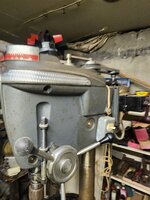
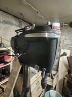
Hey! Last Sunday, I picked up this Craftsman DP. It has no model badge, but it is in GREAT shape. The original paint is all there with just a few scratches, and it needs a cleaning. The Vari-Slo appears to be intact. It also came with a milling vise, shown on the table and on the base after I moved it.)20240428_092830.jpg20240428_092844.jpg20240428_092846.jpg20240428_092849.jpg20240428_092853.jpg I think with some serious cleaning and a good lube, this unit will be ready.
 
To avoid these ads, REGISTER NOW!

FrankLee

Well-known member
Joined
Sep 13, 2010
Messages
3,634
Location
seMI, 48317
WOW! So much greatness in that one. Very nice score, Joe!

The head is early to mid '50s. The model number would be 103.23131, if it was originally a bench-top, or 103.23141, if it was originally a floor standing model.


It looks like it's a hybrid machine. The base is not Craftsman and I can't see the table under the pan. I don't recognize that column collar near the base either.

What about the column? We discussed how the top of Craftsman columns were milled inside.

The hold-down clamped to the column above the table is a Craftsman accessory. Craftsman also sold those Furnas F/R switches.

Are the tilting vise and rotary table branded "Craftsman"? IIRC, they were both made by Palmgren.


WOW!
 
Last edited:
OP
S

Slowjoe

Active member
Joined
Dec 3, 2015
Messages
31
Location
Port Clinton, Ohio
Hi Jim. I haven't had the chance for a close inspection of the column or table. I'll get to that this weekend and let you know.
BTW, on those parts I got...
I disassembled the Jacob's chuck, and some of the teeth are broken off of the jaws. I think that tells me that somebody cranked really hard on the key when locking down on small bits (depending on the jaw, only the last 1 or 2 teeth are broken/missing). I don't recall for sure, but I think it's a 63A (or 633A?). Is the 64A the standard chuck for that machine? Do you by chance have replacement jaws, or a good chuck. This one has that safe lock feature, which I like.
Thanks.
Joe
 

FrankLee

Well-known member
Joined
Sep 13, 2010
Messages
3,634
Location
seMI, 48317
Hi Jim. I haven't had the chance for a close inspection of the column or table. I'll get to that this weekend and let you know.
Yes, please do.

BTW, on those parts I got...
I disassembled the Jacob's chuck, and some of the teeth are broken off of the jaws. I think that tells me that somebody cranked really hard on the key when locking down on small bits (depending on the jaw, only the last 1 or 2 teeth are broken/missing).
That is a bummer. Cleaning that chuck was going to be my project last Friday. I would have discovered the broken teeth.

If the end teeth were broken off, more likely, someone pressed the sleeve on without extending the jaws. Typically, over-cranking the key will break the teeth on the sleeve.

I don't recall for sure, but I think it's a 63A (or 633A?). Is the 64A the standard chuck for that machine?
The Jacobs 6A chuck was standard on 100s until 1951-ish
I believe that is a Jacobs 633C and was standard on the 100s and 150s from 1951-ish to 1966.

Do you by chance have replacement jaws, or a good chuck.
I think I have a set of jaws and a split nut. I'll check.

This one has that safe lock feature, which I like.
Thanks.
Joe
 
Last edited:

crguy

Well-known member
Joined
Jan 24, 2016
Messages
2,675
Location
SW Washington
Those with the Vari Slo are neat! Don't force it when adjusting the speed as the castings aren't all that strong. I'd sell the rotary table to someone with a milling machine. That drill press isn't designed to be used for milling work.
 
OP
S

Slowjoe

Active member
Joined
Dec 3, 2015
Messages
31
Location
Port Clinton, Ohio
Those with the Vari Slo are neat! Don't force it when adjusting the speed as the castings aren't all that strong. I'd sell the rotary table to someone with a milling machine. That drill press isn't designed to be used for milling work.
Yeah, my thoughts exactly. I wish I did have a Bridgeport, but since I don't, and probably never will, I'll sell it. Any idea of the worth? It, too, looks to be in excellent shape.
 

crguy

Well-known member
Joined
Jan 24, 2016
Messages
2,675
Location
SW Washington
Yeah, my thoughts exactly. I wish I did have a Bridgeport, but since I don't, and probably never will, I'll sell it. Any idea of the worth? It, too, looks to be in excellent shape.
Look on Ebay to see what they have sold for. Palmgren is one of the makers of those.
 

Snip's

Well-known member
Joined
Apr 29, 2017
Messages
1,879
Location
Ohio
Congratz on the DP....
Lots of goodies on that one...

Is that a Welch 1100 Cam-Lock Drill Press Clamp?
Screen Shot 2024-05-02 at 4.23.19 PM.png
 
OP
S

Slowjoe

Active member
Joined
Dec 3, 2015
Messages
31
Location
Port Clinton, Ohio
WOW! So much greatness in that one. Very nice score, Joe!

The head is early to mid '50s. The model number would be 103.23131, if it was originally a bench-top, or 103.23141, if it was originally a floor standing model.


It looks like it's a hybrid machine. The base is not Craftsman and I can't see the table under the pan. I don't recognize that column collar near the base either.

What about the column? We discussed how the top of Craftsman columns were milled inside.

The hold-down clamped to the column above the table is a Craftsman accessory. Craftsman also sold those Furnas F/R switches.

Are the tilting vise and rotary table branded "Craftsman"? IIRC, they were both made by Palmgren.


WOW!
Hi FrankLee. The rotary table is exactly like the one on my 103.23140 DP. It has the number 27213-103 cast into the underside. I'll check out the column tomorrow.
 

RTM

Well-known member
Joined
May 13, 2019
Messages
13,411
Location
SF Bay Area

FrankLee

Well-known member
Joined
Sep 13, 2010
Messages
3,634
Location
seMI, 48317
Last edited:

Nick Rivers

Well-known member
Joined
Mar 19, 2024
Messages
261
Location
USA
I see two different rotary tables in the photos by looking at the crank handles. Those combined are worth more now than the drill press. I would not sell them.
Rotary tables are useful on a drill press for lining up precise drill locations using the X and Y axes.
 

gatewaysysop

Well-known member
Joined
Nov 11, 2008
Messages
3,310
Location
Arizona
I see two different rotary tables in the photos by looking at the crank handles. Those combined are worth more now than the drill press. I would not sell them.
Rotary tables are useful on a drill press for lining up precise drill locations using the X and Y axes.

This. I have one like the model shown on the base. Mine is branded Craftsman, marked as made in Japan. Superbly made and I would not part with it. Once you've had one to line things up just right, you will wonder how you managed without, especially if like me you don't have a mill and have to make do with a drill press somehow.
 
OP
S

Slowjoe

Active member
Joined
Dec 3, 2015
Messages
31
Location
Port Clinton, Ohio
Hi Jim. I haven't had the chance for a close inspection of the column or table. I'll get to that this weekend and let you know.
BTW, on those parts I got...
I disassembled the Jacob's chuck, and some of the teeth are broken off of the jaws. I think that tells me that somebody cranked really hard on the key when locking down on small bits (depending on the jaw, only the last 1 or 2 teeth are broken/missing). I don't recall for sure, but I think it's a 63A (or 633A?). Is the 64A the standard chuck for that machine? Do you by chance have replacement jaws, or a good chuck. This one has that safe lock feature, which I like.
Thanks.
Joe
Hey there, Jim. I got some measurements of the column:
62" LOA column,
1 end is 2-95/128" OD and 2-53/128" ID
the other end is 2-95/128 OD and 2-29/64" ID.

FYI, the 103.23140 column is 65-7/8" LOA
2-97/128" (2-3/4") OD & 2-51/128" ID @ top
2-95/128" OD & 2-23/64" ID @ bottom

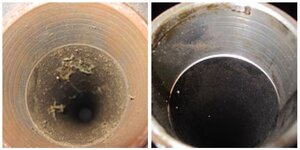
How do you clean the crud from inside of the columns?
Joe
 

FrankLee

Well-known member
Joined
Sep 13, 2010
Messages
3,634
Location
seMI, 48317
Hey there, Jim. I got some measurements of the column:
62" LOA column,
1 end is 2-95/128" OD and 2-53/128" ID
the other end is 2-95/128 OD and 2-29/64" ID.

FYI, the 103.23140 column is 65-7/8" LOA
2-97/128" (2-3/4") OD & 2-51/128" ID @ top
2-95/128" OD & 2-23/64" ID @ bottom

How do you clean the crud from inside of the columns?
Joe
Are any of those column IDs machined ~2" deep? If so, that is a K-S Craftsman column. I'm not aware of any other manufacturer who machined just the top ID.
0136.JPG

The column height was reduced from 67" to 62" in the 1956 model year. I'm not sure what to conclude about the 23140 column height and the differences in the top and bottom OD and ID dimensions. The 65-7/8" height does not sound like mid-'40s to mid-'60s era Craftsman.


I just push a dry wadded-up rag through the column with a broom stick and don't worry about what's left.
 
Last edited:
To avoid these ads, REGISTER NOW!
OP
S

Slowjoe

Active member
Joined
Dec 3, 2015
Messages
31
Location
Port Clinton, Ohio
Hey there, Jim. I got some measurements of the column:
62" LOA column,
1 end is 2-95/128" OD and 2-53/128" ID
the other end is 2-95/128 OD and 2-29/64" ID.

FYI, the 103.23140 column is 65-7/8" LOA
2-97/128" (2-3/4") OD & 2-51/128" ID @ top
2-95/128" OD & 2-23/64" ID @ bottom

How do you clean the crud from inside of the columns?
Joe
Hi. I got the package yesterday. Thank you.
What are the 10-32 x 3/4" screws for?
 

FrankLee

Well-known member
Joined
Sep 13, 2010
Messages
3,634
Location
seMI, 48317
Those are 10-32?
I meant to include 8-32 x 3/4" for the spindle pulley retaining screws. The originals are always(?) damaged or broken on the 80 and 100 series drill presses that don't have the snap ring on the lower quill.

Do you think those chuck jaws will work?
 
OP
S

Slowjoe

Active member
Joined
Dec 3, 2015
Messages
31
Location
Port Clinton, Ohio
My mistake, they are 8-32. I should have taken them out of the bag to look at them.
The jaws look like they should work. I'll be rebuilding the chuck soon, so I'll let you know.
 
OP
S

Slowjoe

Active member
Joined
Dec 3, 2015
Messages
31
Location
Port Clinton, Ohio
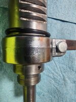
Jim, in regards to the spindle collar, does the slight bevel install towards the quill or towards the spindle pulley?

Please look at the attached pics. I installed the following parts: (starting from the check end, going up)
Feed Stop Bracket
Quill Snap Ring
Quill Bumper O-Ring
At top of quill on spindle shaft:
Steel Washer
O-Ring
Spindle Collar

Does this look correct, and have I left anything out? Buying this DP in boxes and bags didn't give me much reference on how things go, and trying to merge Craftsman diagrams with hybrid parts is a bit confusing.
Thanks for your assistance. (And I may have more questions later!)
Joe
 

Attachments

  • 17150883411873737556616551816995.jpg
    17150883411873737556616551816995.jpg
    837.2 KB · Views: 14
  • 17150883833933269868175043448147.jpg
    17150883833933269868175043448147.jpg
    843.6 KB · Views: 13

FrankLee

Well-known member
Joined
Sep 13, 2010
Messages
3,634
Location
seMI, 48317
Jim, in regards to the spindle collar, does the slight bevel install towards the quill or towards the spindle pulley?

Please look at the attached pics. I installed the following parts: (starting from the check end, going up)
Feed Stop Bracket
Quill Snap Ring
Quill Bumper O-Ring
At top of quill on spindle shaft:
Steel Washer
O-Ring
Spindle Collar

Does this look correct, and have I left anything out? Buying this DP in boxes and bags didn't give me much reference on how things go, and trying to merge Craftsman diagrams with hybrid parts is a bit confusing.
Thanks for your assistance. (And I may have more questions later!)
Joe
Yes, your photos look correct.

Just be sure to tighten the cone of the set screw into the divot in the spindle. This will slightly compress the rubber washer and apply preload to the bearings.
 
OP
S

Slowjoe

Active member
Joined
Dec 3, 2015
Messages
31
Location
Port Clinton, Ohio
Thank you. I now have the quill/spindle assembly installed. Scratching my head on spindle pulley...I see where the small snap ring registers into the groove below the pulley bearing. Where does the large snap ring register?
 

FrankLee

Well-known member
Joined
Sep 13, 2010
Messages
3,634
Location
seMI, 48317
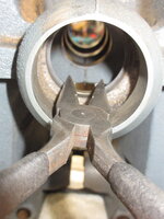
The outer snap ring gets installed in the head casting. The outer race of the lower bearing rests on the snap ring.

You don't have to remove the quill/spindle assembly to install the snap ring. Just lower the quill to get the spindle out of the way. I forgot to install that snap ring on multiple occasions.

img_8507_52338827261_o.jpg img_8508_52338827161_o.jpg
 
Last edited:
OP
S

Slowjoe

Active member
Joined
Dec 3, 2015
Messages
31
Location
Port Clinton, Ohio
Ok, thanks. Now I have to figure out how to get that ring into the head casting. I don't have that long snap ring tool like you showed me.
 

FrankLee

Well-known member
Joined
Sep 13, 2010
Messages
3,634
Location
seMI, 48317
Needle nose pliers work just fine. I believe I filed the hook of that snap ring so needle nose pliers gripped better. Photos added above.

IIRC, those long external snap ring pliers I showed you were for the inner snap ring on the pulley.
 
OP
S

Slowjoe

Active member
Joined
Dec 3, 2015
Messages
31
Location
Port Clinton, Ohio
Oh, ok. I pulled the spindle/quill out again, and I see a groove inside the casting where it registers. I assume I can install it before installing the spindle/quill? Then install the spindle pulley/sleeve/bearing assembly last?
 
OP
S

Slowjoe

Active member
Joined
Dec 3, 2015
Messages
31
Location
Port Clinton, Ohio
Am I correct in placing the bearing right up
against the sleeve? i.e., the sleeve is a spacer to place the bearing in the right location on the pulley shaft?
 

FrankLee

Well-known member
Joined
Sep 13, 2010
Messages
3,634
Location
seMI, 48317
Ok, good.

I assemble the head on my work bench with the head resting on it's back motor mount side.

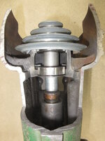
Below is the order in which I assemble the head. All sub-assemblies are first assembled independently.
  1. install the quill/spindle assembly
  2. install the pinion/spring/hub assembly
  3. install the spindle pulley
    The spindle aids in keeping the bearings aligned which make installation easy.
    Confirm that the spindle pulley is fully seated onto the outer snap ring.
  4. install the feed stop assembly
  5. install the chuck
  6. install the feed handles, head trim, badge
 
Last edited:

FrankLee

Well-known member
Joined
Sep 13, 2010
Messages
3,634
Location
seMI, 48317
Am I correct in placing the bearing right up
against the sleeve? i.e., the sleeve is a spacer to place the bearing in the right location on the pulley shaft?
Yes.

install and fully seat the upper bearing onto the pulley shaft
install the bearing spacer
install and fully seat the lower bearing against the spacer
install the inner snap ring

51442835728_4f6f6e2166_b.jpg 51443323094_e47aaff939_k.jpg
 
To avoid these ads, REGISTER NOW!
Top Bottom