To avoid these ads, REGISTER NOW!

Welding in patch panels

MP&C

Well-known member
Joined
Oct 21, 2009
Messages
4,396
Location
Leonardtown, MD
eKqUqAf.jpg

After some grinding and primer

zZ4Y6Qj.jpg


Picture is not showing up...


Hey Robert,
Nice job on fixing the low spot (oil canning) of the hood.
It is amazing what you can do with metal!

So now your using a TIG?
Are you finding it works better than the MIG?


Thanks Don, TIG will give you a softer weld for easier planishing, less weld proud for less clean up (grinding) while still producing a full penetration weld.
 
To avoid these ads, REGISTER NOW!

MP&C

Well-known member
Joined
Oct 21, 2009
Messages
4,396
Location
Leonardtown, MD
Did a guest spot on Manic Mechanic's YouTube channel for some MIG welding 101.


Check out some of their other how-to videos, give them a follow...
 
Last edited:

larry4406

Well-known member
Joined
Jan 27, 2006
Messages
18,963
Location
Northern Virginia
Did a guest spot on Manic Mechanic's YouTube channel for some MIG welding 101.


Check out some of their other how-to videos, give them a follow...

Nice video Robert!
Thanks again for sharing your knowledge and skills and presenting them in simple clear ways.
 

mopar4don

Well-known member
Joined
Mar 9, 2013
Messages
103
Did a guest spot on Manic Mechanic's YouTube channel for some MIG welding 101.


Check out some of their other how-to videos, give them a follow...

Thank you Robert.
Because you took the time to explain the process on this and other threads it has helped a lot!
So I know that video will help! I look forward to more of your teaching
 

NYBODYMAN

Well-known member
Joined
Sep 10, 2013
Messages
4,823
Location
NY
Looking to revive this thread. Need some motivation to get going on our projects as Spring emerges!!
 

MP&C

Well-known member
Joined
Oct 21, 2009
Messages
4,396
Location
Leonardtown, MD
I've got a weld test coming up soon, a gap VS no-gap on two virtually identical panels so we can monitor any difference in the results. Started with two panels stacked and added some low crown on the power hammer, then smoothed them out on the English wheel.


IMG_9087.JPG


Then some profile templates were made so we can monitor any changes...


IMG_9095.JPG


….one for each direction....


IMG_9096.JPG


IMG_9097.JPG


IMG_9098.JPG


IMG_9099.JPG


We'll cut equal sized "patches" out of each, leave a gap with one and the other will be tightly fitted. Both will be welded using MIG. Test coming up in about a week... or so.
 

MP&C

Well-known member
Joined
Oct 21, 2009
Messages
4,396
Location
Leonardtown, MD
Had a comment on another forum that I responded to, and thought the exchange would be right at home here as well.


texasking said:
Makes a lot of sense. Always just tried to make the patch small to limit the area of warpage instead of placing it where I can control the warpage. Thanks for the enlightenment.

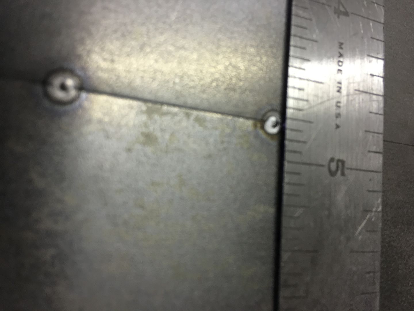
Went back through this thread to see if I had missed anything, and I think we can expand on this comment by TK just a bit, may help with understanding warpage. I had done some test welds a few years back and I think the pictures taken will help out here. The tacks were done using the TIG and NO filler for minimal warpage. This also means we need absolutely tight joints... Here's a video of the tacking process, and as said in video, amperage is set at 70. Based on 18 gauge thickness this should have been about 45, but as we also do with MIG "dot" welding, higher amperage and less elapsed time on trigger pull = flatter welds, less HAZ.


Note minimal weld size, minimal HAZ with the higher amperage, shorter burst...


IMG_1948.jpg


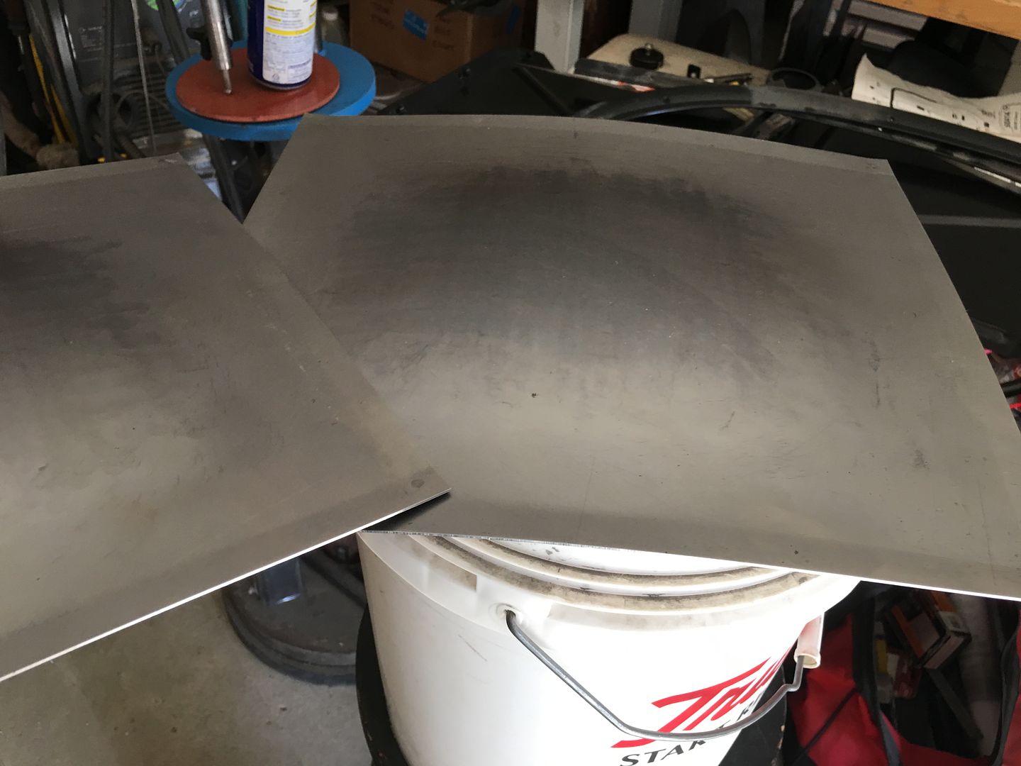
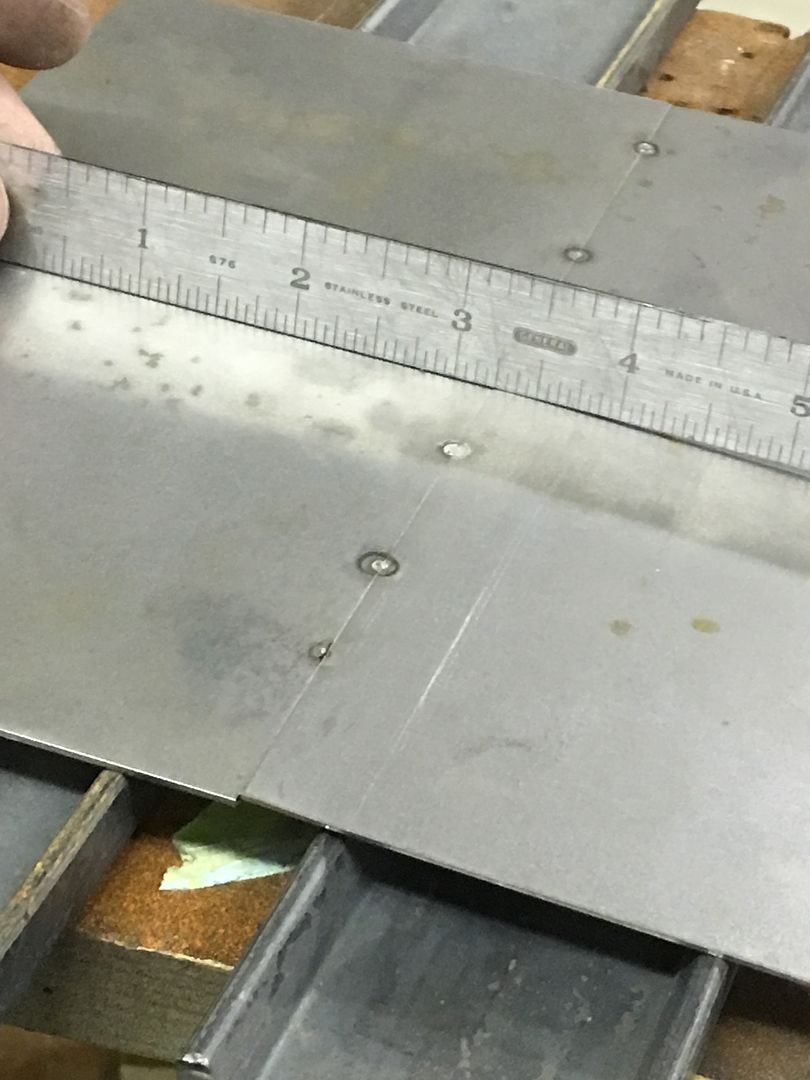
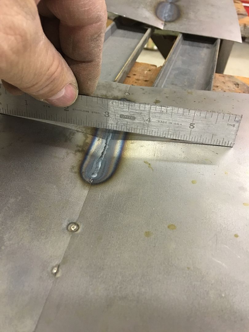
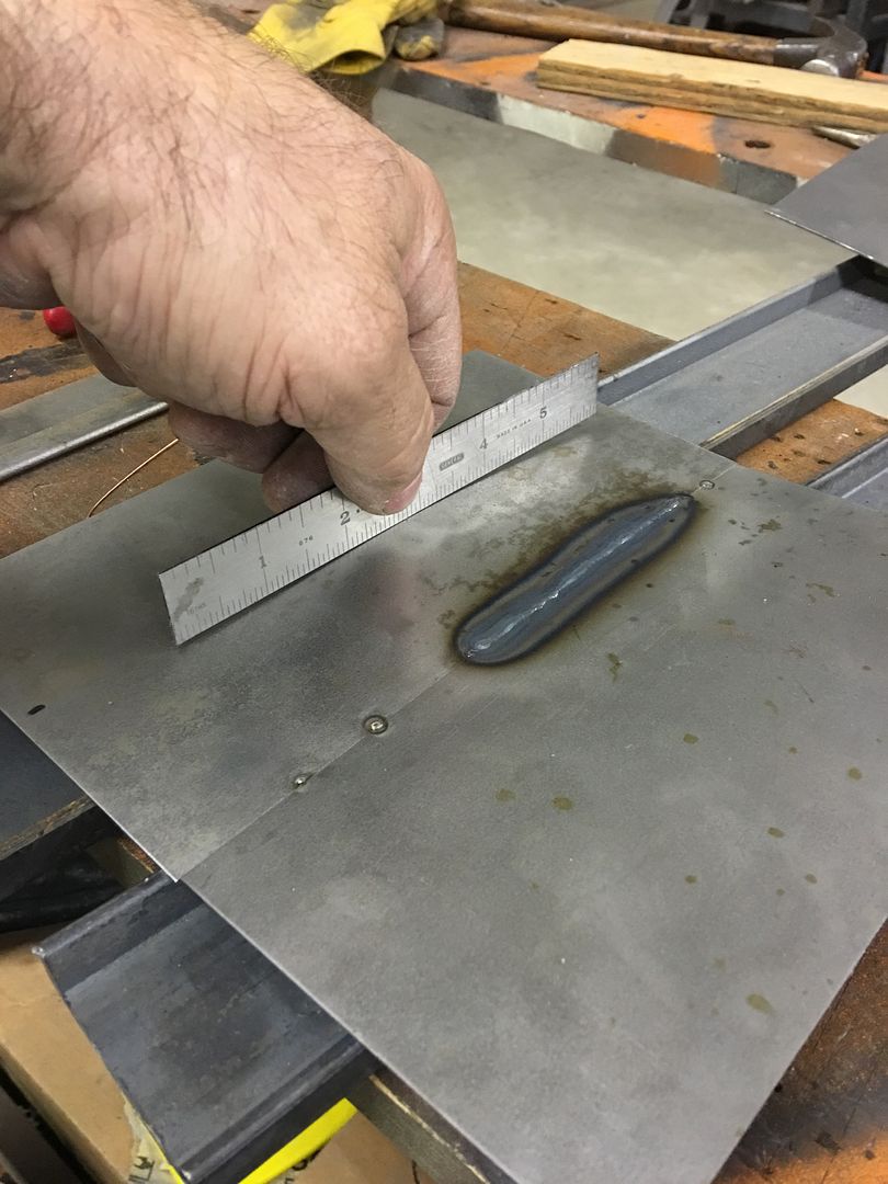
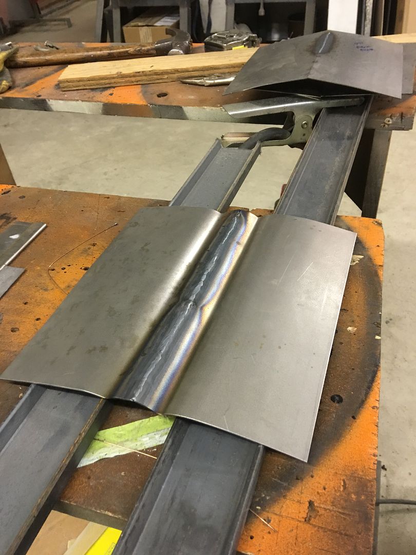
Patches started out flat and for the most part remained so..


IMG_1963.jpg


IMG_1964.jpg


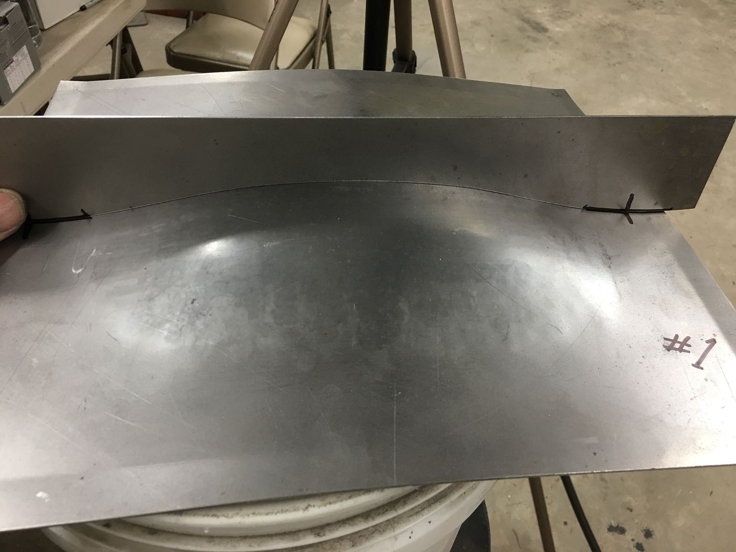
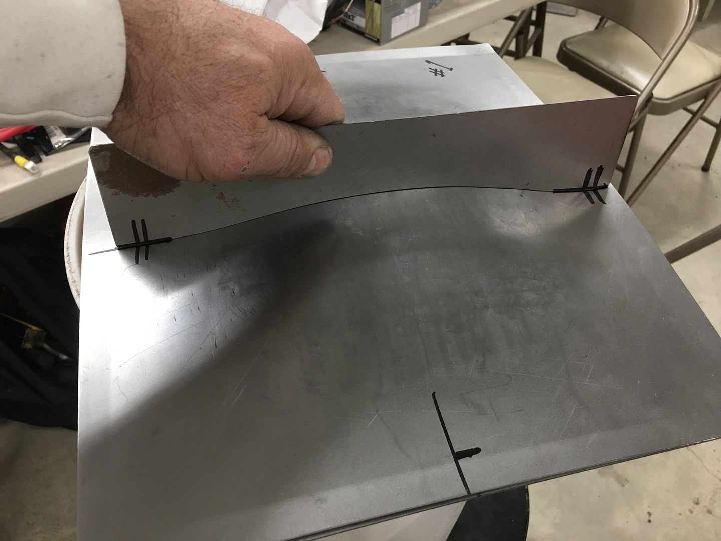
Adding a weld pass we are quick to see some distortion...


IMG_1966.jpg


IMG_1965.jpg


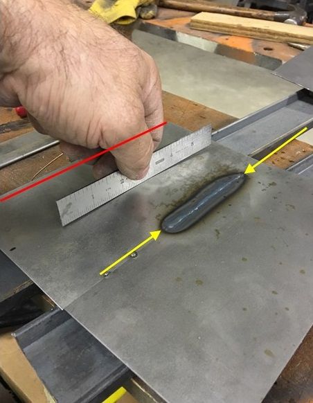
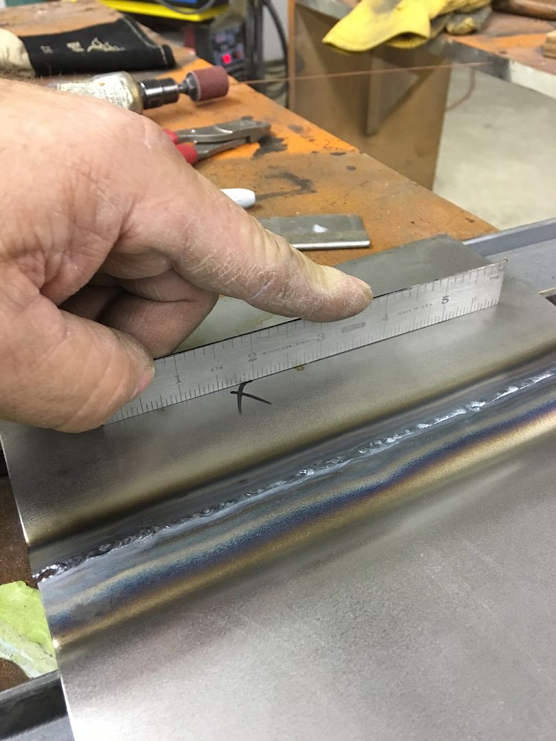
Examining this further, even though we have absolutely tight gaps for less instance of the panels pulling together, we still see distortion.. This is your typical weld shrinkage as the weld cools. Note in the next picture the panel is still fairly flat along the edges (red line), some shrinking at the weld (yellow arrows) and show a dramatic pucker between the two. Note that the weld has yet to be planished, so the weld shrinkage is pulling the metal alongside it together, the areas unaffected by heat remain largely unchanged (red line) and the area between the two are forming a bulge due to these differing forces. Here we address the problem, not the result. Planish out the weld to stretch it in length and the bulge will disappear. Don't make a habit of chasing the result, a shrinking disc on the bulge is not the correct resolution; if this were a crowned panel that action would be causing a severe low area.


IMG_1965A.jpg


Referring back to an earlier statement I made on weld location:

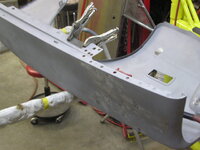
So if given the choice here, I am using the tallest quarter available and putting the seam: 1) where I have access for planishing 2) in a higher crown area to help control warping 3) near body crease to help control warping (keeping enough distance for dolly placement).

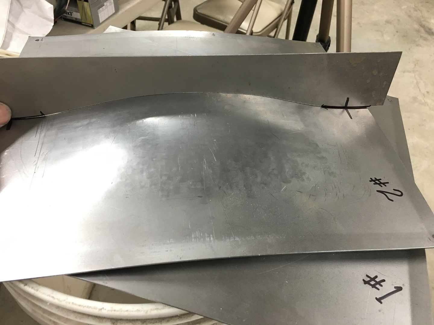
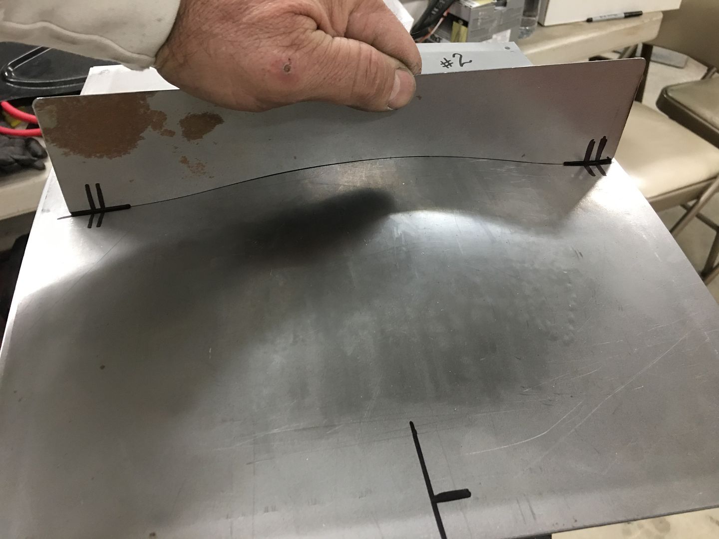
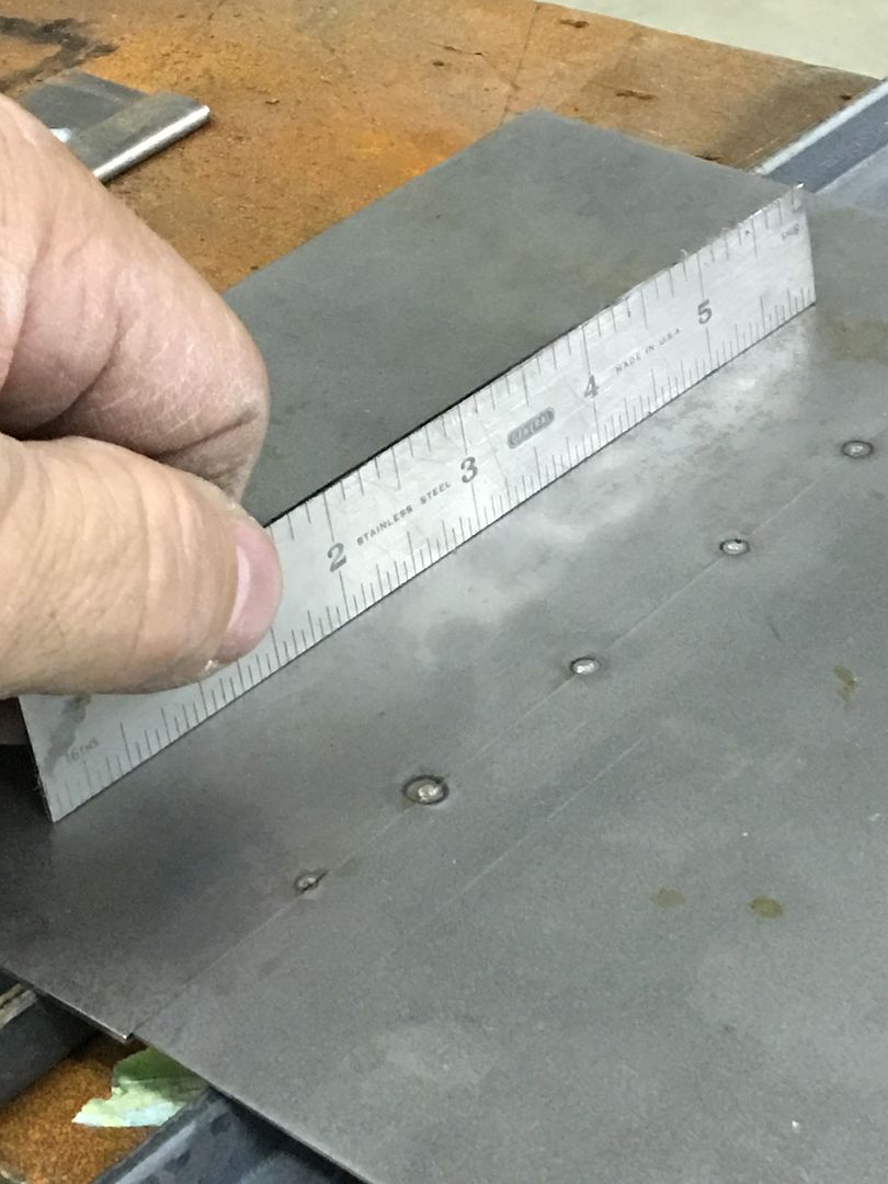
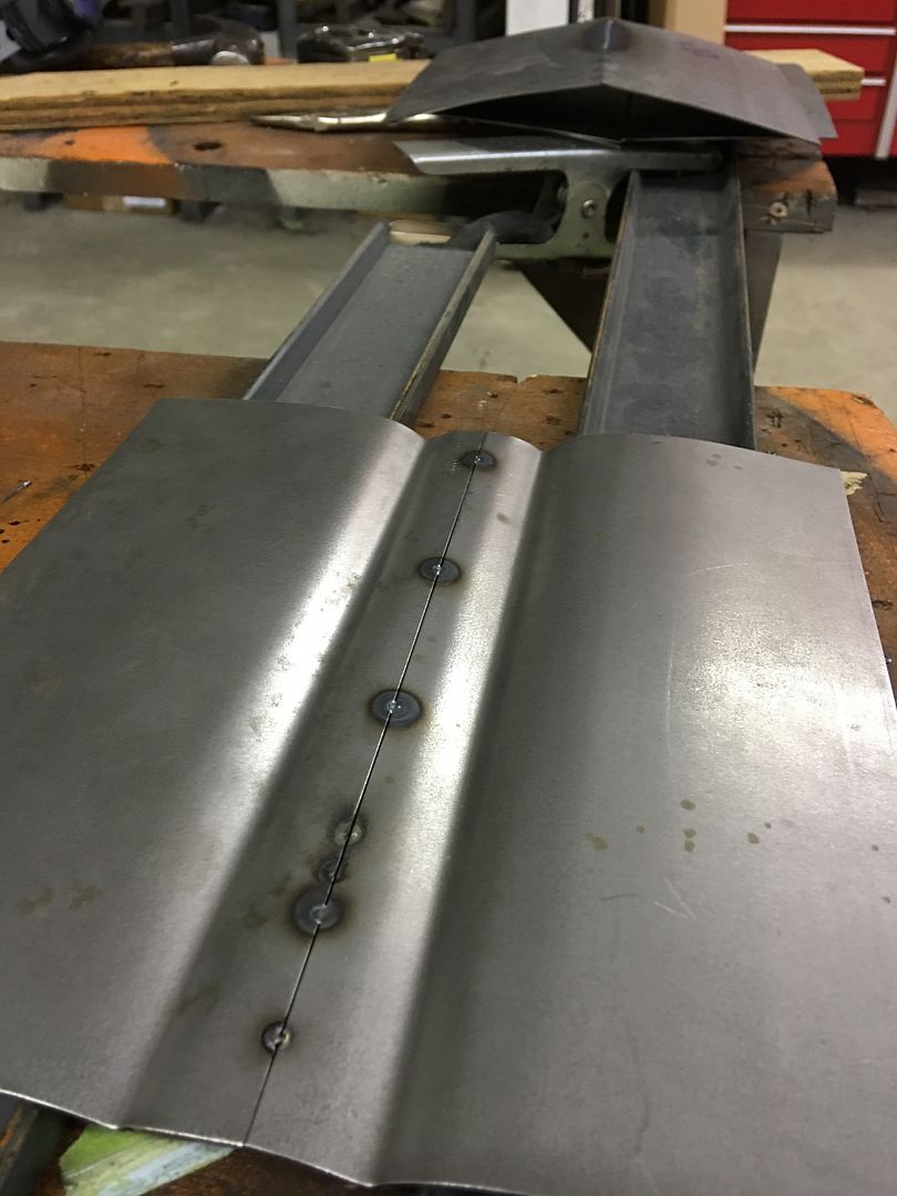
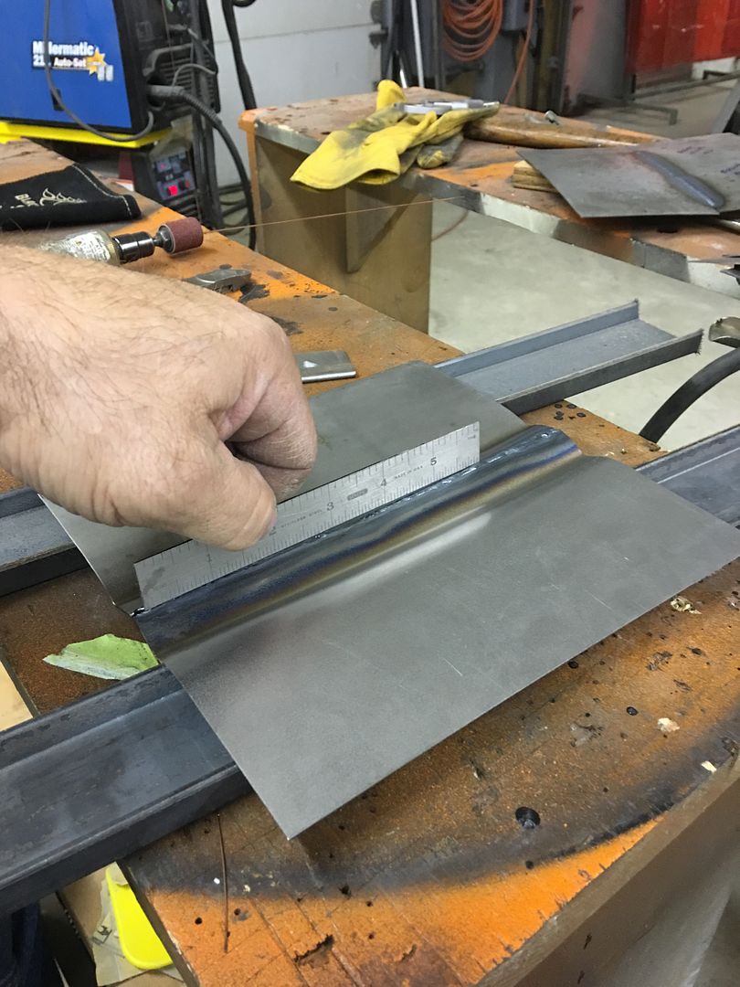
......let's try this same scenario using a crowned sample near a body crease so we can take advantage of all 3 choices...


IMG_1986.jpg


Weld pass....


IMG_1991.jpg


IMG_1999.jpg


IMG_1998.jpg


Here we can see how the weld location and panel features (crown, body crease) helped to control and limit any warping effects. The weld will still need planishing to restore the crown of the center bead, as no doubt it has pulled in slightly, but this is hands down a dramatic improvement over the flat "patches" we did the first time. This shows how these features in your body panels can help out in controlling weld distortion, so take advantage of these in weld location and leave the limiting of panel size as your absolute last consideration.
 

WoodsTruck

Well-known member
Joined
Jan 12, 2013
Messages
1,019
Have you experimented with linear welding versus pulse welding?

I was working on a Toyota last summer with relatively thin sheet metal and found myself pulse welding manually with my MIG. It appeared to have decent penetration and less distortion as a small area got hot then cooled quickly before getting tacked again. Given the thin metal it also minimized my blow through since I was minimizing the heat affected zone.
 

MP&C

Well-known member
Joined
Oct 21, 2009
Messages
4,396
Location
Leonardtown, MD
By pulse welding do you mean successive welds, one after the other? We did do these in that fashion:


Picture177.jpg


Rear side:


Picture178.jpg


You can see where the start and stop took place in the change in the HAZ. This also left a pucker at those spots which was fun to planish out. It was this result that changed my process to singular weld dots. Slower, yes. More consistent results with less puckers also..
 

MP&C

Well-known member
Joined
Oct 21, 2009
Messages
4,396
Location
Leonardtown, MD
I've got a weld test coming up soon, a gap VS no-gap on two virtually identical panels so we can monitor any difference in the results. Started with two panels stacked and added some low crown on the power hammer, then smoothed them out on the English wheel.


IMG_9087.jpg


Then some profile templates were made so we can monitor any changes...


IMG_9095.jpg


….one for each direction....


IMG_9096.jpg


IMG_9097.jpg


IMG_9098.jpg


IMG_9099.jpg


We'll cut equal sized "patches" out of each, leave a gap with one and the other will be tightly fitted. Both will be welded using MIG. Test coming up in about a week... or so.


Well that was a pretty long "or so". We broke out the test panels last night and cut out the "patch panels". The patches are about 4" diameter, the one for test sample one was cut out using a 4" holesaw, then a replacement cut out of another crowned panel we had made to match..


IMG_1300.jpg


IMG_1301.jpg


IMG_1302.jpg


IMG_1303.jpg


IMG_1304.jpg


Sample one will be our tightly fitting patch test sample. Sample two is cut out using an approximate .030 gap, as per the blade thickness on the air body saw. A cut off wheel on the Dremel gives us a starting point.. This sample will follow the "gap" theory. In an attempt to keep weld distortion to a minimum, the weld gap will be maintained. (not my method, just following the technique someone else suggested)

Our hole size is scribed from sample 1. So I didn't follow the lines exactly. Couldn't do coloring books either..


IMG_1305.jpg


IMG_1306.jpg


IMG_1308.jpg


IMG_1307.jpg


IMG_1310.jpg


IMG_1312.jpg


IMG_1313.jpg


IMG_1314.jpg


IMG_1316.jpg


IMG_1317.jpg


IMG_1319.jpg


Although using the TIG or O/A would give us a softer weld and likely a better job than the MIG, most enthusiasts use the point and shoot option of the MIG. So we'll use the MIG so that others can use this as a learning tool, and that we can see how the results pan out between "gap" vs "no-gap"
 

mopar4don

Well-known member
Joined
Mar 9, 2013
Messages
103
I have some issues with a fender and need some advice on how to fix it.
This is a passenger side fender from a 69 Charger.
What I have is an area where the metal is high or proud. I am also getting some oil canning.

take a look at this video
 
Last edited:

mopar4don

Well-known member
Joined
Mar 9, 2013
Messages
103
I messaged Robert about this and I figured I would continue it here so that others might learn. Any and all feedback is appreciated.

Anyway the 1st thing Robert asked was what type of damage was done in that area?
I had to go back through my pics from 6 years ago but found a couple that shows I had filled a few pinholes with weld
 

Attachments

  • P5200045.JPG
    P5200045.JPG
    61.9 KB · Views: 32
  • P5200046.JPG
    P5200046.JPG
    60.7 KB · Views: 32
  • P5290048.JPG
    P5290048.JPG
    63.8 KB · Views: 31
To avoid these ads, REGISTER NOW!

joe49

Well-known member
Joined
Sep 25, 2009
Messages
1,883
Location
Tonica, Il
Are the spots you welded still visable on the under side of the fender? Planishing those spots will releave the shrink, and allow the fender to return to its shape.
 

MP&C

Well-known member
Joined
Oct 21, 2009
Messages
4,396
Location
Leonardtown, MD
Don, the valley that travels from one end to the other, can you lay a straight edge in there to see if it is unaffected or does the bulge creep over into that as well?
 

mopar4don

Well-known member
Joined
Mar 9, 2013
Messages
103
Are the spots you welded still visable on the under side of the fender? Planishing those spots will releave the shrink, and allow the fender to return to its shape.
The weld dots were ground down on the back side, but I should be able to find them.
Don, the valley that travels from one end to the other, can you lay a straight edge in there to see if it is unaffected or does the bulge creep over into that as well?
The bulge is definitely in the valley. But I can get pics tonight.
Is this something where having a shrinking disc would help? If so I will need to get one coming.
Can you recommend one? 4-1/2 inch or 9 inch or both?
 

MP&C

Well-known member
Joined
Oct 21, 2009
Messages
4,396
Location
Leonardtown, MD
The weld dots were ground down on the back side, but I should be able to find them.

The bulge is definitely in the valley. But I can get pics tonight.
Is this something where having a shrinking disc would help? If so I will need to get one coming.
Can you recommend one? 4-1/2 inch or 9 inch or both?
I'd hold off on that for now....
 

MP&C

Well-known member
Joined
Oct 21, 2009
Messages
4,396
Location
Leonardtown, MD
Looking at a screen shot of the top of the fender from your video, it appears someone got too happy in planishing any deformity from the welding shown in pictures above. Are these marks indeed from planishing??


98DD1EC4-D80C-4AE7-882C-B7B056008A51.jpeg
 

mopar4don

Well-known member
Joined
Mar 9, 2013
Messages
103
the shiny marks in the paint are from me trying to hammer dolly it. I didnt do very much as I was not making any progress
 

mopar4don

Well-known member
Joined
Mar 9, 2013
Messages
103
ok checking in the valley, and if I put one end of my 24 inch straight edge on top of the raised area (where my hand is) it is farily flat.
it should be a slow curve from one end to the other. Like you said
20220329_185843.jpg
 
Last edited:

mopar4don

Well-known member
Joined
Mar 9, 2013
Messages
103
these 3 pics are all the same.
I never moved the straight edge, just took 3 pics, an overall, a left side, and a right side.

20220329_182137.jpg

20220329_182156.jpg
20220329_182202.jpg
 
Last edited:

MP&C

Well-known member
Joined
Oct 21, 2009
Messages
4,396
Location
Leonardtown, MD
Don, watch this video, and see if you can do the same...it will allow the ruler to more closely follow the contour to better show the defects.. One down through the valley, and from there, one a couple inches towards the inside, one a couple inches towards the outside. You may need to employ the assistance of a camera operator as you will need two hands...


Last edited:

mopar4don

Well-known member
Joined
Mar 9, 2013
Messages
103
Don, watch this video, and see if you can do the same...it will allow the ruler to more closely follow the contour to better show the defects.. One down through the valley, and from there, one a couple inches towards the inside, one a couple inches towards the outside. You may need to employ the assistance of a camera operator as you will need two hands...
HI Robert, I borrowed a flexible straight edge from work and shot a couple of videos for you.
One thing to note. The valley is not parallel. AS you start at the back of the fender the valley is about 3 inches from the hood.
As you move twards the front of the car the valley gradually moves to about 5 inches from the hood this being at the front of the car or fender. So It has a double curve if that makes any sense.

these 3 short videos explain the valley


Last edited:

mopar4don

Well-known member
Joined
Mar 9, 2013
Messages
103
And a video with the flexible straight edge.
I hope this helps. And thank you for your help!

 
Last edited:

MP&C

Well-known member
Joined
Oct 21, 2009
Messages
4,396
Location
Leonardtown, MD
Don, just for comparison, grab a reading on the opposite fender with your ruler. Always good to have something to compare to..

Any welding is going to shrink so we would expect that shrinkage in the proud areas (slight crown on either side of the valley) would pull that downward into a low. Any shrinking of the valley should pull that upward into less of a valley. Given the extremely tight oil can (which in most cases indicates a stretch) and the bulge in the crowned area my gut feeling is to leave the valley alone until the very end, any highs there may likely be pulled along from the stretch you have in the crown. Back to the "spot" welds that you did to fill in holes?, they should have only required minimal planishing, only on the weld dots, to restore the panel to it's original form. What it looks like now is that far too much planishing was done.

A crowned panel is an ideal candidate for using the donut dolly for shrinking, that would be my go-to method in this case. A few hits on the donut dolly and you should almost immediately see the tight oil can start to loosen...
 

mopar4don

Well-known member
Joined
Mar 9, 2013
Messages
103
Don, just for comparison, grab a reading on the opposite fender with your ruler. Always good to have something to compare to..

Any welding is going to shrink so we would expect that shrinkage in the proud areas (slight crown on either side of the valley) would pull that downward into a low. Any shrinking of the valley should pull that upward into less of a valley. Given the extremely tight oil can (which in most cases indicates a stretch) and the bulge in the crowned area my gut feeling is to leave the valley alone until the very end, any highs there may likely be pulled along from the stretch you have in the crown. Back to the "spot" welds that you did to fill in holes?, they should have only required minimal planishing, only on the weld dots, to restore the panel to it's original form. What it looks like now is that far too much planishing was done.

A crowned panel is an ideal candidate for using the donut dolly for shrinking, that would be my go-to method in this case. A few hits on the donut dolly and you should almost immediately see the tight oil can start to loosen...
Thanks Robert, I will post another video of the opposite fender.
I know you have a donut dolly tutorial on here. Can you direct me to it?
I found info on page 1 and on page 12 of this thread.
 

mopar4don

Well-known member
Joined
Mar 9, 2013
Messages
103
As promised, here is a video showing the good fender that I am using for comparison.


mopar4don

Well-known member
Joined
Mar 9, 2013
Messages
103
So I started shrinking with the donut dolly and after approx. 20 hits the oil can will now stay down. From this point do I need to push the oil can center spot back down and concentrate my hits in the center, or work the dolly around the center, hitting the high spots?


part1

part2
 
To avoid these ads, REGISTER NOW!
Top Bottom