How do you handle removal... Like what if you take this engine out or have to swap in another? Taking those soldered splices out seems difficult to impossible.I have not seen those before Cam, although they do look cool. Sorry I opened that can of worms, just passionate about some things I guess and what works and has worked for me for decades, doesn't necessarily make it an industry standard and others may choose a different route. I agree about never soldering at a connection due to weight and causing fatigue cracking/breaking of the wire from bouncing around the rigid termination, never been a fan of that and always make my connections back away from the termination and keep them as small as possible. I'm sure you do this as well but I also don't make multiple splices in the same area in a loom. I stagger them up and down the loom based on how many wires I'm splicing in to keep the loom diameter consistant. It bugs me seeing a bunch of connections (**** or solder) in one small section of a loom. Seeing a big bulge in a loom is annoying. Unfortunately in the Jeep or off-road world I see it all too much from people adding in lights and/or other accessories but for some reason they feel they have to tap in all in the same place, so a 3/4" loom has a 2" bulge in the middle.
I had to laugh at the last picture showing the Scotchlok though. I hate those damn things and started twitching when I saw it.[emoji38]_hitti

You are using an out of date browser. It may not display this or other websites correctly.
You should upgrade or use an alternative browser.
You should upgrade or use an alternative browser.
ZMotorsports Shop Projects 2.0
- Thread starter zmotorsports
- Start date

OP
zmotorsports
ALLIANCE MEMBER
How do you handle removal... Like what if you take this engine out or have to swap in another? Taking those soldered splices out seems difficult to impossible.
If all I'm doing is removing the engine, it is all plugged into OEM connectors and will simply unplug. There should be no reason to have to unsolder the connections.
polexican23
Banned
Since you are using a Camaro SS fan, does that not give you the ability to label this a Jeep Wrangler SS?
Bob Heine
ALLIANCE MEMBER
Mike, I try hard to enjoy wiring. OK, I try hard to not hate wiring. I use your method of splicing into bundles mainly because it stays together before I start soldering. It's always in a remote location where I can't get the bundle out to a convenient place to work.
I prefer soldered joints but have used **** connectors in emergencies. For decades I've used crimped end terminals but because of my cheap crimping tools the connectors would fall off. Not every time but often enough. The cheap crimper I used would require two or three crimps, one for the wire and one for the insulation but if I missed the insulation crimp, a third crimp further up the barrel. Over the decades as I rose out of abject poverty, I bought better crimp tools.
When Weatherpak connectors showed up, I was really screwed. If I managed to get the tiny crimp on the conductor, the insulation crimp would mess up and damage the wire. I ended up buying an expensive crimper just for those Weatherpak connectors (it makes both crimps at the same time). Then I bought a Pertronix crimper that handles all the connectors, including the non-insulated terminals I crimp and then solder those and then shrinkwrap them. In my desk-jockey world that was a lot of money for crimpers but now I can successfully crimp and solder terminals.

I prefer soldered joints but have used **** connectors in emergencies. For decades I've used crimped end terminals but because of my cheap crimping tools the connectors would fall off. Not every time but often enough. The cheap crimper I used would require two or three crimps, one for the wire and one for the insulation but if I missed the insulation crimp, a third crimp further up the barrel. Over the decades as I rose out of abject poverty, I bought better crimp tools.
When Weatherpak connectors showed up, I was really screwed. If I managed to get the tiny crimp on the conductor, the insulation crimp would mess up and damage the wire. I ended up buying an expensive crimper just for those Weatherpak connectors (it makes both crimps at the same time). Then I bought a Pertronix crimper that handles all the connectors, including the non-insulated terminals I crimp and then solder those and then shrinkwrap them. In my desk-jockey world that was a lot of money for crimpers but now I can successfully crimp and solder terminals.
Attachments

Rogers954
Well-known member
Love that view of the mountains!
Oh man scrolling though checking out the pictures and I see this!!! I knew immediately where this was without checking out the op's location. I'm in Clearfield right on the border of Syracuse.....small world
C2tuck
Well-known member
I’m sure you will be very pleased with your tire choice. Heard nothing but good things about them from the F-250/350 crowds I run in, and they all love them. I put AT2’s on mine as they didn’t have those in the size I needed and I absolutely love them. They aren’t loud and after 10k miles still look brand new.
Sent from my iPhone using Tapatalk
Sent from my iPhone using Tapatalk
OP
zmotorsports
ALLIANCE MEMBER
I have to say, the first half of this project sailed by but the last little bit with all the tedious details feels like I’m moving at a snails pace. I really am working diligently on it despite what the pictures say.
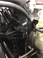
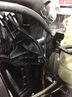
Ran the power, ground and signal wires for the electric fan. Again I put the wires in an abrasion proof sleeve and ran it under the power steering reservoir over to the battery and the signal wire around the front over to the ECM. I used an Adel clamp to secure the loom to the fan shroud.
The ECM and power distribution board mounted after completing the A/C lines and pushing the interior wire loom through the firewall.

Getting closer.

As for engine bay I think all that is remaining is connecting my power steering cooler lines and mounting the coolant surge tank then filling with coolant.
I then have to move inside and pull my gauge cluster to tie in for the CAN network and mount my GM accelerator pedal. I also have my accessory wires along the firewall to tidy up and put into split loom but that’s not necessary to start the engine.
Thanks for looking.
Ran the power, ground and signal wires for the electric fan. Again I put the wires in an abrasion proof sleeve and ran it under the power steering reservoir over to the battery and the signal wire around the front over to the ECM. I used an Adel clamp to secure the loom to the fan shroud.
The ECM and power distribution board mounted after completing the A/C lines and pushing the interior wire loom through the firewall.
Getting closer.
As for engine bay I think all that is remaining is connecting my power steering cooler lines and mounting the coolant surge tank then filling with coolant.
I then have to move inside and pull my gauge cluster to tie in for the CAN network and mount my GM accelerator pedal. I also have my accessory wires along the firewall to tidy up and put into split loom but that’s not necessary to start the engine.
Thanks for looking.
Attachments


Last edited:
OP
zmotorsports
ALLIANCE MEMBER
Since you are using a Camaro SS fan, does that not give you the ability to label this a Jeep Wrangler SS?
I hadn't thought about that but I like it. Wrangler SS.

Last edited:
OP
zmotorsports
ALLIANCE MEMBER
Mike, I try hard to enjoy wiring. OK, I try hard to not hate wiring. I use your method of splicing into bundles mainly because it stays together before I start soldering. It's always in a remote location where I can't get the bundle out to a convenient place to work.
I prefer soldered joints but have used **** connectors in emergencies. For decades I've used crimped end terminals but because of my cheap crimping tools the connectors would fall off. Not every time but often enough. The cheap crimper I used would require two or three crimps, one for the wire and one for the insulation but if I missed the insulation crimp, a third crimp further up the barrel. Over the decades as I rose out of abject poverty, I bought better crimp tools.
When Weatherpak connectors showed up, I was really screwed. If I managed to get the tiny crimp on the conductor, the insulation crimp would mess up and damage the wire. I ended up buying an expensive crimper just for those Weatherpak connectors (it makes both crimps at the same time). Then I bought a Pertronix crimper that handles all the connectors, including the non-insulated terminals I crimp and then solder those and then shrinkwrap them. In my desk-jockey world that was a lot of money for crimpers but now I can successfully crimp and solder terminals.
That is very nice crimper Bob. I like that it does all. I have separate crimpers for the standard insulated or non-insulated then a separate one for the Weatherpack connectors, another of for the Doetsch style barrel connectors found on Harley's. One that did all would be nice.
OP
zmotorsports
ALLIANCE MEMBER
Oh man scrolling though checking out the pictures and I see this!!! I knew immediately where this was without checking out the op's location. I'm in Clearfield right on the border of Syracuse.....small world
Yes it is a small world. My wife and I just moved 2-years ago from West Point which is even closer to where you are at. Clearfield area has been my stomping grounds for the past 26 years, we moved to West Point in 1991 and left in December 2016.
OP
zmotorsports
ALLIANCE MEMBER
I’m sure you will be very pleased with your tire choice. Heard nothing but good things about them from the F-250/350 crowds I run in, and they all love them. I put AT2’s on mine as they didn’t have those in the size I needed and I absolutely love them. They aren’t loud and after 10k miles still look brand new.
Sent from my iPhone using Tapatalk
That is good to hear as I was back and forth between another set of KO2's and the new Ridge Grapplers but everything I had read and heard led me to try the Nitto's.
Thanks for the feedback.
Closer by the day Mike, exciting stuff! How much drama is there going to be mounting the go pedal. I seem to remember the DBW assembly mother mopar uses is oddly shaped and it wasn't much fun doing a WOT switch mount to them. But then again that was the car stuff so maybe the jeep is more squared off and not so damn whoopsy.
OP
zmotorsports
ALLIANCE MEMBER
Closer by the day Mike, exciting stuff! How much drama is there going to be mounting the go pedal. I seem to remember the DBW assembly mother mopar uses is oddly shaped and it wasn't much fun doing a WOT switch mount to them. But then again that was the car stuff so maybe the jeep is more squared off and not so damn whoopsy.
To be perfectly honest Cam, I hadn't spent a lot of time looking at the pedal. What I've seen others do is use the Jeep accelerator pedal and then modify the program in the operating system to recognize the Jeep inputs but I want to stay pure GM so I opted for the GM pedal. When I first looked about 6 months or so ago I remember thinking it shouldn't be too difficult to just fabricate a small adapter bracket. To be honest that upper pedal mounting bolt looks like it will be the hardest to get to. I will also have to cut the Jeep pedal apart and use the switches because that is how the oil life monitor is reset through the Chrysler BCM. I think I will just piggyback the OEM pedal on top of the GM pedal mounting merely for resetting the oil life monitor but again, I will know more as I dig deeper into the interior wiring. Probably just a standoff bracket and sandwich the GM pedal between the firewall mount and the Jeep pedal is what I am envisioning.
Speaking of wiring, I really only have four wires to solder into the gauge cluster. I have to cut them in splice in the CAN bridge so the GM and Chrysler systems can talk and that is done at the back of the gauge cluster. Then I have a pedal connector and the ALDL connector that I will mount where the Jeep one is now and tie the OEM one up where it is still easily accessible for everything other than the engine performance system.
Lastly I have a small two wire connector for shifting gears when in the manual gate, tapshift. These wires will plugs into the CAN bridge and then I have to locate a spot to install the toggle switch where it is within easy reach for my tapshift feature. I've seen other mount their on the left side of the steering column so they can easily reach it with their left hand and bump gears up or down when in the manual gate on the shifter. I am left handed and drive with my left hand so I have been playing around with locations that feel natural to me and I think I have a nice spot just above my right knee below the radio and to the side of the column where it feels very natural for me to reach and switch gears when manually shifting. Technically this will be about the only thing of the swap that won't feel or look OE. If I wanted to spend another several hundred dollars I could install a 2012 or newer console and shifter. I would have to send it to Motech and have them work it over to work like a factory bumpshift but communicate with the GM operating system but that was a bit more expense than I see beneficial so to me having a small toggle switch on the dash for manual shifting off-road is not a big deal at all and only cost me a $8.00 switch. I have friends that actually don't care for the bumpshifter in the 2012+ Jeeps because bouncing around offroad they say they bump the gearshift when they don't want to and it shifts so it's probably six of one, half a dozen of another on whether it is a worthwhile modification or not so I'll just use a small switch on the dash, although the new shifter would definitely stay with the whole OE theme.
Sounds like they use the same assembly as the cars and you are correct, the two top nuts aren't the easiest things to get at. As for the shifting there used to be (and probably still is) a retrofit kit that was a standard Mercedes paddle shifter set up we installed on the cars. It came with everything to mount to the wheel but most importantly a new clock spring assemble with the additional wiring that was dedicated to the manual shift controls. I know just the clock spring part can be bought separately but no idea if it would fit your column. However it would sure make it look factory. For the Nag1 trans the manual shift feature only took 3 wires, it was a very simple deal to add paddle shifters as far as wiring goes.
Last edited:
OP
zmotorsports
ALLIANCE MEMBER
Sounds like they use the same assembly as the cars and you are correct, the two top nuts aren't the easiest things to get at. As for the shifting there used to be (and probably still is) a retrofit kit that was a standard Mercedes paddle shifter set up we installed on the cars. It came with everything to mount to the wheel but most importantly a new clock spring assemble with the additional wiring that was dedicated to the manual shift controls. I know just the clock spring part can be bought separately but no idea if it would fit your column. However it would sure make it look factory. For the Nag1 trans the manual shift feature only took 3 wires, it was a very simple deal to add paddle shifters as far as wiring goes.
Thanks Cam but I'm not a fan of paddle shifters in an off-road application. With the steering wheel spinning around both directions from lock to lock my pea brain won't be able to keep track of which way is up and which ways is down so I'll stick with a simple toggle switch that I can understand.

Thanks Cam but I'm not a fan of paddle shifters in an off-road application. With the steering wheel spinning around both directions from lock to lock my pea brain won't be able to keep track of which way is up and which ways is down so I'll stick with a simple toggle switch that I can understand.
I'm not a fan either. I guess my point was the clock spring solution for the addition wiring. Maybe I should have left it at that huh?
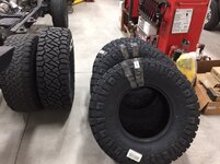
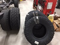
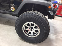
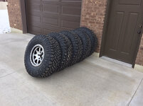
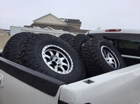
A little more progress was made, but first, look what finally arrived today. I ordered these on a Black Friday sale and they were back ordered until now.
37x12.50x17 Nitto Ridge Grapplers. They will be mounted on my new Raceline Avenger 17x9 wheels.
Thanks for looking.


Mike, I think you will love the Nitto's. I've had a set of these on my Jeep for almost 2 years now, one of the best off road tires I've ever used. Extremely smooth and quiet running and very good off road. Excellent choice. Great job on the up grade so far.
Attachments


TimeWarpF100
Well-known member
Curb weight shouldn't change much from before, unfortunately my Jeep is quite heavy @ 6k pounds. This engine/transmission combination is only about 40 pounds heavier than the original 3.8 liter engine and 4-speed auto trans. When I set it down the other night and measured my ride height there was no change from before I started the project.
The 3.8 must have felt anemic in a 6000 lb jeep. My last jeep could not have been much more than 2000 lbs. (yep it's been a while) (CJ2A)
Even with 400 HP that is still a lot of weight to push around. I had no idea a jeep would be over 4000 lbs.
Waiting to see your jeep on the road.
My Current eco swap had engine in place and running in a couple days. Now it will take 5yrs to get it on road . .
OP
zmotorsports
ALLIANCE MEMBER
I'm not a fan either. I guess my point was the clock spring solution for the addition wiring. Maybe I should have left it at that huh?
Gotcha Cam. In all honesty, the tapswitch wiring is about the easiest item to complete of the entire swap so no big deal just wiring in a simple momentary switch for the tapshift feature to function properly, but thanks for tossing ideas out.
OP
zmotorsports
ALLIANCE MEMBER
Mike, I think you will love the Nitto's. I've had a set of these on my Jeep for almost 2 years now, one of the best off road tires I've ever used. Extremely smooth and quiet running and very good off road. Excellent choice. Great job on the up grade so far.
Good to hear Dan. I read a lot about their road manners and how quiet they are on pavement so I hope I know what to expect there but I am really just as anxious to get them off-road and test them out.
Glad to hear you've been happy with them.
OP
zmotorsports
ALLIANCE MEMBER
The 3.8 must have felt anemic in a 6000 lb jeep. My last jeep could not have been much more than 2000 lbs. (yep it's been a while) (CJ2A)
Even with 400 HP that is still a lot of weight to push around. I had no idea a jeep would be over 4000 lbs.
Waiting to see your jeep on the road.
My Current eco swap had engine in place and running in a couple days. Now it will take 5yrs to get it on road . .
Yeah, in stock form it was over 4800 pounds before I even started modifying it. Last time I weighed it I was about 5960 without me in it so even with 400+ HP it is a lot of weight to have to move.
The 3.8 liter did a "fair" job hauling it around once I regeared to 5.38:1. With the stock 4.10's it was a turd and the past couple weeks of driving it around with the 4.56's it wasn't much better as OD is pretty much useless and it struggles merging with freeway traffic. All I am trying to do with this swap is bring the drivability back as well as the fun factor. I realize it isn't going to be a hot rod and that's not what I am expecting.
If I can get it up and running this weekend I figure it will be a two week upgrade but several of those days I did absolutely nothing on it and only have had a few hours each night. I have been keeping pretty decent notes on how long I work on it each day so when I am done I will add everything up. I haven't looked at the total lately but I would guess I am somewhere around 30 hours by now total in the engine swap.
Thanks again for stopping by and checking out the progress. I've enjoyed following along on your projects, you seem to have the wiring portion of engine swaps down to a science.
Last edited:
Bigblue&Goldie
Well-known member
Mike another idea for the pedal is to just use the OEM Jeep pedal so you can keep those switches and ergonomics in tact and mount the GM pedal up in the firewall with a lever attaching it to the OEM Jeep pedal. We run a similar setup on an Ecotec fly by wire setup as the GM electronics are the best, but the physical pedal wouldn't withstand our foot smashing it in the rough stuff. In our case, we use a fabricated metal pedal tied via linkage to the GM pedal. Sounds ghetto, but a lot of high end offroad cars are done this way in order to keep the GM electronics.
OP
zmotorsports
ALLIANCE MEMBER
Mike another idea for the pedal is to just use the OEM Jeep pedal so you can keep those switches and ergonomics in tact and mount the GM pedal up in the firewall with a lever attaching it to the OEM Jeep pedal. We run a similar setup on an Ecotec fly by wire setup as the GM electronics are the best, but the physical pedal wouldn't withstand our foot smashing it in the rough stuff. In our case, we use a fabricated metal pedal tied via linkage to the GM pedal. Sounds ghetto, but a lot of high end offroad cars are done this way in order to keep the GM electronics.
Thanks, I'll look at that but I really have it in my head that I want to use the GM pedal pure and then just cut the Jeep pedal down for resetting the oil life monitor and I'm a bit hard headed so that is what I am going to try to incorporate. That may change as I progress but will know more once I spend a bit more time investigating.
OP
zmotorsports
ALLIANCE MEMBER
Didn’t get as much done as I had hoped tonight. Arrived home to have my neighbor practically waiting on my doorstep to take a look at his generator. He and his wife recently purchased a new to them coach and they are new to RV’ing so I’ve been tutoring him and assisting his for the past several months. They are getting ready to head south for a month or so and his generator wouldn’t power his coach so I ended up helping him for a bit.
Once I did get back to my shop and on the Jeep I was able to get some more wiring completed in the engine bay and get it ran through split loom around the brake booster as well as my accessory wiring across the firewall. I think the wiring in the engine bay is really coming together nicely.


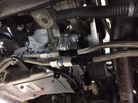
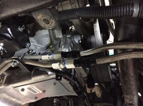
On my way home today I stopped by my local hydraulic supply house and picked up a couple of adapters to go from the 1/2” tubing on the GM transmission lines to my -6 JIC hose ends on my transmission cooler.


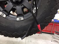
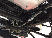
While I had the Jeep up in the air I filled the transfer case with fluid and then before I lowered it back to the ground I dressed the winch cables in abrasion casing and heat shrink then snaked them under the core support and up along the right fender to the battery tray.

Still have a lot of work remaining and I didn’t even get a chance to look inside at the interior wiring tonight.
Thanks for looking.
Once I did get back to my shop and on the Jeep I was able to get some more wiring completed in the engine bay and get it ran through split loom around the brake booster as well as my accessory wiring across the firewall. I think the wiring in the engine bay is really coming together nicely.
On my way home today I stopped by my local hydraulic supply house and picked up a couple of adapters to go from the 1/2” tubing on the GM transmission lines to my -6 JIC hose ends on my transmission cooler.
While I had the Jeep up in the air I filled the transfer case with fluid and then before I lowered it back to the ground I dressed the winch cables in abrasion casing and heat shrink then snaked them under the core support and up along the right fender to the battery tray.
Still have a lot of work remaining and I didn’t even get a chance to look inside at the interior wiring tonight.
Thanks for looking.
Attachments
-
 231600bf3f6ff08fca1f49d49145fbf5.jpg823.5 KB · Views: 0
 -
 d46a135895953bd281dde3ed5cb6014c.jpg751.6 KB · Views: 0
 -
 aae20f38cee1ac41b35a3a74222b4902.jpg850.9 KB · Views: 0
 -
 939bca4232099718ffceb9ee771fa4cc.jpg709.4 KB · Views: 0
 -
 bee398f74748cca83aa5050c4cf759db.jpg690.4 KB · Views: 0
 -
 947d2d431e07981704c55fdcaa1c6c26.jpg706.2 KB · Views: 0
 -
 ab27324b0c411804a5863fd871b44641.jpg761.5 KB · Views: 0
Last edited:
C2tuck
Well-known member
That is good to hear as I was back and forth between another set of KO2's and the new Ridge Grapplers but everything I had read and heard led me to try the Nitto's.
Thanks for the feedback.
Oh. And they don’t throw stones like the BFG’s. That was one of my biggest problems with them...Picturing what my rocker panels look like after pulling onto the pavement and getting up to speed while hearing the rocks fly[emoji35]
Sent from my iPhone using Tapatalk
Ohmthis
Well-known member
Mike, I’m really liking the attention to detail on this swap. Being an electrician I love seeing nice neat wire runs that are also “hidden in plain sight”. I never would have thought that your Jeep would be so heavy. I might have guessed 4500 lbs or so. Your vision is taking shape buddy, can’t wait to see it finished.
Ole Slewfoot
Well-known member
Can you have both without an idle validation freakout and dead pedal?Thanks, I'll look at that but I really have it in my head that I want to use the GM pedal pure and then just cut the Jeep pedal down for resetting the oil life monitor and I'm a bit hard headed so that is what I am going to try to incorporate. That may change as I progress but will know more once I spend a bit more time investigating.
OP
zmotorsports
ALLIANCE MEMBER
Mike, I’m really liking the attention to detail on this swap. Being an electrician I love seeing nice neat wire runs that are also “hidden in plain sight”. I never would have thought that your Jeep would be so heavy. I might have guessed 4500 lbs or so. Your vision is taking shape buddy, can’t wait to see it finished.
Thank you, I appreciate the compliments. I like the way the wiring is turning out myself. I had the accessory wiring in split loom before but it was in about four smaller sizes as I had added lights and accessories at different times. I prefer having them in a single common loom paralleling the OEM loom as it looks so much cleaner.
I am even quite pleased with the engine wiring and by using all OEM GM harness and the way it lays on the engine it looks like it belongs there. The most difficult part if hiding the wiring in plain sight was making the large GM trunk lay down and look neat and tidy on the left fender area near both the OEM Chrysler PCM and now the GM ECM as that is a busy area.
Thanks again for following along and commenting.
OP
zmotorsports
ALLIANCE MEMBER
Can you have both without an idle validation freakout and dead pedal?
I should have no issues as the Jeep pedal is only communicating with the Chrysler BCM for the purpose of oil monitor reset. The GM performance system is only looking at the GM pedal and neither signals should really recognize the other.
Thanks for checking in on the project.
JCQuick
Well-known member
Mike, I try hard to enjoy wiring. OK, I try hard to not hate wiring. I use your method of splicing into bundles mainly because it stays together before I start soldering. It's always in a remote location where I can't get the bundle out to a convenient place to work.
I prefer soldered joints but have used **** connectors in emergencies. For decades I've used crimped end terminals but because of my cheap crimping tools the connectors would fall off. Not every time but often enough. The cheap crimper I used would require two or three crimps, one for the wire and one for the insulation but if I missed the insulation crimp, a third crimp further up the barrel. Over the decades as I rose out of abject poverty, I bought better crimp tools.
When Weatherpak connectors showed up, I was really screwed. If I managed to get the tiny crimp on the conductor, the insulation crimp would mess up and damage the wire. I ended up buying an expensive crimper just for those Weatherpak connectors (it makes both crimps at the same time). Then I bought a Pertronix crimper that handles all the connectors, including the non-insulated terminals I crimp and then solder those and then shrinkwrap them. In my desk-jockey world that was a lot of money for crimpers but now I can successfully crimp and solder terminals.
Bob I'm sending you a PM on that . Now back to Mikes thread
Oh. And they don’t throw stones like the BFG’s. That was one of my biggest problems with them...Picturing what my rocker panels look like after pulling onto the pavement and getting up to speed while hearing the rocks fly[emoji35]
Sent from my iPhone using Tapatalk
I live on a gravel driveway and you're correct, they don't pickup rocks at all.
Ohmthis
Well-known member
Mike, I try hard to enjoy wiring. OK, I try hard to not hate wiring. I use your method of splicing into bundles mainly because it stays together before I start soldering. It's always in a remote location where I can't get the bundle out to a convenient place to work.
I prefer soldered joints but have used **** connectors in emergencies. For decades I've used crimped end terminals but because of my cheap crimping tools the connectors would fall off. Not every time but often enough. The cheap crimper I used would require two or three crimps, one for the wire and one for the insulation but if I missed the insulation crimp, a third crimp further up the barrel. Over the decades as I rose out of abject poverty, I bought better crimp tools.
When Weatherpak connectors showed up, I was really screwed. If I managed to get the tiny crimp on the conductor, the insulation crimp would mess up and damage the wire. I ended up buying an expensive crimper just for those Weatherpak connectors (it makes both crimps at the same time). Then I bought a Pertronix crimper that handles all the connectors, including the non-insulated terminals I crimp and then solder those and then shrinkwrap them. In my desk-jockey world that was a lot of money for crimpers but now I can successfully crimp and solder terminals.
Bob, I wholeheartedly believe this is the biggest reason why a soldered joint is better in my opinion. I , like mike am from the industrial maintenance background and I’ve seen too many issues with crimped connections. Most of the time the correct crimp tool would have made a usable joint. It does **** with buying several crimp tools to do the job, but c’est la vie!
OP
zmotorsports
ALLIANCE MEMBER
WooHoo. SUCCESS!!!!
She runs.
A long day of knocking items off of my list but she runs.
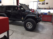
But before I get to the details some teaser shots of the new tires & wheels. I dropped off my new 37” Nitto Ridge Grapplers and my new Raceline Avenger wheels at my local tire shop this morning and about and hour later went back and picked them up. Evidently it was a slow morning as I wasn’t expecting the call so soon telling me they were done.
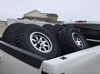
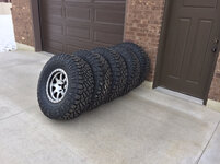
I think they will look awesome and provide the ole girl with just a little cosmetic face lift plus another inch or so of ground clearance.
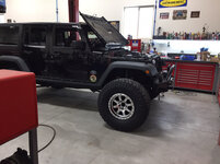

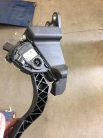
Here is my new GM accelerator pedal.

Now here’s according to my wife my first “senior moment”. She said she can tell me that now that I’m 50-years old.
Anyway, while I was waiting for my tires to be mounted I was wandering around the shop enjoying my morning coffee and decided to gather up some boxes from parts and put a couple of piles together of parts that I’m going to discard and some that still have value and I may be able to sell or give away. While I was moving parts around I found a bubble wrapped part that I didn’t remember seeing before and definitely didn’t remember ordering.

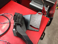
Upon cutting it open I found a powder coated metal bracket with a couple of elongated slots and a couple of bends. Wouldn’t ya know it, this was an accelerator pedal bracket from Motech that I definitely don’t remember ordering but yet it was sitting on my workbench in the slowly shrinking pile of parts. This is a very nice bracket and pretty much exactly what I was thinking of fabricating but I probably wouldn’t have been able to build such a nice bracket.
Here’s my new GM accelerator bolted to the bracket ready for installation.
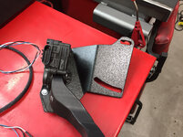
Here is my Chrysler pedal after cutting the arm off and ready to reinstall.

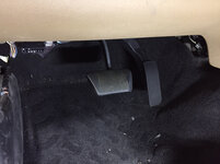
The GM pedal for normal accelerating duties and the Chrysler pedal for resetting my oil life monitor.

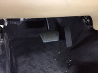
Bolted in place. I’m not gonna lie, that upper bolt was a ***** to get the nut installed. Between being high up on the firewall and trying to squeeze my big *** up under the dash it was a PITA to say the least. I couldn’t get both hands up there at the same time which complicated reinstallation of the pedal and bracket.

Here is the MoCAN module that is basically the bridge between the GM and Chrysler CAN networks. This is during the wiring process and running of the interior wires and plugging into the CAN bridge. One connection goes to the back of the gauge cluster where I need to make four solder connections. Also plugged into the CAN bridge is the new ALDL or data link connector. Lastly there are two wires from the CAN bridge to my tap shift switch for the transmission.
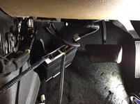
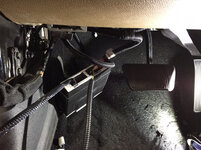
CAN bridge mounted to an aluminum brace under the dash where it nearly looks factory.

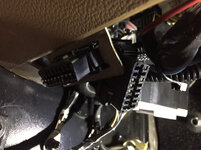
The GM data link connector that will be used for engine performance now resides in the bracket and the Chrysler data link connector that will be used for the remainder of the chassis such as ABS is zip-tied alongside but within easy access.

Below dash items completed.
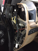
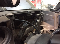
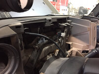
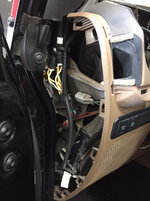
Now moving up to the top of the dash. Running the wiring up the side towards the gauge cluster.
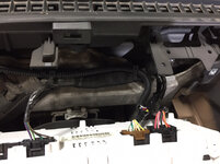
Gauge cluster removed and wires at the ready to make the solder connections.
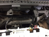
Wires soldered and heat shrunk.

Wire loom taped back up and ready to plug the gauge cluster back in.

Connectors plugged back into the cluster.
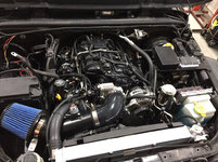
With the interior connections all made I moved back to the engine bay to finish up the cooling system and install my surge tank and add coolant.


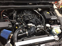
Intake duct, air filter and MAF sensor installed. I also added transmission fluid.
At this point I threw the battery in and cycled the ignition a few times, bled the air from the fuel rail then cycled ignition a few more times until I got fuel. This should minimize cranking time and promote a faster start.
Sure enough, she only cranked over a few revolutions and fired right up with nearly instant oil pressure.
That pretty much wraps it up for the evening. A little more wiring of my accessories and install my Aeroforce gauge then I can move on to exhaust and driveshaft installation.
Thanks for looking.
She runs.
A long day of knocking items off of my list but she runs.
But before I get to the details some teaser shots of the new tires & wheels. I dropped off my new 37” Nitto Ridge Grapplers and my new Raceline Avenger wheels at my local tire shop this morning and about and hour later went back and picked them up. Evidently it was a slow morning as I wasn’t expecting the call so soon telling me they were done.
I think they will look awesome and provide the ole girl with just a little cosmetic face lift plus another inch or so of ground clearance.
Here is my new GM accelerator pedal.
Now here’s according to my wife my first “senior moment”. She said she can tell me that now that I’m 50-years old.
Anyway, while I was waiting for my tires to be mounted I was wandering around the shop enjoying my morning coffee and decided to gather up some boxes from parts and put a couple of piles together of parts that I’m going to discard and some that still have value and I may be able to sell or give away. While I was moving parts around I found a bubble wrapped part that I didn’t remember seeing before and definitely didn’t remember ordering.
Upon cutting it open I found a powder coated metal bracket with a couple of elongated slots and a couple of bends. Wouldn’t ya know it, this was an accelerator pedal bracket from Motech that I definitely don’t remember ordering but yet it was sitting on my workbench in the slowly shrinking pile of parts. This is a very nice bracket and pretty much exactly what I was thinking of fabricating but I probably wouldn’t have been able to build such a nice bracket.
Here’s my new GM accelerator bolted to the bracket ready for installation.
Here is my Chrysler pedal after cutting the arm off and ready to reinstall.
The GM pedal for normal accelerating duties and the Chrysler pedal for resetting my oil life monitor.
Bolted in place. I’m not gonna lie, that upper bolt was a ***** to get the nut installed. Between being high up on the firewall and trying to squeeze my big *** up under the dash it was a PITA to say the least. I couldn’t get both hands up there at the same time which complicated reinstallation of the pedal and bracket.
Here is the MoCAN module that is basically the bridge between the GM and Chrysler CAN networks. This is during the wiring process and running of the interior wires and plugging into the CAN bridge. One connection goes to the back of the gauge cluster where I need to make four solder connections. Also plugged into the CAN bridge is the new ALDL or data link connector. Lastly there are two wires from the CAN bridge to my tap shift switch for the transmission.
CAN bridge mounted to an aluminum brace under the dash where it nearly looks factory.
The GM data link connector that will be used for engine performance now resides in the bracket and the Chrysler data link connector that will be used for the remainder of the chassis such as ABS is zip-tied alongside but within easy access.
Below dash items completed.
Now moving up to the top of the dash. Running the wiring up the side towards the gauge cluster.
Gauge cluster removed and wires at the ready to make the solder connections.
Wires soldered and heat shrunk.
Wire loom taped back up and ready to plug the gauge cluster back in.
Connectors plugged back into the cluster.
With the interior connections all made I moved back to the engine bay to finish up the cooling system and install my surge tank and add coolant.
Intake duct, air filter and MAF sensor installed. I also added transmission fluid.
At this point I threw the battery in and cycled the ignition a few times, bled the air from the fuel rail then cycled ignition a few more times until I got fuel. This should minimize cranking time and promote a faster start.
Sure enough, she only cranked over a few revolutions and fired right up with nearly instant oil pressure.
That pretty much wraps it up for the evening. A little more wiring of my accessories and install my Aeroforce gauge then I can move on to exhaust and driveshaft installation.
Thanks for looking.
Attachments
-
 13a4e3e7385b75d8d0febc09dacb9be5.jpg731.6 KB · Views: 0
 -
 d62fcf74ae8cb357db8b375afee6447a.jpg678.8 KB · Views: 0
 -
 3c8e2bcf270a5eb1f6b34037f53348a4.jpg806.4 KB · Views: 0
 -
 1940fe41c038cb964ee451ed9aae0e51.jpg700.2 KB · Views: 0
 -
 960cd52b0255cfa1e18205eb5731eb4e.jpg722.7 KB · Views: 0
 -
 e24f878a02a8bf1be6d4e15e013cd022.jpg707.9 KB · Views: 0
 -
 435f346093d091a5d5beae523cd1b61c.jpg677.5 KB · Views: 0
 -
 5b3628a488b4dff8ef28167d817e57c0.jpg695.7 KB · Views: 0
 -
 44ed4913a4569492aff424b2b6c325bc.jpg627.5 KB · Views: 0
 -
 7798e73c1b902ff7b3d34ab3e19b7bc4.jpg800.9 KB · Views: 0
 -
 a93a24169d54d7322fe51f9ad19e7b3a.jpg830.3 KB · Views: 0
 -
 a73e8aca4eda5e7ba4aeece8e11c23d5.jpg765.8 KB · Views: 0
 -
 fd5b6ea0d5a84d26e2bc30ad9f49a45a.jpg831.6 KB · Views: 0
 -
 30634519f27f8015b89017b7dfd4b286.jpg752.5 KB · Views: 0
 -
 d57d342e57dec34fa440e017cbd2efbc.jpg770.4 KB · Views: 0
 -
 633694f6548de84a7826dbbd01cfcfac.jpg656.1 KB · Views: 0
 -
 25d2c47ef059cf1ed0d2a36da6ceceec.jpg809 KB · Views: 0
 -
 5138cf3e1bc2e18eac2ef43b6abdc36f.jpg711.3 KB · Views: 0
 -
 9f9d3bcc90aef865fa3bfc0efc2fca02.jpg737.1 KB · Views: 0
 -
 2266684993bbd05ce10aa0945b9e40b6.jpg738 KB · Views: 0
 -
 99f5e41838ba4e644bca82bc0fa3b2dd.jpg725.4 KB · Views: 0
 -
 eee00f5c7ff5b0090b12ec3eda33f641.jpg808.1 KB · Views: 1
Last edited:
Finallygotit
ALLIANCE MEMBER
Congratulations Mike, that's awesome!! 
larry4406
Well-known member
Amazing!
I assume you retained the AC? Do you charge that yourself or farm out?
I assume you retained the AC? Do you charge that yourself or farm out?
Duker
Well-known member
Great news Mike! So where will her first maiden voyage be?
Sent from my iPad using Tapatalk Pro
Sent from my iPad using Tapatalk Pro
Bigblue&Goldie
Well-known member
Wow! Record time on the swap! The wheels look fantastic!
OP
zmotorsports
ALLIANCE MEMBER
Congratulations Mike, that's awesome!!
Thanks Dan.