To avoid these ads, REGISTER NOW!

Above 1200 Sq/FT The Action Sports Garage

Wokspaces above 1200 squarefeet.
OP
G

Grant Gunderson

Well-known member
Joined
May 17, 2013
Messages
2,325
Location
Bellingham, WA
I’m sure you said where you got those machine guards from at the time, but if you remember and how efficient are they at containing chips flying everywhere? Your shop is so compact I’m sure that is a very high concern of yours. I’m still getting my Ex-Cell-O mill set up and am worried about chip control. Thanks, and keep going, I learn stuff every time I visit your shop!
https://moffattproducts.com/flex-mounted-shields/

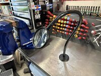
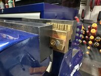
The Sheilds work great. They are not 100% effective but do drastically help maintain the chip mess. Just wish I would have bought them sooner. I most likely will make a vacuums extractor holder for the mill at somepoint too. The lights on the mill are from them as well. I also have this magnifier glass from them as well.
IMG_6680.jpeg

All of their products are well made. And made in the usa too. Just not cheap.
 

Attachments

  • image.jpg
    image.jpg
    672.7 KB · Views: 21
To avoid these ads, REGISTER NOW!

SilverJimmy

Well-known member
Joined
Apr 14, 2012
Messages
1,643
Location
Prescott/Flagstaff, AZ
I was a Snap-On dealer for 30 years and every time one of my customers would tell me that my competitor’s tools were cheaper I’d always agree with them, and then point out that they also cost less too! I don’t mind paying more for great quality, especially to the original innovator of that product. How many and what size do you recommend for a 9”x42” mill like mine? I also want to get the slot covers to keep chips from hiding in there too!
 
OP
G

Grant Gunderson

Well-known member
Joined
May 17, 2013
Messages
2,325
Location
Bellingham, WA
I was a Snap-On dealer for 30 years and every time one of my customers would tell me that my competitor’s tools were cheaper I’d always agree with them, and then point out that they also cost less too! I don’t mind paying more for great quality, especially to the original innovator of that product. How many and what size do you recommend for a 9”x42” mill like mine? I also want to get the slot covers to keep chips from hiding in there too!
Mine are 12x12 and I’m happy with that size.
I’m not happy with the slot covers I got from grizzly. I need to either make some custom covers or most likely just cut some urethane strips to fit once I finish the rotary table.
 
OP
G

Grant Gunderson

Well-known member
Joined
May 17, 2013
Messages
2,325
Location
Bellingham, WA
Back to a little work on bikes. My friend was complaining on our last ride how her fork felt super stiff. So I told her I'd take a look at it.

IMG_6684.jpeg
When I pulled the lowers, I noticed the foam ring has a giant chunk missing out of it. She just had a full service done on this bike at a local shop a month ago..... talk about **** work. Only way this happens is if the foam ring isn't properly installed with a seal driver. With the seals out, I tested the fit of the lowers on the stanctions. It was dam sticky and felt very grabby. Something isn't right with the bushings and this is a new fork this year.
IMG_6691.jpeg
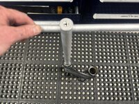
So out comes my Fork Burnshing tool. The various heads burnish the glide bushings in the fork. In realty it basically just speeds up the fork break in process, and cleans up any issues with the bushings being a bit out of tolerance.
IMG_6690.jpeg
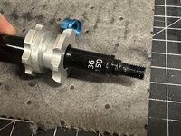
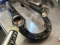
The the 36 size head on for her fox 36, I ran the tool in and out of each leg while twisting it. Took about 5 passes on each leg to get both the upper and lower bushing to the point the tool would easily pass through.
IMG_6692.jpeg
I then added some slickolem to each of the 4 bushings.
IMG_6685.jpeg
I like to keep a full assortment of spare parts for forks on hand. It saves a trip to the local bike shop and is really nice when working on bikes in the evening.
IMG_6696.jpeg
I always use forceps to soak the new rings in the proper bath oil for each leg. These should be well lubricated.
IMG_6697.jpeg
The abby seal press does a great job of quickly and perfectly installing the new seals and foam ring each time.
IMG_6699.jpeg
When I went to reinstall her wheel, I noticed some excessive wear on the caliper. Those black marks are the inner lamination of the rotor. It was that far worn!
IMG_6704.jpeg
The minimum thickness is 1.5mm, she wore it all the way down to 1.25!
IMG_6683.jpeg
I was surprised she still had pad material left, I thought that she must have worn into the backer, but nope, its minimal, but there still pads in there. So tossed some new pads in and upgraded her 180 to a 203 rotor.
 
OP
G

Grant Gunderson

Well-known member
Joined
May 17, 2013
Messages
2,325
Location
Bellingham, WA
IMG_6726.jpeg
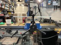
I’ve finally had enough with taking the Kurt handle on and off the vise
IMG_6727.jpeg
So ordered a new made in the USA handle off of eBay for $40. Seems well made. I intend to leave it on the vise so it needs a way to secure it in place. So I’m going to add two set screws to it
IMG_6717.jpeg
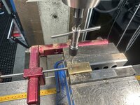
I figured out where the flats are in two spots on different axis. First step is to use a small center drill for the pilot hole since this is a sloped and convex location
IMG_6719.jpeg
Then drilled it with a #7 drill
IMG_6725.jpeg
Followed by a counter sink
IMG_6722.jpeg
Since it’s a through hole I taped it with a ¼-20 gun tap. The gun taps are designed to push the chips through the hole so are less likely to break and cut better than a standard hardware store tap
IMG_6729.jpeg
To secure the handles I’m using vibratight. It works better than the standard blue lock tight imop.
IMG_6730.jpeg
I’m going to use ¼-20 brass set screws so I don’t mar the surface of the vise screw
IMG_6731.jpeg
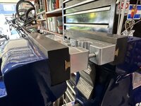
You can see the opposing angles for the set screws here
IMG_6733.jpeg
All installed and rock solid. Plus it clears the y axis handle unlike the Kurt vise handle. I’m happy with it.
 
OP
G

Grant Gunderson

Well-known member
Joined
May 17, 2013
Messages
2,325
Location
Bellingham, WA
I need to add dove tails to a few of my Fox and Rockshocks factory shaft clamps. Some of these won’t work to machine the dovetails into. On others I think it will simply just be easier to add them on VS machine then into.

So I machined some dovetails into some extra brass stock.

IMG_6742.jpeg
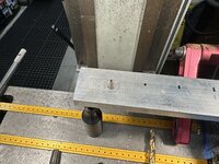
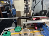
I’m going to use a bone saw AKA a slitting saw to cut the dovetail from the stock material.
IMG_6744.jpeg
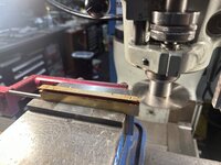
Slitting saws scare me. From this pic I’m sure you can’t imagine why..
IMG_6748.jpeg
IMG_6754.jpeg
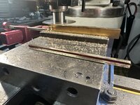
However it’s an efficient way to remove material and you get a pretty good quality finish too.
Here the dovetail has been removed from the stock
IMG_6757.jpeg
I then use the skirting saw to cut the flange from the factory shaft clamps.
IMG_6758.jpeg
I’ll save the drops in case I find a use for them latter. I keep all of my scraps, all thread , rods etc organized by size in old safe deposit boxes.
IMG_6760.jpeg
The arbor for the slitting saw tightened its self stupid tight while cutting. My new copper soft jaws where great for loosening it.
IMG_6761.jpeg
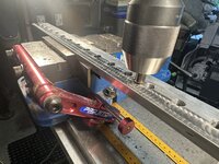
I then milled the edges of the factory clamps smooth as possible since they are a sliding portion of the dovetail system. Btw my new vise handle on the mill sure speeds things up !
IMG_6763.jpeg
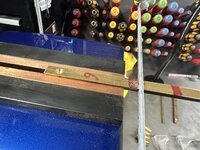
I colored the brass dovetail sections with red sharpie then used a scribe against the shaft clamp to score a line at the precise length needed.
IMG_6764.jpeg
The scribe line was great to get the hacksaw cut started. I then finished each cut with a file to get it to exact size.
 
OP
G

Grant Gunderson

Well-known member
Joined
May 17, 2013
Messages
2,325
Location
Bellingham, WA
IMG_6765.jpeg
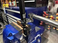
The dovetail pieces then need to get through drilled with a 3mm drill then countersunk. Since I’m going to use metric fasteners the countersink is a 90 degree angle . I’m using my small abrecht chuck for this. It grips these small drills way better.
IMG_6766.jpeg
I used the fine quill feed to make sure I don’t snap the 3mm bit.
IMG_6771.jpeg
The shaft clamps then get blind drilled and tapped. With these small taps using a tap guide in the quill is essential.
IMG_6772.jpeg
Notice how the spiral flutter bottom cutting tap pulls the chips up out of the hole. Thus not only helps prevent the tiny tap from breaking but also allows it to cut better
IMG_6773.jpeg
A little green thread locker and I can assemble the dovetails to the shaft clamps. Here I’m setting up the brass rockshock reverb clamps.
IMG_6779.jpeg
This is a Fox factory clamp with the dovetail added.
IMG_6778.jpeg
IMG_6780.jpeg
Notice how the ball detents I added perfectly align the shaft clamps to the edge of the vise. The guide pins in the shaft clamps further ensure the close square to the shaft.
 
OP
G

Grant Gunderson

Well-known member
Joined
May 17, 2013
Messages
2,325
Location
Bellingham, WA
I picked up this digital Milton inflator years ago. I love it. It’s dead accurate

IMG_7739.jpeg
Plus it uses interchangeable inflator heads such as Presta and Schrader

IMG_6781.jpeg
The problem is storing the heads as I always seem to be using different ones. So plan is to make a storage rack for them using some scrape aluminum bar and some Milton air couplings
IMG_6782.jpeg
The air couplings use a ¼”NPT thread. Since pipe threads are tapered you can’t just drill and tap, you need to also use a tappered pipe reamer.
IMG_6783.jpeg
First I drill the clearance hole.
IMG_6784.jpeg
I then ream the hole so it is tapered to match the pipe thread. Notice how I’m using a tap guide and downward pressure from the quil to aid in cutting.
IMG_6787.jpeg
The hole can then be tapped. I then repeat for all of the holes.
IMG_6788.jpeg
Machine jacks allowed me to clamp the center of the bar and then machine all of the holes without having to reclamp.
IMG_6790.jpeg
I then decided to give it an engine turned finish. A small piece of cratex abrasive in a drill chuck worked great. One full rotation of the x feed handle for each downward press of the quill. Sounds like a lot of work but it went really fast!
IMG_6791.jpeg
All ready for the Milton M type connectors.
IMG_6793.jpeg
A standard ¾ wrench was too thick so my 18mm Snapon low torque got the job done.
 
OP
G

Grant Gunderson

Well-known member
Joined
May 17, 2013
Messages
2,325
Location
Bellingham, WA
Some days are better than others.

2011283704.jpeg
I was notified this morning that I won the action category of Outside magazines photo contest
To capture this shot we started ski touring a few hours before dawn and crossed our fingers we would be created to an amazing sunrise as the previous nights storm pushed out. So it’s really nice to see the hard work pay off

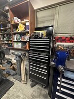
Then I just so happened to see a 40” wide 14. Drawer Lista cabinet pop up for sale for a reasonable price. So I drove down to Lynwood this evening to pick it up.
IMG_6803.jpeg
It basically took up the entire bed of my Super Duty. I also sold my Anvil this week along with my old vise and welding table a little while ago. Ended up making enough on that set of deals to end up with my Wilton 3C for not only no money into it, but cash positive enough to pay for the Lista too. Can’t complain about that!
IMG_6804.jpeg
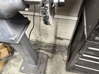
The plan is to put it where my old Craftsman stack is. I bought the Craftsman stack back in Highschool and it’s served me well and is still in great shape but I need more tool storage. So most likely will end up selling it off. Not sure where to move the Baldor too. Thinking I need some sort of mobile base for it. It makes such a damn mess I’d prefer to run it outside if I can find a good way to easily roll it in and out of the shop.
IMG_6809.jpeg
Case in point. Dust from the Baldor is all over the area behind it.
IMG_6817.jpeg
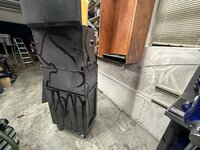
The back of the tool chest is filthy from the buffer dust! I cleaned it and the wall up. Also wiped down the wood cabinet. It will have to get moved higher up the wall. At somepoint I need to build new cabinets better suited to my storage time, but I have too many projects going on right now as it is!
IMG_6810.jpeg
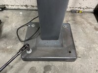
I had secured the buffer to the floor with wedge anchors so it didn’t walk while I was using it.
IMG_6812.jpeg
I must have over tightened this one when I installed it. It pulled up the concrete.
IMG_6815.jpeg
Knowing more now, next time I would have used wedge nuts and not wedge anchor bolts. I need to grind the remaining ones off. Hopefully I can get the new Lista moved into place tomorrow or the next day. Then I need to figure out how I’m going to redo my tool storage layout.
 

merkyworks

Well-known member
Joined
Nov 11, 2016
Messages
587
Location
Texas
Was that pull through from over tightening or the hole not being deep enough? Pic can be deceiving but that anchor looks kind of shallow.
 

SilverJimmy

Well-known member
Joined
Apr 14, 2012
Messages
1,643
Location
Prescott/Flagstaff, AZ
I was facing the same dilemma about the mess my buffer made. Here is my solution, I’m sure you’ll do something vastly more elegant!
08AFEAFF-F78B-4765-8310-144EE4751219.jpeg
5C8071E8-3779-4CFC-BB7A-CE8F8BDE2C02.jpeg
99B70135-D483-4757-9F1F-BEC24D4F61EB.jpeg
A high school friend of mine makes roadside billboard signs, the monster ones 60 feet high you can see for miles! So I got a 1 1/2” x 24” round drop from a sign base and welded it to a cheap two wheel cart, then bolted my Baldor stand to the drop. Ran a piece of 1x2 steel tube as a brace to the handle to stop flex and it’s a handy place to wrap the cord. When I want to make a big mess shining something up I just roll it out the door and start buffing. Works great, coulda used some bigger wheels to make moving it easier, but it’s been like this for over 25 years! Now I’m just gonna sit back and take the shame of how I should have done it if I wasn’t such a hack!
 
OP
G

Grant Gunderson

Well-known member
Joined
May 17, 2013
Messages
2,325
Location
Bellingham, WA
I was facing the same dilemma about the mess my buffer made. Here is my solution, I’m sure you’ll do something vastly more elegant!
08AFEAFF-F78B-4765-8310-144EE4751219.jpeg
5C8071E8-3779-4CFC-BB7A-CE8F8BDE2C02.jpeg
99B70135-D483-4757-9F1F-BEC24D4F61EB.jpeg
A high school friend of mine makes roadside billboard signs, the monster ones 60 feet high you can see for miles! So I got a 1 1/2” x 24” round drop from a sign base and welded it to a cheap two wheel cart, then bolted my Baldor stand to the drop. Ran a piece of 1x2 steel tube as a brace to the handle to stop flex and it’s a handy place to wrap the cord. When I want to make a big mess shining something up I just roll it out the door and start buffing. Works great, coulda used some bigger wheels to make moving it easier, but it’s been like this for over 25 years! Now I’m just gonna sit back and take the shame of how I should have done it if I wasn’t such a hack!
That’s exactly along the lines of what I’ve been thinking! Well done.
 

SilverJimmy

Well-known member
Joined
Apr 14, 2012
Messages
1,643
Location
Prescott/Flagstaff, AZ
The only thing I really wish I had done differently was how I welded the two wheel cart to the round drop. Because I just laid the plate on top of the cart foot/shoe (what is that actually called?!) and welded it together, the plate doesn’t sit flush on the ground. It doesn’t wobble or rock while in use, it’s just that I did it down and dirty to start using it immediately. I should have trimmed the shoe to fit the plate or welded the uprights directly to the plate eliminating the shoe. But it works! I‘m excited to see your interpretation of my hack job and seeing what color you paint it, Baldor gray or that amazing blue you seem fond of!
 

Augus7us

Well-known member
Joined
Jan 14, 2017
Messages
1,190
Location
Central Ohio
IMG_5846.jpeg
To finish his education in power mechanics for the day I took him to see the monster trucks.
IMG_5883.jpeg
Ponied up for the monster truck ride for him too. Ws worth every cent of the $10 to see how excited he was.
As a halloween aficionado I like your boy's shirt!

The second pick I had to scroll back because I thought he was growing a mustache. Made me laugh.

Man you are doing some killer stuff in your shop. The vice turned out great and it was fun to follow along. (y)
 
OP
G

Grant Gunderson

Well-known member
Joined
May 17, 2013
Messages
2,325
Location
Bellingham, WA
As a halloween aficionado I like your boy's shirt!

The second pick I had to scroll back because I thought he was growing a mustache. Made me laugh.

Man you are doing some killer stuff in your shop. The vice turned out great and it was fun to follow along. (y)
Thanks! He’s only 6, but I have a feeling it’s going to feel like a blink of an eye and he will have facial hair!

Screenshot 2023-09-13 at 10.07.16 AM.png
Found out this am that I landed the cover of Ski Canada’s buyers guide.
IMG_6826.jpeg
Unloaded the Lista. It’s big!
IMG_6827.jpeg
The only major issue is the forklift feet are bent. I hate those anyways as they just allow **** to end up in the black hole under the cabinet.
IMG_6829.jpeg
A ratchet wrench made quick work of removing the two bolts holding each foot on.
IMG_6830.jpeg
That’s better. I should look and see if I can remove those damn feet from my vidmars too
IMG_6832.jpeg
I then slid the cabinet into position
IMG_6840.jpeg
I removed the locking tabs for the drawer slides so that I could change the order.
IMG_6842.jpeg
Thinking I want one of the deeper drawers on top to hold my PPE supplies
IMG_6843.jpeg
We will see if I keep to that plan once I get the drawer layouts dialed in.
IMG_6844.jpeg
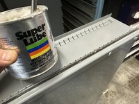
I gave all of the drawer slides a liberal coating of Super Lube.
 
To avoid these ads, REGISTER NOW!
OP
G

Grant Gunderson

Well-known member
Joined
May 17, 2013
Messages
2,325
Location
Bellingham, WA
IMG_6846.jpeg
Same with the drawer edges. Should keep everything feeling smooth.
IMG_6849.jpeg
I then dropped in a foam insert from one of the Craftsman drawers. I think I might be able just about combine two craftsmen drawers into one of the Listas….
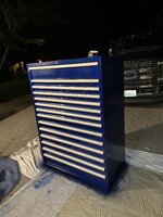
This is when I realized the blue on this Lista doesn’t match the blue on my other ones…. After done thought I decided that was going to drive me nuts.
IMG_6853.jpeg
I dragged the cabinet out to the driveway and used a screwdriver to remove the plastic end caps from the handles.
IMG_6854.jpeg
I then tried to remove the aluminum handle trim but quickly decided tgat was a major pain in the ***. So I just taped it all. I then gave the cabinet a quick sand with 1k grit paper.
IMG_6858.jpeg
Two coats of black sealer followed by 3 color coats and the two coats of a 3k polyurethane. After a few hours dry time. I pulled the rake tonight and reinstalled the plastic edge pieces. Will hopefully get it moved back into the garage tomorrow.

IMG_6859.jpeg
It’s the same color to match the large and the Wilton Vise. At somepoint I’ll paint both of my 16 drawer Listas but that’s a big project to undertake since they are full!
 

Cruzan80

Well-known member
Joined
Jul 22, 2015
Messages
4,273
Location
Denver, CO
Thatwas my first thought, but when you said "I landed", made me second guess myself, especially with the hat down covering the face, for anonymity.

Should have known there are never any good pictures of the photographers themselves... 😁
 
OP
G

Grant Gunderson

Well-known member
Joined
May 17, 2013
Messages
2,325
Location
Bellingham, WA
IMG_6861.jpeg
it really cooled off last night. Woke up to a bunch of condensation on the Lista. Not ideal for new paint.
IMG_6862.jpeg
Got it moved into place. When empty it’s not horrible to slide it on the concrete
IMG_6863.jpeg
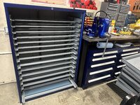
Then install the drawer suspension. Those alone are heavier duty then any Snapon drawer.
IMG_6865.jpeg
I then installed the drawers. Starting to look better
IMG_6864.jpeg
Since I’m not going to ever lock it, I removed the bar between the lock and the back of cabinet mechanism

IMG_6866.jpeg
I need to get the wood cabinet Re hung. But need to modify it first.
IMG_6869.jpeg
I use French cleats when hanging cabinets so need to relocate it on the cabinet I am moving up.
IMG_6871.jpeg
I used my impact driver to zip out the pocket screws holding the French cleat to the cabinet
IMG_6896.jpeg
I then placed it in the wall to measure the correct height.
IMG_6898.jpeg
Then used a red marker to mark its new height on the cabinet.
 
OP
G

Grant Gunderson

Well-known member
Joined
May 17, 2013
Messages
2,325
Location
Bellingham, WA
IMG_6901.jpeg
I relocated the French cleat and the backer board. Then used my Festool Vecturo to notch the side of the cabinet
IMG_6902.jpeg
Not perfect, but you will never see it.
IMG_6910.jpeg
Got the cabinet hung back up and used some structural screws to lock it in place. Then cleaned up the front of the shop and reorganized the wood cabinets.
IMG_6911.jpeg
My original plan was to sell the craftsman stack as it’s where I planned on the Monarch 10ee residing. I decided to move the craftsman stack there at least until I get the Lista dialed in. Besides with my on going divorce I very well may sell the house after and build a custom place…
IMG_6912.jpeg
Testing the drawer layout. Trying to decide what’s the most efficient way to set up the Lista for my workflow and ideally combine some drawers.
 

HogDude

Well-known member
Joined
Dec 25, 2020
Messages
229
Location
Nebraska
IMG_6901.jpeg
I relocated the French cleat and the backer board. Then used my Festool Vecturo to notch the side of the cabinet
IMG_6902.jpeg
Not perfect, but you will never see it.
IMG_6910.jpeg
Got the cabinet hung back up and used some structural screws to lock it in place. Then cleaned up the front of the shop and reorganized the wood cabinets.
IMG_6911.jpeg
My original plan was to sell the craftsman stack as it’s where I planned on the Monarch 10ee residing. I decided to move the craftsman stack there at least until I get the Lista dialed in. Besides with my on going divorce I very well may sell the house after and build a custom place…
IMG_6912.jpeg
Testing the drawer layout. Trying to decide what’s the most efficient way to set up the Lista for my workflow and ideally combine some drawers.
Congrats on the mag cover. As usual, you Lista turned out fantastic. As an infrequent follower I'm sorry to hear about your ongoing divorce.
 
OP
G

Grant Gunderson

Well-known member
Joined
May 17, 2013
Messages
2,325
Location
Bellingham, WA
Congrats on the mag cover. As usual, you Lista turned out fantastic. As an infrequent follower I'm sorry to hear about your ongoing divorce.
Thanks. I’m so ready to be done with the divorce stuff. It’s very frustrating at least in this state that the child custody doesn’t default to 50/60 like the Finace portion of it does.
 

MadeByMiller

Well-known member
Joined
Dec 29, 2018
Messages
1,230
Location
Rapid City, SD
As said above, congratulations on the cover and well done on the Lista! Definite cabinet envy here. I can tell you though since you mentioned it, the pallet feet are not easily removable from the Vidmar cabinets. I've done it, but they're spot welded on the bottom as well as stitch welded on the sides.
 
OP
G

Grant Gunderson

Well-known member
Joined
May 17, 2013
Messages
2,325
Location
Bellingham, WA
As said above, congratulations on the cover and well done on the Lista! Definite cabinet envy here. I can tell you though since you mentioned it, the pallet feet are not easily removable from the Vidmar cabinets. I've done it, but they're spot welded on the bottom as well as stitch welded on the sides.
Yeah I noticed that when I looked at them last night. Thinking once I get the lathe parts off of the cabinet saw I’ll just cut a toe kick board for them. Lots of projects on the to do list and so little time it seems.
 
OP
G

Grant Gunderson

Well-known member
Joined
May 17, 2013
Messages
2,325
Location
Bellingham, WA
IMG_6977.jpeg
My lady friend and I took the kids biking at Sun Peaks for the weekend. It’s a great family friendly bike park.
IMG_7165.jpeg
They had a blast!
IMG_7270.jpeg
My other AXS reverb finally needed a rebuild. First time I’ve really had a reassign to use my new interchangeable dove tail jaws that I made. The post requires the urethane shaft clamps, the copper soft jaws and the Rock Shocks factory shaft clamps to service it. If I ever find a nice used boring head I’ll make a dedicated shaft clamp for the post so I don’t need to use the urethane jaws but that’s low on the priority list

IMG_7272.jpeg
The post head was damn tight from the factory. I had to clamp it using the copper jaws
IMG_7273.jpeg
Then use a strap wrench to get it loose
IMG_7275.jpeg
Here you can see the dove tail I added to the Rock Shocks factory shaft clamps. Also see the counter bore for the ball detent. This aligns the shaft clamps in the vise
IMG_7276.jpeg
Works like a dream. Especially when on a typical suspension or post rebuild you are often needing to switch between the multiple jaw types several times over the course of the rebuild.
IMG_7279.jpeg
Here you can see how the copper jaws grip the top of the post so I can torque the top nut.

Other than having to retrieve a stuck down internal floating piston from the post it was a straightforward rebuild. The AXS posts are a dream to service compared to the original Reverbs!
 
OP
G

Grant Gunderson

Well-known member
Joined
May 17, 2013
Messages
2,325
Location
Bellingham, WA
IMG_7365.jpeg
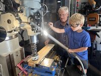
My dad came up to visit for the weekend. I must say it’s a bit tough to see his health and strength decline so fast once he turned 80. However it was really cool to get to play in the shop with him and my 6 year old son Stian. Decided we would build a wooden truck together. Here he is helping Stian with some clearance holes to screw the truck body together
IMG_7375.jpeg
Stian repositioning the mill to drill the second hole
IMG_7401.jpeg
Grandpa lining up the board to cut the wheels with a hole saw
IMG_7411.jpeg
Stian was pretty excited about the wheels!
IMG_7434.jpeg
It’s fun having my dad in the shop. He spent his career designing reactors for nuclear submarines and then was the head of engineering at Hanford’s B-Plant where he designed most of the processing equipment, so he’s always full of good ideas and suggestions for how to do things.
IMG_7444.jpeg
With the on going custody battle with my divorce, it was really nice to just have some quality family time.
IMG_7461.jpeg
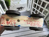
Stian adding his special touch to the trucks art work.
IMG_7465.jpeg
Being in 1 st grade Stians still working on his penmanship, but truth be told mines not much better. Pretty fun way to spend an hour working with Grandpa.
 
OP
G

Grant Gunderson

Well-known member
Joined
May 17, 2013
Messages
2,325
Location
Bellingham, WA
Rode with my lady friend today. My fork started to top out really bad. Something is defiantly off. First things first I'll pull the lowers and then cycle the damper and see if there is an obvious issue.
IMG_7536.jpeg
Right away, I ran into a problem with the spring side nut not wanting to release it just spun the shaft in the fork. Humm.... How am I going to get it out?
IMG_7546.jpeg
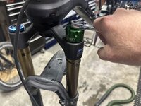
I removed the top cap using one of my Abby fork sockets. I had the Park ones before, and these are light years better.
IMG_7547.jpeg
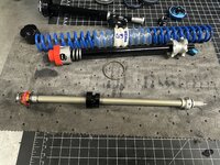
On this fork, I am running the Push AC3 spring conversion. It uses an Air bottom out to ramp it up at the end. Exact opposite of the Vorspring Smashpot that I am running on the other bike and that I prefer over the Push for numerous reasons.
IMG_7551.jpeg
The spring preload and the spring then pull straight out.
IMG_7552.jpeg
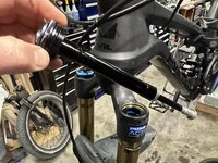
I then used my Fox service tool to remove the damper from the lower. No luck on being able to pull the lowers down enough to get access to the bottom half of the spring shaft. So time to pull the fork from the bike.
IMG_7558.jpeg
I pull the stem so I can drop the fork. I've been really happy with the Ti bolts that I have been running. After a few years they have held up great.
IMG_7561.jpeg
I had to pull the fork, as the handle bars blocked access to pull the damper up and out. With the Damper out, I hand cycled it. Lots of Cavitation noise and it tops out pretty hard. It needs a full rebuild. I'll come back to that in a bit.
IMG_7563.jpeg
I haven't pulled the fork from this bike since I built it a few years ago. I had recently switched over to exclusively using Ted-Gel for my carbon assemblies. So it was nice to see that It has held up very well, especially in the wet PNW.
IMG_7566.jpeg
Bearings are still in surprisingly good shape. The lower is just starting to have one rough spot.
IMG_7565.jpeg
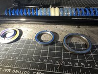
Looking at the compression ring it has very even wear on it. Good sign of a nice tight head set. I'm sure I could get more life out of it, but since I got the fork out, I'm going to replace it.
 
OP
G

Grant Gunderson

Well-known member
Joined
May 17, 2013
Messages
2,325
Location
Bellingham, WA
IMG_7570.PNG
I'm using an app called Pro Bike Garage that links to my Strava for tracking maintenance on all of my bikes and componets. This fork now has 4701KM on it! May not sound like a lot to Moto heads, but thats a ton on a bike fork. Especially given the type of tech trails I like to ride. So its not surprising I need to do some heavy service.

IMG_7574.jpeg
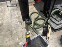
I clamped some UHMW into my vise, stuffed a paper towel into the fork, and then pressed down, while I attempted to unscrew the nut from the lower spring shaft. Notice the vise jaws on the bench. I'm in the process of figuring out new foam / layouts for the tool boxes.
IMG_7575.jpeg
The damn compression washer is not wanting to come off!
IMG_7576.jpeg
Ended up tapping the shaft out of it wiht a brass pin punch.
IMG_7577.jpeg
I finally have the lowers off!
IMG_7581.jpeg
A pick gets the lock ring off of the bottom of the uppers holding the lower spring shaft in.
IMG_7582.jpeg
I really prefer the retaining rings that Sram uses over the Fox style.
 

Attachments

  • IMG_7578.jpeg
    IMG_7578.jpeg
    501.1 KB · Views: 8
OP
G

Grant Gunderson

Well-known member
Joined
May 17, 2013
Messages
2,325
Location
Bellingham, WA
IMG_7584.jpeg
The lower spring shaft is now out. The lower bushing seems to have a lot of play in it.
IMG_7604.jpeg
I heated the end with a torch to free up the lock tight.
IMG_7606.jpeg
and then unscrewed the foot from it.
IMG_7607.jpeg
That was an excessive amount of lock tight on it!
IMG_7610.jpeg
Got the bushing off. I'll see if I can find a new inner bushing to press into it. Notice the nylon ring that acts as a bumper. It's missing one on the top out side, so I'll add one to it. So good news, no major damage to the spring assembly.
IMG_7578.jpeg
A Pedro's DH tire lever is the best thing I have found for removing the dust wipers.
With the wipers out, I inspected the bushings for wear, and they looked great. I then installed the lowers onto the uppers with nothing else, to check for the bushing fit. Nice and tight and good glide, so the fork bushings are still in great shape!
 
OP
G

Grant Gunderson

Well-known member
Joined
May 17, 2013
Messages
2,325
Location
Bellingham, WA
IMG_7593.jpeg
Time to crack open the Grip2 damper. First I need to pull the rebound shaft. I modified the Fox factory clamps to use my dovetail system. Sure is nice on a project like this where I need to switch back and forth a bunch.
IMG_7594.jpeg
Thats a lot of very foamy oil. Clearly there is a seal issue. Granted the Grip2 is a semi sealed damper (self bleeding) unlike the totally sealed damper of the Grip1 or Fit dampers. Seems like we are slowly going back to the days of open bath forks... just with better seals.
IMG_7596.jpeg
Here is the rebound shaft pulled from the damper. The external adjustments for High/ Slow speed are on the Right. The assembly on the left is the valving.
IMG_7597.jpeg
I then removed the compression side from the Damper tube.
IMG_7612.jpeg
Thats the main guts out of my Fox 36.
IMG_7613.jpeg
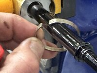
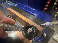
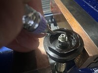
One of the hardest parts of servicing these, is getting the tiny retaining ring out of the top of the compression assembly. Best way I know of is to use a dental pic inserted into the hole in the side, to push the ring in, then use a second to lift it out.
IMG_7614.jpeg
It's tiny!
IMG_7615.jpeg
The inner adjusted gets turned fully CCW and lifted out.
IMG_7616.jpeg
Followed by the needle valve.
IMG_7633.jpeg
A 3mm hex, then removes the compression valving shim stack from the other end. You can tune the damper by changing the size / order of these shims.
 
OP
G

Grant Gunderson

Well-known member
Joined
May 17, 2013
Messages
2,325
Location
Bellingham, WA
IMG_7634.jpeg
Its best to keep the shim stack in order, but if you do screw it up, Fox has the stack published on their site for the stock tune.
IMG_7638.jpeg
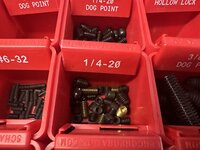
Two dog point set screws hold the valve head on.
IMG_7639.jpeg
I can then pull the rest of the compression system apart. Pretty simple.IMG_7640.jpeg
I noticed this bright spot on the shaft last time I rebuilt it. Its clearly pretty worn, so I think I'll replace the compression head with the new VCC version.
 
OP
G

Grant Gunderson

Well-known member
Joined
May 17, 2013
Messages
2,325
Location
Bellingham, WA
IMG_7618.jpeg
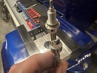
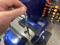
Next, I need to pull the rebound shaft apart. The foot is held on by a single set screw, then it unscrews.
IMG_7620.jpeg
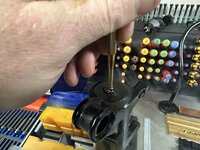
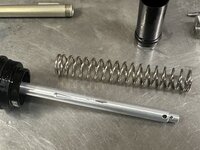
Having a magnet under it to catch the spring loaded ball detent is a must. This is also why I try to keep a selection of loose ball bearings and springs on hand for the occasion when they fly across the shop.
IMG_7623.jpeg
There is two shims under the foot.
IMG_7625.jpeg
The adjuster shaft then pulls out.
IMG_7626.jpeg
The black seal head can then slide off. It has a one way o-ring in it. So its important it gets reinstalled in the correct orientation once the o-ring is replaced.
IMG_7629.jpeg
The rebound valve stack then unscrews. Unless you have a very fine Torque wrench and precision shim stock on hand, dont mess with this. It has to be very precisely recalibrated when re-asembled.
IMG_7630.jpeg
Then the rebound adjuster needle comes out.
IMG_7632.jpeg
And there is the major parts of the rebound portion. I need to pick up a seal kit tomorrow before I break it the rest of the way down.
 
To avoid these ads, REGISTER NOW!
Top Bottom