Is this BP a 4hp?, what vfd did you order?

You are using an out of date browser. It may not display this or other websites correctly.
You should upgrade or use an alternative browser.
You should upgrade or use an alternative browser.
Bought a used Bridgeport mill, what do I have
- Thread starter A747
- Start date
I do appreciate the support comments so far. The VFD arrived a couple of days ago and the next couple of weeks or so will be to figure out what is needed electrically to get the mill running to see if all of the mill controls work and the condition of the motor and bearings. Will report back for more questions.
laser3kw
Well-known member
the operator has to "hold" each axis while using the other axis. If you let go of the "Y" axis and take a heavy-ish cut on the "X", the "Y" can back drive and move off position (my experience)Usually they don't hold the table still without a drive motor to hold the screw still,
Be aware, the vfd should only be used to power the motor. It does not put out a "sine" wave that is needed for the controller or any other 60hz power line dependent equipment. A rotary phase converter would be the choice for thatThe mill will be the only three phase motor that I currently have so the VFD looks to be the best and quickest option to get started.
Another caveat: if using the vfd on the motor, the vfd output must go directly to the motor with no interruption. DO NOT hook the vfd to the forward / reverse drum switch and switch the motor direction while the vfd is active outputting power - it will ruin the vfd!
You must use the vfd control panel or hook up the appropriate switches (forward /reverse etc) on the vfd terminal strip. You may also need to adjust parameters on the vfd to get the needed acceleration / deceleration for the motor.
Last edited:
dutchgray
Well-known member
Both my Bridgports (I have a step pulley and a variable speed) the only 3 phase needs are the main motor and the coolant pump, the rest of the machine and all the controls run of the transformers various outputs, which is single phase input and configurable to different voltages. They are quite easy to convert to single phase power.the operator has to "hold" each axis while using the other axis. If you let go of the "Y" axis and take a heavy-ish cut on the "X", the "Y" can back drive and move off position (my experience)
Be aware, the vfd should only be used to power the motor. It does not put out a "sine" wave that is needed for the controller or any other 60hz power line dependent equipment. A rotary phase converter would be the choice for that
Another caveat: if using the vfd on the motor, the vfd output must go directly to the motor with no interruption. DO NOT hook the vfd to the forward / reverse drum switch and switch the motor direction while the vfd is active outputting power - it will ruin the vfd!
You must use the vfd control panel or hook up the appropriate switches (forward /reverse etc) on the vfd terminal strip. You may also need to adjust parameters on the vfd to get the needed acceleration / deceleration for the motor.
laser3kw
Well-known member
the vfd outputs "chopped" square wave, not a clean sine wave. Motors will work, but things like computers and such, not so much. Is it worth a roll of the dice and see if the controller pukes? IDK
My intent is to make the power supply swap as simple as possible. The power cord from the Bridgeport motor will be wired to the output of the VFD. All control functions will be done using the control switches on the Bridgeport. I will probably play with the motor acceleration times and the braking resister to not having to use the spindle brake on the machine. Other than that, I see no other changes required.
OP FYI, lots of info on hooking 3p mills up 1p power here:
Transformers, Phase Converters and VFD
Machine voltage issues, three phase via single phase power, and variable frequency drives discussion >> moderator JST
www.practicalmachinist.com
Firebrick43
Well-known member
It should be 2hp for a series 1 with a 2j head. Earlier machines had options for smaller motors than 2 hp.Is this BP a 4hp?, what vfd did you order?
Only the series 2's got the 4hp motors
My intent is to make the power supply swap as simple as possible. The power cord from the Bridgeport motor will be wired to the output of the VFD. All control functions will be done using the control switches on the Bridgeport. I will probably play with the motor acceleration times and the braking resister to not having to use the spindle brake on the machine. Other than that, I see no other changes required.
Be aware of where you place the vfd. They can create EMI with older logic circuits in CNC controllers or wires that are parallel to the power cable. They make VFD rated cable that I would highly suggest, it not only has the proper insulation for the voltage spikes but also is shielded helping tremendously to reduce EMI. If you place the VFD in the cabinet its wise to place aluminum shields between it and other circuits. Make sure the shielding on the wire is brought back and terminated according to the instructions.
Also your motor isn't VFD rated. This is still fine to use with a VFD but its recommended that you don't go below 20 hertz in speed to protect the insulation on the wires inside the motor.
Last edited:
laser3kw
Well-known member
again, a vfd should not be used as a global power supply / power converter. They are meant to control a three phase motor and that's it.The power cord from the Bridgeport motor will be wired to the output of the VFD.
You can certainly try it and see if the mill will power up and function. If you have problems / error messages / quirky operation, look at the vfd as the common thread to the problems. I know the servo drives are going to be grumpy and, if the HMI is that old, it too will be glitchy.
I hope the vfd is a 5 or 7 horsepower to take care of the extra current requirements. The MCCB rating will be a good indication to the current requirements.
Keep us posted. I'd be interested to see if it works in any form and what troubleshooting it will take.
Grant Gunderson
Well-known member
As others have stated DO NOT connect it that way!. The power cord from the Bridgeport motor will be wired to the output of the VFD. All control functions will be done using the control switches on the Bridgeport. I will probably play with the motor acceleration times and the braking resister to not having to use the spindle brake on the machine. Other than that, I see no other changes required.
 You must connect motor leads directly to the VFD.
You can then. Run wires from the factory drum switch to the VFD or just use new forward / reverse controls for the VFD.

No real need to use a breaking resistor on a Bridgeport VFD (other than wiring an electrical emergency stop). The factory breaking system works well, lasts forever and is important for changing collets (unless you put it in back gear to do that).
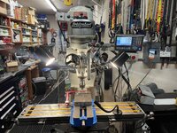
Last edited:
So pretty. Lotta love put into that machine.As others have stated DO NOT connect it that way!
You can then. Run wires from the factory drum switch to the VFD or just use new forward / reverse controls for the VFD.
No real need to use a breaking resistor on a Bridgeport VFD (other than wiring an eclectic emergency stop). The factory breaking system works well, lasts forever and is important for changing collets (unless you put it in back gear to do that).
Grant Gunderson
Well-known member
Thanks! I fully tore it down to the last screw when I got it a few years ago.So pretty. Lotta love put into that machine.
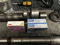
I just this week replaced all of the spindle / gear box bearings and converted it to a sealed grease system from the oil-loss system

Spindle runout now exceeds my capabilities to measure it.
Last edited:
Grant Gunderson
Well-known member
Thanks. Had a few massive life changes in the last 6 months. Finally in a position to get back to the lathe project soon as I finish my Wilton 3C rebuild in my Garage Thread.LOL, I recognized Grants garage before I saw that it was him, his lathe post was/is addictive…
Back to the OP’s thread. I hope we can get him to post some pics of his progress as he goes. Will be interesting to see how it pans out for him.
Last edited:
laser3kw
Well-known member
Here is the Push Button Box for my vfd conversion. It has
lights
chip air nozzle
air draw bar in/out
jog forward / reverse
forward / reverse
rpm adjust
E-stop and real time tach.
back side shows the pneumatic solenoids
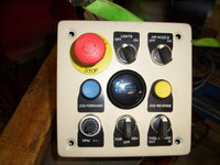

lights
chip air nozzle
air draw bar in/out
jog forward / reverse
forward / reverse
rpm adjust
E-stop and real time tach.
back side shows the pneumatic solenoids
laser3kw
Well-known member
PS ^^^^
I highly recommend "Carolina Laser" (legend-plates.com) for standard and custom legend plates. They have an online app that lets you build your legend plate using many different sizes, shapes and colors. They cut mine and shipped the day after I ordered them.
I highly recommend "Carolina Laser" (legend-plates.com) for standard and custom legend plates. They have an online app that lets you build your legend plate using many different sizes, shapes and colors. They cut mine and shipped the day after I ordered them.
There's a flood of information coming, I'm just trying to process it all. For starters my Bridgeport is a Series 1 with a 2HP motor wired for three phase 208VAC. From the manufacturers plate on the motor, for low voltage (200V) motor is rated for 6.5 amps at 60 hz. I'm going to use a DuraPulse GS11N-23PO, rated for 3 HP at 11Amps.
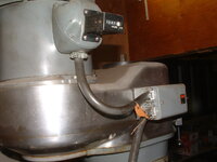
Power to the mill motor goes through the Forward/Reverse/Off rotary switch then to the motor (see pictures). If I'm understanding the comments correctly, I need to bypass the rotary switch controlling the motor and wire the motor directly to the VFD? This will obviously require a remote function switch to the VFD
Power to the mill motor goes through the Forward/Reverse/Off rotary switch then to the motor (see pictures). If I'm understanding the comments correctly, I need to bypass the rotary switch controlling the motor and wire the motor directly to the VFD? This will obviously require a remote function switch to the VFD
Attachments


laser3kw
Well-known member
So far, so good - just open the pecker head on the motor and connect the three motor wires to the three vfd output terminals (U,V,W / T1,T2,T3). Disconnect the wires going to the drum switch. 12 gauge will handle up to 20amp.
that will allow you to run the motor from the VFD panel - forward and reverse.
you can add separate push button box it you like - it is real handy. Plenty of help here to step you through it.
You will have to hand crank the axis.
that will allow you to run the motor from the VFD panel - forward and reverse.
you can add separate push button box it you like - it is real handy. Plenty of help here to step you through it.
You will have to hand crank the axis.
Last edited:
Grant Gunderson
Well-known member
That’sThere's a flood of information coming, I'm just trying to process it all. For starters my Bridgeport is a Series 1 with a 2HP motor wired for three phase 208VAC. From the manufacturers plate on the motor, for low voltage (200V) motor is rated for 6.5 amps at 60 hz. I'm going to use a DuraPulse GS11N-23PO, rated for 3 HP at 11Amps.
Power to the mill motor goes through the Forward/Reverse/Off rotary switch then to the motor (see pictures). If I'm understanding the comments correctly, I need to bypass the rotary switch controlling the motor and wire the motor directly to the VFD? This will obviously require a remote function switch to the VFD
 correct.
 I did place a plug between the Bridgeport motor and VFD in. See I ever needed to move it (never have) so I’d just hardwire it to the VFD.
It’s worth noting once you get to hooking up a forward / reverse switch, all you have to do is change 1 wire position on a 3 phase motor to change its direction. That’s helpful to know in case you are getting a reverse spindle direction of what you anticipated
A747, you should check to see if your VFD can use the original switch as an input to it's fwd/rev control. So the AC power would go from the wall to the VFD then to the motor. The switch (if the VFD can do this) would go to the VFD as the direction input control.
laser3kw
Well-known member
Grant Gunderson did just that ^^^^^The switch (if the VFD can do this) would go to the VFD as the direction input control.
I was going to do that and then took a left turn and went down a rabbit hole
 .
.So it can be done. My original plan was to use the mill controls as much as possible.
Another question is speed control. My mill has a variable speed handwheel. I don't remember how speed is adjusted on induction motors but can the mill handwheel still control spindle speed with a VFD?
Another question is speed control. My mill has a variable speed handwheel. I don't remember how speed is adjusted on induction motors but can the mill handwheel still control spindle speed with a VFD?
dutchgray
Well-known member
You absolutely could wire it this way if you wanted to, as long as the drum switch gets wired out of the cable and instead gets wired to the VFD for direction control and you go into the control cabinet, find the motor contactor, pull the power feeds out of it, (from memory just phase 2 and 3 and they are short links from the coolant pump condactor) so it still operates but has no power, then use any of its available contact sets as the control switch for motor run on the VFD.My intent is to make the power supply swap as simple as possible. The power cord from the Bridgeport motor will be wired to the output of the VFD. All control functions will be done using the control switches on the Bridgeport. I will probably play with the motor acceleration times and the braking resister to not having to use the spindle brake on the machine. Other than that, I see no other changes required.
This way leaves the factory wiring as un modified as possible and is easily reversible.
laser3kw
Well-known member
Yes, it is a variable speed head, you can crank the hand wheel on the upper right side of the head and it will alter the belt sheave to vary the spindle speed. Only adjust while the motor is running.can the mill handwheel still control spindle speed with a VFD?
Grant Gunderson
Well-known member
Yes. However I and others have found using a new set of controls for spindle directions etc mounted bellow a DRO on the right side of the machine is a much more convenient and ergonomic location than the factory drum switch location on the top left of the head. Controls are pretty cheap so you can always try it one way and change it latter.So it can be done. My original plan was to use the mill controls as much as possible.
Another question is speed control. My mill has a variable speed handwheel. I don't remember how speed is adjusted on induction motors but can the mill handwheel still control spindle speed with a VFD?
You can adjust spindle speed two ways. With the handle on the head (preferred method) or with a pot on the VFD (not ideal) as the pot (potentiometer) and VFD basically change the hertz the motor sees so you have a limited power band.
Best thing to do in your case and the simplest is not to use the VFD as a speed control at all. Simply set it to output 60hz so the motor runs at full name plate speed / power and then just use the hand-wheel on the head to adjust speed as Bridgeport originally designed.
I’m using a Pot on my VFD to change spindle speed as I have a J-head so it does save me from changing the belt position as often (still need to for big speed changes).
Don’t get too caught up in the VFD tech. Keep it simple and just use it as a power converter. You will need to run control wires ( ideally in separate conduit from the power connectors) back to the factory drum switch. These will be low voltage usually either 12 or 24v depending on the vfd.
After you get it powered I’d then advise tearing the head down and inspecting the gear box and spindle bearings. They are not too expensive or difficult to change and unless they have been changed it will make a big difference in the performance.
Last edited:
laser3kw
Well-known member
^^^ very wise. Start simple. Bells and whistles laterDon’t get too caught up in the VFD tech. Keep it simple and just use it as a power converter.
I use the hi/lo back gear and hand crank on the variable speed to get the range I want and use my speed pot to "trim" the speed until I hear the sound I want coming off the cutter.
OP: do you know about the Hi / lo back gear? There is a little lever on the right side behind and lower than the variable speed crank. With the motor off, you flip it front or back and rotate the spindle by hand until you hear or feel the back gear drop in. That sets the spindle in "lo" gear or "hi" gear on the spindle drive. Dual range so to speak.
This sounds like a great project.
rsanter
Well-known member
Making sure to lock the table in the axis you are not moving is a first step. Just keep in mind that the table locks are not great. They are good but not great.Someone already answered for me but yes, I don't have three phase power in my garage thus the need for the VFD. The mill will be the only three phase motor that I currently have so the VFD looks to be the best and quickest option to get started.
Looking under the table this morning, it appears that I have a ball screw setup. It looks exactly like the ball screw from the drawing sent by RoninB4. If I'm understanding the comments correctly, the ball screw should not be an issue with manual operation as long as I lock the table in the axis I don't want moving during milling operations. Since I don't have the dial indication on the X&Y axis I will need some sort of DRO. The mill already has the linear scales (correct term?) installed for the Anilam controller. Can those be used for another brand of DRO?
The other option is to try to get the Anilam controller functional as a DRO only, probably a long shot.
Like some, perhaps most of you on GJ, I'm a hobbyist and enthusiast for metal working. I don't plan putting the Bridgeport through a work out. My ultimate goal is to be good enough to make car parts for my vintage British sports car when I need to. I was planning on using the Jet vertical mill at my local Makers Space when I ran across the Bridgeport. The convenience factor can't be overstated.
Keep in mind that if you are taking to big of a bite with the cutter, you may get some creep in the table. This may just be a learning. Excersize for you till you get the hang of how big a bite you can take.
On the CNC machine, the machine(computer/controller) will “lock” the table using the motor by exciting the poles of the motor to not turn. I’m actually kind of wondering if you could leave the motors in place and use them as power feeds and as table locks.
I know one place I worked had a CNC lathe that allowed the operator to move the carrrage and cross feed using dials on the control,panel
Firebrick43
Well-known member
Nearly all CNC controls can be "power feed" with the controller. This particular control you would hit the hand button, Select X, Y or Z axis, an then push the + or - button next to the hand button to jog it. To adjust the speed of the feed you can either push the Feed button and enter an amount or use the feed percentage buttons to raise or lower.Making sure to lock the table in the axis you are not moving is a first step. Just keep in mind that the table locks are not great. They are good but not great.
Keep in mind that if you are taking to big of a bite with the cutter, you may get some creep in the table. This may just be a learning. Excersize for you till you get the hang of how big a bite you can take.
On the CNC machine, the machine(computer/controller) will “lock” the table using the motor by exciting the poles of the motor to not turn. I’m actually kind of wondering if you could leave the motors in place and use them as power feeds and as table locks.
I know one place I worked had a CNC lathe that allowed the operator to move the carrrage and cross feed using dials on the control,panel
Note that when you switch the back gear in/out it changes the direction of the spindle. When we installed VFD drives and controls on half a dozen series II machines we placed a little magnet on the handle and a magnetic switch where the handle was when it was in low. We had that going to the VFD and the parameters set to reverse the spindle direction automatically so people didn't have to think about it and invariably run the cutter backwards.
One day we let a contractor use one to drill some holes prior to being converted and he burned up two drill bits before someone came over to investigate the smell and realized he was in reverse practically hanging off of the quill lever.
We removed the crappy and noisy reeves drives and placed a rheostat to control the speed of the motor as an input to the VFD. We replaced the reeves drive with poly vee (serpentine style belts) belts and sheaves
We also placed a momentary push button and a selector switch. The selector switch had tap mode and regular mode. When in tap mode it reversed the direction of the spindle unless the momentary button was pushed. So you would put it in low gear, slow it down to 20 rpm or so, and with one hand pushing on the momentary button feed the tap into the hole with the quill and after it engaged remove your hand from the quill and let it self feed. Once it went thru the hole or was deep enough by the DRO you released the momentary button and the spindle automatically reversed. You applied just a little up pressure on the quill as it exited the hole to keep the tap from dwelling there and ruining the first thread.
A lot of series II had this feature from the factory but it did it with contactors. Once converted to VFD you could throw all that stuff away.
As others have said, I wouldn't try to do all this at first, but its very cheap to implement and very handy if you already have a VFD.
Last edited:
An update on my progress. I had a couple of false starts with the wiring but the Bridgeport is finally wired up enough to check for noise and rotation. No external STOP/START yet, currently all done on the VFD PBs. With some trepidation, hit START and with great relief it powered up and ran CCW which I believe is reverse. I wasn't too concerned at the time, simply swap two motor power leads at the VFD. I later realized that the mill was in Low gear so all is normal. I again appreciate all the assistance here. The next step is to start buying the equipment to using the mill. I will also need to start looking to see if the CNC controller still works. With the ten million circuit board in the control box, I wouldn't know where to start, time to call in an expert.
Attachments

dutchgray
Well-known member
I would have kicked the contractor out the workshop and told the guy to never come back, any one too thick to kill a drill running backwards without realising, let alone a second bit doesn't deserve to use others machinery.One day we let a contractor use one to drill some holes prior to being converted and he burned up two drill bits before someone came over to investigate the smell and realized he was in reverse practically hanging off of the quill lever.
Firebrick43
Well-known member
While I don't disagree with you, Those kind of actions become political quagmires in large bureaucrat ran companies. He was asked never to touch any of our machinery again, and any machining that was required we would gladly assist him in to the fullest of our capabilities.I would have kicked the contractor out the workshop and told the guy to never come back, any one too thick to kill a drill running backwards without realising, let alone a second bit doesn't deserve to use others machinery.
dutchgray
Well-known member
A large bureaucratic company here would be very unlikely to let an outsider use machinery in the first place, the health and safety implications, not being trained on the machinery, not being covered by insurance to even be in the workshop, it wouldn't be worth the risk.While I don't disagree with you, Those kind of actions become political quagmires in large bureaucrat ran companies. He was asked never to touch any of our machinery again, and any machining that was required we would gladly assist him in to the fullest of our capabilities.
Firebrick43
Well-known member
The powers that be did at this company?A large bureaucratic company here would be very unlikely to let an outsider use machinery in the first place, the health and safety implications, not being trained on the machinery, not being covered by insurance to even be in the workshop, it wouldn't be worth the risk.
We had several contractors that were very talented and did a lot of work for us, especially the millwright company and the machine scraper/rebuilder that assisted in large machine rebuilds every summer shutdown. They some times did smaller machines during the christmas shut down.
The Millwright company kept their large specialized machinery moving forklift that could lift 60k when extended and allowed a few mechs that they checked out to operate it when they were not there and we allowed them to use our 100 ton press, the Bridgeport's, one of the Monarch lathes and drill presses. They were forbidden from touching the Moore jig grinders, the SIP, and any of the large surface grinders however.
Edit,
Hell, I was one of the few mechanics that was allowed to touch the SIP, 50 percent of the toolmakers were not allowed to touch it let alone the 1200 other people in the plant. Because I treated it like the piece of art it was and fixed some boo boos by two tool makers with a lapse of judgement they would actually let me run it. I would give my left nut for a nice monarch 10EE and right one for a SIP Hydroptic
Last edited:
dutchgray
Well-known member
Only after tooling was ruined, here in the UK in most corporate type places wouldn't have allowed a "contractor" to touch anything other than what they were there to do, would probably be escorted whilst on the property, they wouldn't be allowed to use machinery to begin with.The powers that be did at this company?
Not so bad in smaller places.
gastgarage
Well-known member
Your mill looks like it has the same electrical box as mine, labeled "high" and "low" speed, this is actually a switch to reverse the motor wiring when the mill is physically in low gear and running the quill backwards.An update on my progress. I had a couple of false starts with the wiring but the Bridgeport is finally wired up enough to check for noise and rotation. No external STOP/START yet, currently all done on the VFD PBs. With some trepidation, hit START and with great relief it powered up and ran CCW which I believe is reverse. I wasn't too concerned at the time, simply swap two motor power leads at the VFD. I later realized that the mill was in Low gear so all is normal. I again appreciate all the assistance here. The next step is to start buying the equipment to using the mill. I will also need to start looking to see if the CNC controller still works. With the ten million circuit board in the control box, I wouldn't know where to start, time to call in an expert.
Are you planning to use a contactor (like Clough42 and imitators on YouTube)? I've gone down that road with the same mill (motor is 3p 240v 1.5 HP) and have it all wired up and running on the VFD, but can't get the remote wiring to operate the contactor. I've either got something else wired wrong, have the contactor wired wrong or have the wrong contactor.
Clough42 and most others on Youtube are using the VFD to run 110 motors and the wiring is slightly different.
Last edited:
solo machinist
Well-known member
A747, I was wondering how your mill is coming along.
My boss at work got a mill (old cnc) out of storage. We were wondering if it's worth keeping or scrap.
The ways look new or it's been re scraped. Really good shape for as old as it is.
It has the same Anilam control, I think? We have another one with newer controls (still old) but clunky to use.
I haven't spent much time trying to learn how to program either one. How are you coming along?
My boss at work got a mill (old cnc) out of storage. We were wondering if it's worth keeping or scrap.
The ways look new or it's been re scraped. Really good shape for as old as it is.
It has the same Anilam control, I think? We have another one with newer controls (still old) but clunky to use.
I haven't spent much time trying to learn how to program either one. How are you coming along?
Lots of nice ways to add switches to control the VFD remotely. What's a good source for these? McMaster-Carr?
As others have stated DO NOT connect it that way!
You can then. Run wires from the factory drum switch to the VFD or just use new forward / reverse controls for the VFD.
No real need to use a breaking resistor on a Bridgeport VFD (other than wiring an electrical emergency stop). The factory breaking system works well, lasts forever and is important for changing collets (unless you put it in back gear to do that).