To avoid these ads, REGISTER NOW!

ZMotorsports Shop Projects 2.0

To avoid these ads, REGISTER NOW!

Bob Heine

ALLIANCE MEMBER
Joined
Oct 24, 2009
Messages
10,709
Location
Boca Raton, Florida
Mike, congratulations to you and a special congratulations to Chrystal. She supported you in good times and bad. She gave birth to the amazing child you both raised and while working a full-time job, shared the long hours on the road with all your motorsports projects. A lot of wives in that position move on after 35 months!

EDIT: When I survived my incident with the train we were married 41 months and Liane didn't leave me for a four-limbed clown. I am forever grateful for her support and love. If you are surprised it's been 35 years, you're gonna lose it when it's 62! :love:
 
Last edited:
OP
Z

zmotorsports

ALLIANCE MEMBER
Joined
Oct 20, 2009
Messages
21,477
Location
Northern Utah
Mike, congratulations to you and a special congratulations to Chrystal. She supported you in good times and bad. She gave birth to the amazing child you both raised and while working a full-time job, shared the long hours on the road with all your motorsports projects. A lot of wives in that position move on after 35 months!

EDIT: When I survived my incident with the train we were married 41 months and Liane didn't leave me for a four-limbed clown. I am forever grateful for her support and love. If you are surprised it's been 35 years, you're gonna lose it when it's 62! :love:

Thanks Bob. Yeah, I would not be who I am without my wonderful wife.

Maybe now she'll take some of the blame. :ROFLMAO:
 

Just Fishing

Well-known member
Joined
Dec 21, 2020
Messages
57
Location
Utah
Awesome shop @zmotorsports!

Link...


Every time I see Mikes shop I'm in Awe.
One day I'll probably move out of this toxic neighborhood, and if I do I want a big backyard shop for my various projects.


Just last week I was trying to find some tools that I know I have, but where did I put them? :ROFLMAO:
My tiny little 2 car garage isn't cutting it for me.
 
Last edited:
OP
Z

zmotorsports

ALLIANCE MEMBER
Joined
Oct 20, 2009
Messages
21,477
Location
Northern Utah
Every time I see Mikes shop I'm in Awe.
One day I'll probably move out of this toxic neighborhood, and if I do I want a big backyard shop for my various projects.


Just last week I was trying to find some tools that I know I have, but where did I put them? :ROFLMAO:
My tiny little 2 car garage isn't cutting it for me.


Thanks Chris. Sounds like a similar situation as my last neighborhood. Very toxic and deteriorated by the end of our 26 years of being there.

If I can give one bit of advice, don't wait. If you are at all thinking about moving and building a shop, don't hesitate. I could actually feel it take a toll on my mental well-being and my overall health each day pulling in the neighborhood. Once we moved I actually looked forward to driving in the subdivision again and my whole perspective changed.

Besides, things aren't getting any less expensive and the longer you wait, I think the more it will cost.


Congrats to you and your wife for the anniversary Mike!


That FASS return came out sweet, as usual....

Thank you Anders. It's hard to comprehend how fast the first 35 years of marriage went by. While I don't feel "young" any longer, I certainly don't feel old either. :giggle:
 
OP
Z

zmotorsports

ALLIANCE MEMBER
Joined
Oct 20, 2009
Messages
21,477
Location
Northern Utah
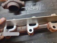
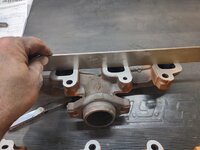
After mowing lawns yesterday afternoon I began flattening the exhaust manifolds using the belt sander. This is my go-to method to true-up or flatten out exhaust manifolds and it has worked extremely well over the years. Most manufacturers that I have read, state that the manifolds should be within .006" of true. I generally shoot for .003" or less with .004" being my max. Unfortunately, over the past 8 or 10 years I have seen some right out the box exceed these specifications.

By removing the top cover off as well as the shelf and I have a good 16-18 inches of flat belt to run the manifolds across.
wj51.jpg

With a little finesse I can get to less than .003".
wj52.jpg

wj53.jpg

While I was truing up the exhaust manifolds, my son was focusing on cleaning the engine bay using SD-20 degreaser and some paper towels. The engine bay cleaned up very nicely, but then again, it was actually pretty clean to start with, especially for a 20 year old Jeep with 200k+ miles on the clock.

After he was done in the engine bay, we wanted to confirm the A/C system was tight after replacing the A/C evaporator, so we connected the compressor, connected the lines and gauges and fired up the vacuum pump and pulled the system into a vacuum. It held for the half our or so we were putting tools away so we decided to leave it overnight. I checked it first thing this morning and it hadn't moved at all so we have confirmed the system is tight.
wj54.jpg


Thanks for looking.
 

ntsqd

Well-known member
Joined
Jan 22, 2005
Messages
997
Location
Lower left coast
During my lower division years I worked in a racing engines shop mostly doing some of the one-off and weird fabrication & machining. Guess what we used for flattening header flanges and exhaust manifolds? A really BIG horizontal belt sander. It was made for doing exactly that type of job, water cooled belt and platen. Scary thing, operated with a foot switch. I swear it dimmed the lights on start-up. I don't think it held any tighter than what you're getting out of your belt sander.
 
OP
Z

zmotorsports

ALLIANCE MEMBER
Joined
Oct 20, 2009
Messages
21,477
Location
Northern Utah
Nice job on the exhaust manifold flatness restoration!

During my lower division years I worked in a racing engines shop mostly doing some of the one-off and weird fabrication & machining. Guess what we used for flattening header flanges and exhaust manifolds? A really BIG horizontal belt sander. It was made for doing exactly that type of job, water cooled belt and platen. Scary thing, operated with a foot switch. I swear it dimmed the lights on start-up. I don't think it held any tighter than what you're getting out of your belt sander.

Thanks guys. This method has worked well for me for many years and much quicker than having to mount it to the mill table. I don't know if it would get any straighter or flatter on the mill. Glad to hear others have done the same thing to flatten out manifolds and/or header flanges.

That being said, these were not that far off as I did the same thing to them 5 years ago when we installed them new out of the box. They weren't leaking and were sealed up well, I just touched them across the belt sander while they were off to confirm and check before reinstalling them.
 
OP
Z

zmotorsports

ALLIANCE MEMBER
Joined
Oct 20, 2009
Messages
21,477
Location
Northern Utah
Congrats on the 35! Few months short of 32 yrs for wife & I

Thanks Randy and congratulation on the 32 year anniversary coming up for you and the Mrs.


Any specs on that belt sander?

It is a Wilton 12" disc/48" belt combination sander. There are several versions available with slightly smaller discs (9") and lesser HP motors if space is a concern or you want to keep costs down, but mine is the 6x48" belt and 12" disc model with the 1.5 HP/ 115-VAC motor.

I believe there are a few that are similar such as the Delta and Jet but mine is an older model that was made in Taiwan, so you may be able to find a used one in decent condition. Although, if others are like me, they probably won't ever part with it. Mine is probably one of the most used tools in the shop as it seems like there is always a rough edge that needs to be smoothed or a corner than needs to be rounded off. I've have this one for well over 25-years and had a smaller HP Delta model prior to that for a few years. I think the particular Delta model I had before was more geared towards woodworking than metal fabrication as I picked it up at a yard sale back in the early 90's before I really knew the differences.

For my usage I have found a 60-grit disc and a 120-grit belt work the best for the work I do. The disc knocks off the material quickly and then I touch it up using the 120-grit belt for a more finished and detailed appearance, but you could run about any grits you wish as the belts and discs are available in a wide range of various grits.
 

aka Larry

Well-known member
Joined
May 2, 2012
Messages
8,099
Location
Eastern, NC
That being said, these were not that far off as I did the same thing to them 5 years ago when we installed them new out of the box. They weren't leaking and were sealed up well, I just touched them across the belt sander while they were off to confirm and check before reinstalling them.

This reminds of my buddy who had an F-150 with the 3.5 EB engine. I was in his office where the truck's cast OE exhaust manifold was sitting on a table behind him. The flange was so warped I could tell it from 5 feet away!

It was so bad I doubt that Mike or anyone else could fix it with a belt sander or a mill.
 
To avoid these ads, REGISTER NOW!
OP
Z

zmotorsports

ALLIANCE MEMBER
Joined
Oct 20, 2009
Messages
21,477
Location
Northern Utah
Hope everyone had a nice weekend.

For starters Saturday morning after a few cups of coffee and sitting on the deck, I finished bead blasting my son's oil pan and got it wiped down with Wax & Grease Remover, then a few coats of paint.
wj55.jpg

wj56.jpg

I then had a small job on my "to do" list for the shop which required a bit of machining and welding. I had an old pair of locking pliers that I made a slide hammer adapter for the threaded bolt years ago. It worked well, but was not in line with the jaws and therefore, at times slipped off when using the slide hammer. I had put this small project on my shop "to do" list a couple of years ago when I built the new shank and handle for my old Snap-on slide hammer weight. I just never made the time to modify the pliers. Saturday I took about an hour and made time. I also had set aside a smaller pair of locking pliers so I would make two threaded bungs and modify two pairs.
pliers1.jpg

Once the bung was threaded on one end, I cut it at an angle to make two separate bungs, then chucked up the other one and threaded it in the lathe. With two bungs threaded, cut and a radius ground into the underside to match the backbone of the pliers, I moved over to the welding table.
pliers2.jpg

One down and one too go.
pliers3.jpg

pliers4.jpg

This should allow the energy to be pulled more directly in line with the jaws.
pliers5.jpg

pliers6.jpg

Both pair TIG welded and cooled.
pliers7.jpg

And test fit on the slide hammer.
pliers7a.jpg


Thanks for looking.
 

PugetDude

ALLIANCE MEMBER
Joined
Mar 13, 2013
Messages
22,481
Location
Superstition Mountains, AZ
Hope everyone had a nice weekend.

For starters Saturday morning after a few cups of coffee and sitting on the deck, I finished bead blasting my son's oil pan and got it wiped down with Wax & Grease Remover, then a few coats of paint.
wj55.jpg

wj56.jpg

I then had a small job on my "to do" list for the shop which required a bit of machining and welding. I had an old pair of locking pliers that I made a slide hammer adapter for the threaded bolt years ago. It worked well, but was not in line with the jaws and therefore, at times slipped off when using the slide hammer. I had put this small project on my shop "to do" list a couple of years ago when I built the new shank and handle for my old Snap-on slide hammer weight. I just never made the time to modify the pliers. Saturday I took about an hour and made time. I also had set aside a smaller pair of locking pliers so I would make two threaded bungs and modify two pairs.
pliers1.jpg

Once the bung was threaded on one end, I cut it at an angle to make two separate bungs, then chucked up the other one and threaded it in the lathe. With two bungs threaded, cut and a radius ground into the underside to match the backbone of the pliers, I moved over to the welding table.
pliers2.jpg

One down and one too go.
pliers3.jpg

pliers4.jpg

This should allow the energy to be pulled more directly in line with the jaws.
pliers5.jpg

pliers6.jpg

Both pair TIG welded and cooled.
pliers7.jpg

And test fit on the slide hammer.
pliers7a.jpg


Thanks for looking.

Well done, Mike. Always like to see your welding projects.
@Hakeem needs these for his van repair project.
 
OP
Z

zmotorsports

ALLIANCE MEMBER
Joined
Oct 20, 2009
Messages
21,477
Location
Northern Utah
I then gauged the time I thought I had for the remainder of the day and rather than tackle the tractor wheel and hub, I turned my attention to the old lawnmower spindle hub that was brought to me last week.

This was from a guy who has a 72" deck on a ZTR commercial mower and several acres to mow. Evidently his wife hit a manhole cover/lid with it and broke the blade spindle hub. The mower is old enough that the hub is discontinued and no longer available. He had reached out to several sources to try and procure one but had no luck.

He contacted me last week to see if I could save it. I explained that it all depended on how that first bead laid down as cast aluminum can be hit and miss. This casting appeared to be fairly decent at first glance and with only a few hours left to work in the shop I thought I'd see if I could save it for him.

He and his wife had spent several hours looking for the missing piece with no luck. He brought me the broken hub and the bearing for sizing.
hub1.jpg

First step was to use a rotary bit and get down past some of the rough casting and corrosion in which to have fresh aluminum to begin with.
hub2.jpg

I used a blunt tip and gave the hub a wipe down with some acetone.
hub3.jpg

For the first couple of passes, I did not use any filler rod but rather turned the frequency down to about 50 Hz and 68% EN and just bathed the arc around the surface. This floated or agitated the impurities to the surface which then allowed me to use a wire wheel and wire brush to mechanically remove them. I performed this procedure a few times until I felt like I had a good starting point for the first pass of adding filler.
hub4.jpg

I then bumped my frequency to 60 Hz but kept the balance at 68% EN for the first pass using 4943 rod. This actually blended pretty decent and allowed me to flow the weld puddle in pretty well, at least for the first couple of passes anyways.
hub5.jpg

Once I had a couple of passes down and melted into the parent casting, I switched the frequency up to 90 Hz and 74% EN and laid down a couple more passes. This was really wetting in nicely now and stacking up nice and solid.
hub6.jpg

I then left the balance at 74% EN but bumped the frequency up to 115 Hz and let it rip. Stacking bead on top of bead and letting the puddle fully wet in to the one beneath it.
hub7.jpg

Continuing to stack beads one on top of another working on both height to fill the void as well as adding enough for the wall thickness.
hub8.jpg

With it now being proud of the OD as well as the height of the hub's outer lip I bathed the torch along the inner diameter to flow some filler and smooth out the ID a bit.
hub9.jpg


More in the next post.
 
Last edited:
OP
Z

zmotorsports

ALLIANCE MEMBER
Joined
Oct 20, 2009
Messages
21,477
Location
Northern Utah
Next it was time to swap over to my 3-jaw chuck and flip the jaws to grab the hub in the lathe.

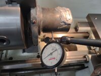
I double checked the runout, and it was within about .003" so good enough to begin machining the bore.
hub10.jpg

The first few passes were rough as it was an interrupted cut but after the initial bore began to take shape, it machined quite well. I snuck up on the bore and not knowing exactly how tight the bearing interference had to be and a phone call to the owner, I settled on shooting for a .001" interference fit. This was a captured bearing as it had the spindle going through with a nut to hold both bearings in as well as a center sleeve so I figured it didn't need to be as tight of an interference fit as some bearing fitments.
hub11.jpg

The ID was finished at .001" interference fit and I snuck up the outer flange of the hub's dimension.
hub12.jpg

Lastly, it was time to focus on the OD. The OD was less important and the owner even told me it could be left rough as it would clear the housing. However, I couldn't leave it rough so I wanted to finish it off so it looked as close to OEM as I could make it. After machining down I ran a file and some 180-grit emery paper over it and called it good. Lastly, added a chamfer to the ID of the bore and OD of the flange.
hub13.jpg

And it is complete ready for the owner to pick up.
hub14.jpg

The owner picked it up yesterday and was very pleased with the results. Especially since it saved his mower being a discontinued part.

Thanks for looking.
 
OP
Z

zmotorsports

ALLIANCE MEMBER
Joined
Oct 20, 2009
Messages
21,477
Location
Northern Utah
Well done, Mike. Always like to see your welding projects.
@Hakeem needs these for his van repair project.

Thanks Scott. These have been on my want list for quite some time now. A couple of weeks ago I needed one and so it was bumped up on my list.

Now that they are done and at the ready, it will probably be years before I need them again. :rolleyes:
 
OP
Z

zmotorsports

ALLIANCE MEMBER
Joined
Oct 20, 2009
Messages
21,477
Location
Northern Utah
Bravo Mike! Saw the first pic without reading any of the commentary and thought…no way. Turned out great. Cool repair.

Thanks Matt. When he sent me the picture I waffled on whether or not I even wanted to look at it any further but I decided to have him bring it by the shop and let me take a closer look at it. At that point I had him leave it and I'd give it a try, but no guarantees. He was shocked Saturday afternoon when I text him a picture and told him it was finished and he could pick it up.


The addition to the vise grips is sweet!
Ive had the out of line issue you spoke of any number of times while using locking pliers with my slide hammer but never really looked for a solution.
Impressive execution.

Thank you. I wish I would have done this modification years ago because I have just dealt with the mis-alignment issue all these years knowing there had to be a better solution.


Really nice fix on the spindle Mike!

Thanks Keith.
 

SilverJimmy

Well-known member
Joined
Apr 14, 2012
Messages
1,688
Location
Prescott/Flagstaff, AZ
Modifying those Craftsman locking pliers is a good use for them. I don’t know if you’ve experienced this, but every time I use the pair I have, the release mechanism pinches the bejesus outta my fingers. They release exactly opposite how ViseGrip and the new Snap-On pliers do, and bite me every time. Now that you’ve made a special application tool out of them and use them for a specific job, I don’t think they’d get a chance to bite again.
 
OP
Z

zmotorsports

ALLIANCE MEMBER
Joined
Oct 20, 2009
Messages
21,477
Location
Northern Utah
Modifying those Craftsman locking pliers is a good use for them. I don’t know if you’ve experienced this, but every time I use the pair I have, the release mechanism pinches the bejesus outta my fingers. They release exactly opposite how ViseGrip and the new Snap-On pliers do, and bite me every time. Now that you’ve made a special application tool out of them and use them for a specific job, I don’t think they’d get a chance to bite again.

Sterling, that is exactly why these were chosen for the modification because I have never been happy with them as far as locking pliers go.
 

ntsqd

Well-known member
Joined
Jan 22, 2005
Messages
997
Location
Lower left coast
Milwaukee's locking pliers products all feature an adjustment 'knob' that appears to be designed with the idea that a slide hammer type thing can be attached to them. The one time that I tried it I encountered exactly what drove this modification. Maybe if Milwaukee sees this they'll make a version that has the adjuster inline with the jaws instead of being at that angle?
 
To avoid these ads, REGISTER NOW!
Top Bottom