To avoid these ads, REGISTER NOW!

CBacres ex horse barn shop

OP
C

cbacres

Well-known member
Joined
May 28, 2010
Messages
5,998
Location
SW Florida
A lot of behind the scenes going on!

Picked up permit.😁

I could finally schedule a few days off from work, scheduled my site guy to bring in a few loads of fill in the next day or so, we will grub and build the pad week after next. I’ll get it formed and inspected, get a few conduits in and aiming to pour the first part of June.

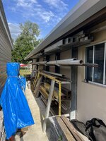
I moved most of my steel and aluminum stock yard onto the racks I built alongside the shop.
CE380993-7AEA-4638-9A1B-1574DC4ABD78.jpeg
Some of the sq tube will be used for a couple of stands. Yep, sits out back on blocks for years, put it on the rack, then take off a few months later to build something!
 
To avoid these ads, REGISTER NOW!
OP
C

cbacres

Well-known member
Joined
May 28, 2010
Messages
5,998
Location
SW Florida
Just about ready for site work guy to come in this Friday to scrape, fill and compact extension area.AF0D9A0D-6AC9-491D-9CF9-EE243719DFF3.jpeg

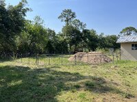
Moved the last of my steel boneyard. Took a fence down and temporarily put back up until building is done.
3B83E9F6-33A6-423C-8652-12B2D3D3A103.jpeg
Moved A piece of 1/4” plate on the plate mover.
08AAAF90-94A7-47FC-B547-DEA4BF3C240E.jpeg
I’ll get the large sections of steel pipe and the plate moved when machine is here.
85758674-B7F0-4E48-B81B-E3581F478724.jpeg
I’ll lay out building lines and elevations tonight.

Finally continuous movement, I can take some days off work to keep moving.
 

Attachments

  • 8DEA128D-419D-41EF-9280-964A7480986E.jpeg
    8DEA128D-419D-41EF-9280-964A7480986E.jpeg
    1.6 MB · Views: 12
OP
C

cbacres

Well-known member
Joined
May 28, 2010
Messages
5,998
Location
SW Florida
Finally I get started on the slab sub grade.

Hired a local site guy to grub the addition area, fill and grade to raise elevation. I layer out where the footer starts and had him cut with bucket to rough out footer to minimize hand digging.

Tomorrow finish roughing out footer, start forming.5EEE92B1-DD87-4AE7-8336-D8FA65D01A43.jpeg
7B18DF11-908E-4E54-8AE5-650A396145D3.jpeg
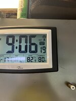
Nice humid morning.
8FF508E6-D33B-4450-8468-58741F9D5054.jpeg
I was aware of the larger piece of plate, the smaller thicker one was a surprise!
D41CDAA7-964C-4719-B34D-B88A242EE60C.jpeg
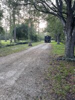
I‘m lucky they have great drivers. The way my property is situated, got to back down the driveway, drive through the pasture, back through a narrow gate to-get to shop area.
D4F6ED9C-10B1-4A8A-9060-019AB02053E4.jpeg
 

Attachments

  • 17DC36A1-CF0B-4CB6-A621-DC21E61F4F71.jpeg
    17DC36A1-CF0B-4CB6-A621-DC21E61F4F71.jpeg
    1.7 MB · Views: 21

Strouty

Well-known member
Joined
Mar 21, 2010
Messages
38,224
Location
Southern Maine
New outdoor table top?

At my shop when it rains there is almost always something new poking through the ground, I am not sure how this happens, but it does. Looking good on the progress, must be excited to see it really started!
 
OP
C

cbacres

Well-known member
Joined
May 28, 2010
Messages
5,998
Location
SW Florida
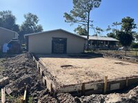
Poured the slab on Thursday, sent pictures to building manufacture to get building released. I’ll find out erection schedule date this coming week.

My last post was filling and grading the slab sub- base. I worked with the operator spot checking grade with the laser and we got it spot on. I had just a few high spots.

The engineering on this building called out a 12”x 15” deep monolithic footer, previous building just had a 12”x12” footer. That extra 3” of depth kicked my ***. There was a layer of hard pan like material, yep, at the bottom of the 12” mark.😳

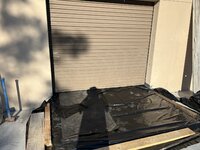
Anyway, got forming done, sprayed for termites, got plastic down, steel and passed footer inspection.
E24CC9B1-6C71-4CB0-BC03-C04000DC2873.jpeg
3353B0B3-2A1B-4672-A38A-207F192E8508.jpeg
6BC552A4-9F71-4F7E-8D75-D2925A567C7A.jpeg
680A89DC-0A25-4718-883B-9B9D5F5C330A.jpeg
 

Attachments

  • 7C6B1A92-65FE-44C6-8B88-6C472354D2E6.jpeg
    7C6B1A92-65FE-44C6-8B88-6C472354D2E6.jpeg
    1.2 MB · Views: 6
OP
C

cbacres

Well-known member
Joined
May 28, 2010
Messages
5,998
Location
SW Florida
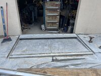
I have a platform lift that I’m going to install in the 4’x8’ pit I formed into the slab. The pit is 9” deep, allowing about 3/4” of adjustment when I install the lift.

I built a steel frame to form out the pit and to give me a steel edge in the concrete. I used 3”x3” x 3/8” angle for the top part of the frame, then added 6” of 3/16” plate for skirting to get down to bottom of the pit hole.

I got the 3” angle for free. Next time I’ll just spend the $400-500 on some 8” channel and be done a day and a half sooner and not have to lay on 150 degree plastic to weld the skirt to the angle frame. It’d been too heavy to handle if I welded all above ground on the stands.

Fab ing the angle frame.
9C673E8D-3A07-4330-BD7D-AE4498B99598.jpeg
I hammered in angle steel till it almost wouldn’t go anymore with a large sledge. I shot each with laser. 1DDB4298-8798-49AC-BAC7-5F25195348FB.jpeg

When I set the frame on angles, it was just about perfectly level, just had to shim one corner.
2B799298-EDE7-4E70-9F94-16F8C2418EF2.jpeg

Welding skirt up.
16A7DA29-BE96-4B5E-A572-353EBFCD38EF.jpeg
5D041730-091E-451C-ABB0-CA550E46ED6F.jpeg

Skirt welded n and steel rebar in place.
B924D6E5-7C61-44AB-85C8-00F1C91FBBF7.jpeg

This is a little out of sequence. I didn’t have time to install a conduit from the wall to the pit for the power and control wiring before the termite spray and did not want to disturb the soil. So, I just did my version of a jack and bore, using a piece of 2” galv pipe and a big sledge hammer!

70E7B357-3596-4434-BCDA-1183B7727CE9.jpeg
D77DFD6B-2042-4490-B3DA-94488AB84E91.jpeg
A249426F-6028-4174-9AA2-1058BEBC9FA5.jpeg
I drove the 2” in first, the used a piece of 1-1/2” steel pipe to remove the dirt from inside the 2” 4-6” at a time. When all was opened, pushed through a 1-1/2” pvc and turned 90s up at each end.
 

Attachments

  • CCB8D090-6B51-444C-9338-D2F9D4B76FEF.jpeg
    CCB8D090-6B51-444C-9338-D2F9D4B76FEF.jpeg
    1.2 MB · Views: 9
OP
C

cbacres

Well-known member
Joined
May 28, 2010
Messages
5,998
Location
SW Florida
On to the big day! Started with pump truck at 6:00 AM to get situated and lay out 220’ of 3” hose.
67EDF410-3DCA-4C49-A0D4-7AF4FAA1375D.jpeg
ACF1EE7C-DE81-4E10-8EDC-9B67B7165C3D.jpeg
39808A8E-927E-4D88-97E7-1731C4485319.jpeg
I painted the bottom of skirt with white paint, made it easy to see where top of concrete should be.
7DE033E6-2C5D-4026-8797-273073F1C13C.jpeg
I made a jig to slope a recess for the roll up door. Built a L shape form for each end, used a piece of aluminum channel for a guide and it worked great.

05B86B96-4130-40B8-84FE-F4AE93BF999B.jpeg
Rebar mats for overhead crane columns.

953F4CB1-71E5-42A2-9774-814F60CC8ECF.jpeg
936BB613-3146-4F00-8329-245B8A6FB0A1.jpeg3C55F530-E99C-4573-947A-0EB92C3F7B10.jpeg
The finishing crew was great, it was my intention to work the details on the roll up door slopes, the ramp and the pit floor. Once I showed them what wanted, it was get out of the way!.

81917F9F-BD58-4B33-8FAB-DA9D72B8161B.jpeg
I rented a street saw that night to cut control joints the next morning.
 

Attachments

  • 77F0D843-7833-49F1-88C7-FB7D88078655.jpeg
    77F0D843-7833-49F1-88C7-FB7D88078655.jpeg
    1.6 MB · Views: 11
OP
C

cbacres

Well-known member
Joined
May 28, 2010
Messages
5,998
Location
SW Florida
Been slacking on updates. Here’s a few pics to bring you all up to speed.
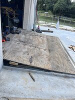
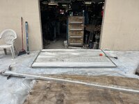
I built a temp cover over the ramp down to old shop floor to keep our Florida storms out of the shop until new building went up.

Anchored aluminum angle around the edge, sealed with a poly caulk.

I had aluminum planking to deck the opening, then used 3/4” plywood to create a slope away from the old shop.IMG_9254.jpegIMG_9251.jpegIMG_9316.jpegIMG_9310.jpeg

This did a great job keeping the rain out.
 
OP
C

cbacres

Well-known member
Joined
May 28, 2010
Messages
5,998
Location
SW Florida
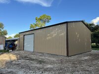
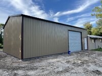
On to the building. Got a call from the building supplier, they could make it out the following week, about a month earlier than expected. Hell yeah!

Took four guys a day and a half to put up, they kept at it the whole time.
IMG_9588.jpegIMG_9587.jpegIMG_9581.jpegIMG_9579.jpegIMG_9578.jpeg
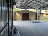
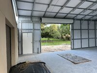
I basically ordered a three sided building. This company will not tie into any building that’s not theirs, so this is why the gable end is higher than old shop roof.
 
OP
C

cbacres

Well-known member
Joined
May 28, 2010
Messages
5,998
Location
SW Florida
Framing up the bottom of the gable end.
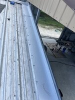
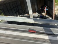
The old shop has PBR metal panels, I decided to have some galvalume flashing made up, basically L shape piece. I attached this to the square tube framing that I just framed in, the bottom of the flashing is 10” wide and it ends on top of a rib on the old roof.IMG_9967.jpegIMG_9968.jpegIMG_9995.jpeg
I finished putting the wall panels on the weekend there was a tropical storm passing by.
 

Attachments

  • IMG_9961.jpeg
    IMG_9961.jpeg
    698.7 KB · Views: 17
  • IMG_9963.jpeg
    IMG_9963.jpeg
    823.6 KB · Views: 15
OP
C

cbacres

Well-known member
Joined
May 28, 2010
Messages
5,998
Location
SW Florida
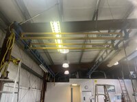
Next main project is to get this bridge crane set up. It’s a 500 lb capacity 12’x30’ Gorbel bridge crane. A friend told me about a shop closing up and this had to go. It’s ceiling mounted in these pictures, I’ll build the cross beams and columns to make it a floor mounted.

It has two bridges, each with a 500 lb capacity hoist. The hoists are three phase, but a converter will take care of that.

I ordered 4” steel channel to fab the cross beams, hopefully that material will be in next week.
IMG_2307.jpegIMG_2306.jpeg
 
OP
C

cbacres

Well-known member
Joined
May 28, 2010
Messages
5,998
Location
SW Florida
What’s talking so long?
Good to see things are moving forward. Crane will be super handy.
Just go on to your shop that’s stopped in time🤣
IMG_0130.jpeg
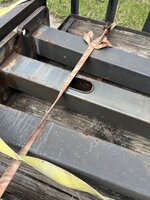
Picked up the columns and set up a work stand to prep for the crane support beams. These already have base plates, probably will add gussets to them.


IMG_0142.jpeg
Checking to see how close the bottom of each truss is off floor and then I’ll build in about an inch just to cover any possible adjustments. Shouldn’t need, everything is within a 1/4” now over a 14’x30’ area.


IMG_0148.jpeg
Thinking of fitting these openings for outlets. Can never have too many.
IMG_0132.jpeg
 
OP
C

cbacres

Well-known member
Joined
May 28, 2010
Messages
5,998
Location
SW Florida
Catching up with the bridge crane build. I cut and welded the top plates to the columns, built the main beam with two channels creating a I beam .
IMG_0243.jpeg
Cut the columns to length after measuring, marking out about three times. I was trying to get every last 1/2” of height for the crane without getting too tight to bottom of roof.IMG_0317.jpeg
Top plates welded on.
IMG_0242.jpeg
Channels laid out to create main beam that will sit on top of columns, the 30’ crane frame runner will hang from these.
IMG_0244.jpeg
The 4” channels were bowed and I used the column as a straight edge to clamp them back straight and weld together. Pieces of 1/4” flat bar was welded top and bottom to channels for spacing.
IMG_0413.jpeg
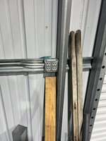
I added electrical boxes to each for access to inside of column in the future. There’s openings near the base on each, plan on install outlets in future.

Every thing was primed and top coated.
 
OP
C

cbacres

Well-known member
Joined
May 28, 2010
Messages
5,998
Location
SW Florida
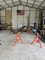
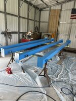
The main runners and the bridge trolleys of the crane was stored at my sons, he brought them down so I could paint and get ready to erect.
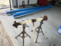
The main frame is 30’ long and about 350 lbs., not something we’re going to carry around much. I’ve had this old axle off a mixer for about 20 years and have used to move 56’ I beams when barn was built.
So I dug it out to use for these beams, but one tire finally gave up. My son will be here the next morning and had to figure something out quick. Buying new tires didn’t make sense as this wouldn’t be used much after.

IMG_0463.jpeg
IMG_0465.jpeg

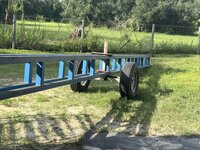
So, I had some trailer hubs with cut off axle pieces sticking out and some heavy angle iron.

IMG_0466.jpeg
IMG_0470.jpeg
And here is the 2024 custom beam mover.
IMG_0495.jpeg
I had to use the spare off my utility trailer and a tire off my BBQ gril.

IMG_0504.jpegIMG_0612.jpeg
All painted up.
IMG_0610.jpeg
 
To avoid these ads, REGISTER NOW!
OP
C

cbacres

Well-known member
Joined
May 28, 2010
Messages
5,998
Location
SW Florida
OK enough painting for a while. Time for erections.
I hung a 1/4 ton electric hoist off the roof framing to stand up the columns. There just a little bit too much to stand up by hand alone. I winched it upright and walked column over to its place.
IMG_0488.jpeg
When my son arrived, we carried the channel beam to the columns and hoisted it up.
IMG_0499.jpeg
Then with both of us, stood up the second set of columns in about 5 minutes. Had him help get the the other beam in place ready to lift.
IMG_0501.jpeg
Bolted and all thread hanging ready for main beam.
IMG_0725.jpeg
Rigged up second beam to lift and the hoist must of bought the ghost, think a gear stripped in it. I’ll just lift it in place when I rent the large AC lift.

I have everything in place ready to lift it up and be done. The weekends fly by!
 
OP
C

cbacres

Well-known member
Joined
May 28, 2010
Messages
5,998
Location
SW Florida
Rented a 650 lb. Capacity equipment lift to get the iron up. It took some maneuvering to get the 30’ main beams in place as the shop is only 40’ long. I marked the beams where they would intersect the support channel to minimize measuring/ marking up in the air.
IMG_0808.jpeg
IMG_0785.jpeg
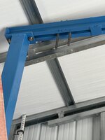
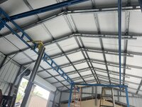
Used 3/4” grad 8 all thread and nuts to secure the main 30’ beams to the channels.
IMG_0801.jpeg
IMG_0756.jpeg
I set all the allthread and raised the mains up in between them and was pretty easy attaching the bottom plate, nuts and lock washers.
IMG_0815.jpegIMG_0816.jpegIMG_0817.jpegIMG_0837.jpeg
Now to work on running electric cable and setting up a 3 phase inverter.

Im glad to have this up, it’s been a haul.
 

Attachments

  • IMG_0785.jpeg
    IMG_0785.jpeg
    861.1 KB · Views: 17
OP
C

cbacres

Well-known member
Joined
May 28, 2010
Messages
5,998
Location
SW Florida
Having the two bridges is going to be very handy, do they need to be a certain distance apart to lift full capacity?
Strouty, I was just kidding around with friends about having 1,000 lb capacity by using both hoists at the same time!😜😜.

The design is just 500 lbs for whole crane. The two hoists is how I bought it, it was set up in a large specialty machine shop and there was multiple machines under this crane, a hoist at each end of the 30’.

Technically, you could do 500 lbs on each as long as each hoist was over a pair of columns at each end.

The two channel beams that hold up the works is made out of 4”, 7.2 lbs per ft channel. I couldn’t get Gorbel to tell me the exact spec of channel, so I went with the heavier.

The columns are 5” square tube, 3/16” wall with 1” thick base plates.

I may of overkilled it a little.

Thanks for stopping by.
 
OP
C

cbacres

Well-known member
Joined
May 28, 2010
Messages
5,998
Location
SW Florida
livin the dream!, looks awesome!, might be a double on the suckage :)
Thanks.

The availability of the crane came up right as I was planning this addition. Had it been a month or so earlier, it’d been “nice crane set up, been nice to have, but I don’t have anywhere to put it”.

The stars lined up on this one for sure.

The ironic part of fabrication and erecting this is it took a toll on my back. I partially sold it to my wife as it would help me save my back out in the shop!🤣🤣.
 
OP
C

cbacres

Well-known member
Joined
May 28, 2010
Messages
5,998
Location
SW Florida
Wow, very nice. You sure know how to get it done.

A plus on the two hoists. Let's say one guy takes a safety tumble and another guy drank too much, both can be escorted to the door together. :LOL:
Yep!
And the roll up door is close by so they can be loaded in the back!🤣

I like the way you think!
 

Strouty

Well-known member
Joined
Mar 21, 2010
Messages
38,224
Location
Southern Maine
Strouty, I was just kidding around with friends about having 1,000 lb capacity by using both hoists at the same time!😜😜.

The design is just 500 lbs for whole crane. The two hoists is how I bought it, it was set up in a large specialty machine shop and there was multiple machines under this crane, a hoist at each end of the 30’.

Technically, you could do 500 lbs on each as long as each hoist was over a pair of columns at each end.

The two channel beams that hold up the works is made out of 4”, 7.2 lbs per ft channel. I couldn’t get Gorbel to tell me the exact spec of channel, so I went with the heavier.

The columns are 5” square tube, 3/16” wall with 1” thick base plates.

I may of overkilled it a little.

Thanks for stopping by.
You might be surprised, usually when there are two bridges, they just add a spacer that keeps the bridges "X" distance away from the other one and then they are both able to pick full capacity.
 
OP
C

cbacres

Well-known member
Joined
May 28, 2010
Messages
5,998
Location
SW Florida
You might be surprised, usually when there are two bridges, they just add a spacer that keeps the bridges "X" distance away from the other one and then they are both able to pick full capacity.
That’s would probably be fine. Did t come across any data when researching and talking to the Gorbel engineers, just a common sense thing anyway.
 
OP
C

cbacres

Well-known member
Joined
May 28, 2010
Messages
5,998
Location
SW Florida
Been a bit since posting, we had a Hurricane swing by, nothing big, just sucked up time prepping for it.

Ive set the sub-panel and pulled feed wire, pulled the welder and outlet circuits for each side of the shop. Still have conduits and wiring for lights and other outlets, but what I’ve completed allows me to start moving equipment and cabs to new shop.

IMG_1243.jpeg
Sub-panel
IMG_1645.jpeg
I ran the conduits for welder and regular outlets under slab. Since I had this J-box, decided to use as a gutter and run all the wiring through a 2” conduit to the panel. This ended up cleaner than running separate 3/4” conduits from slab to panel.

IMG_1671.jpeg
Each side of the shop has outlets for the welders.

IMG_1900.jpeg
On the wall where welders will reside, I install an outlet for each. No more unplugging and lugging in.
IMG_1909.jpeg
All wired up!

IMG_1890.jpeg
Each outlet is two duplex 20 amps on separate circuits. Probably a little overkill for each wall, but there be plenty of plug in space. There’s three of these double outlets on each wall, with a dedicated circuit for the 2” belt grinder.
 
OP
C

cbacres

Well-known member
Joined
May 28, 2010
Messages
5,998
Location
SW Florida
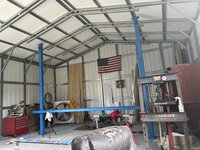
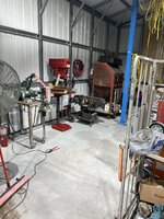
Started moving equipment over. Going slow as I decided to clean up each piece as it went in. If I don’t do it now, likely won’t get done for a while.

IMG_2142.jpeg
My most used is the DP and the bandsaw, these two may get swapped around. The cabinet sand blaster may end up elsewhere. Planning on steel storage on back wall, so flow of material to be cut will be close to saw.

IMG_2143.jpeg
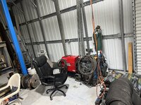
This will be the welder area. Still need to move the cabinet storing welding consumables.

I’ll get better pictures once most is in place.
 
To avoid these ads, REGISTER NOW!
Top Bottom