To avoid these ads, REGISTER NOW!

Show off your tubular projects here.

brianh

Well-known member
Joined
Apr 6, 2010
Messages
1,299
Location
grahamsville NY
The suspension sounds like the early TREK rear elastomer suspension. How long before the stress cracks showed up? Any lateral stiffness problems?

I put 1100 miles on it on and off road not really radical single track mostly carriage trails I am fortunate to be near Miniwaska state park a beautiful place to ride.

It did not start cracking until I started getting into more serious mountain biking the frame had some flex but not too much.

This is the bike I made to replace it instead of a pivot the rear suspension flexes on a carbon fiber plate, with a carbon fiber spring with an elastomer damper.

NASTYZEN very cool fabrication that is some serious skill.

Picture042.jpg
 
To avoid these ads, REGISTER NOW!

SWT Racing

Well-known member
Joined
Jun 13, 2009
Messages
137
Location
South Carolina
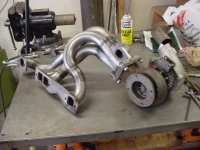
Nastyzen, could you explain the benefit of a 8 into 1 exhaust ? and what makes them so tricky to fabricate ? They sound absolutely bad a$$.

I would of thought that they would of gone 4 into 2 per side and so on because of the distance to go.
That collector is cool.:thumbup: The firing order goes in a circular motion and is the reason for that unique sound I would guess also.

To do true 180° headers (dual collector) in equal length is (or would be I should say. . .I've never done a set!) tricky. As Nasty stated, you would go in a circular (or maybe opposing on an 8-into-1?) pattern to maximize scavenging of the cylinder. This is why true merged collectors are used. Making 180° headers, is an to attempt to equalize scavenging on each cylinder. Because of the nature of most 90° crankshafts, you will have two cylinders fire sequentially at least once on each bank. By bringing tubes over from the opposing bank, you theoretically even out the exhaust pulses each bank.

Take a SBC firing pattern: 1-8-4-3-6-5-7-2. The 8-4 and 7-2 ignition events are right after one another. By merging into one collector, crossing over the #3 and #5 and the #4 and #6 bank-to-bank so that the exhaust pulses are spread apart evenly. This, in effect, maximizes cylinder scavenging because the low pressure area behind the prevous exhaust pulse helps scavenge the spent exhaust gasses from the cylinder, and in turn, helps pull a fresh intake charge in during cam overlap, especially on high RPM naturally aspirated engines.

There are some comments out there about never wanting to do a set of headers. Don't be intimidated by headers! Chances are that if you are a fabricator, someone will eventually ask for a set of headers. If you want to learn, and have some patience, they can be quite relaxing as Nasty pointed out. BUT. . .you need to take your time! Don't be afraid to scrap tubes if they are not to your liking or the fit up is poor. If you scrap some, use them as visual aids for another tube. Cut some 22.5°, 45° and 90° pieces as templates to lay out the tubes. Make sure your tube joint fit up is tight, as this will make them much easier to weld and less prone to distortion. Make sure to have the spark plugs in with a socket to check clearance.

Also, there are plenty of videos out there on the basic construction techniques. Many people are intimidated by the welding because of welds adjacent to other tubes. Just tack everything up, and pull each tube out individually to weld and put back in the header.

The headers on my twin turbo '72 Chevy Vega that I posed a pic of earlier are the first set I ever built. During a big car show/cruise, a local header builder I knew, Mark Weiss, and his buddy Reggie Jackson (the car collector, or "professional baseball player" as some would call him!) asked if I could build a set of headers for one of his cars, as Mark was too busy. I was floored!

You can do it. . .just take your time to do it right, just as it is with any fabrication project. Building your own set of headers is a very gratifying project, and will teach you a lot about tube fabrication. Just look at the pics in this thread for inspiration. There are some very, very, very impressive headers in this thread!

Are my headers perfect? No. Are they equal length? I tried! Did I have to cut on a bias to make some tubes fit? Absolutely!
 

Attachments

  • drivers_side_header_assy.jpg
    drivers_side_header_assy.jpg
    59.6 KB · Views: 182

neonnblack

Well-known member
Joined
Jun 7, 2010
Messages
4,913
Location
Reno, NV
Ok, question for you tubers and header builders. Well more of a request. What are the basics of building a header. I can weld, i could probably bend pipe, but never really put the two together before. I was interested in bending an exhaust and headers for my car (2005 stratus coupe 3.0 v6) Since headers are 500+ and exhausts are also outrageous. I want an idea of how to go about it. Is the way it bends for anything other than clearance and pressure? and also any decent ways to bend pipe without a mandrel? Thanks for the advice you guys in this thread seem to be amazing fabricators, and would love to learn some tricks. Thanks. feel free to pm me so it doesnt clog the thread.
 
Last edited:
OP
N

NASTYZEN

Well-known member
Joined
Jun 11, 2010
Messages
2,823
Location
St-Colomban,Que. Canada
Ok, question for you tubers and header builders. Well more of a request. What are the basics of building a header. I can weld, i could probably bend pipe, but never really put the two together before. I was interested in bending an exhaust and headers for my car (2005 stratus coupe 3.0 v6) Since headers are 500+ and exhausts are also outrageous. I want an idea of how to go about it. Is the way it bends for anything other than clearance and pressure? and also any decent ways to bend pipe without a mandrel? Thanks for the advice you guys in this thread seem to be amazing fabricators, and would love to learn some tricks. Thanks. feel free to pm me so it doesnt clog the thread.

There is no better way to make a wrinkle free,uniform diameter bend, than with a mandrel bender, that I know of. ( yet )
When I don't have the proper diameter tubing or the time to bend them myself. I buy '' U '' bends from Burns stainless or from Specialty products design in Cal.
Not only do you want a round cross section for proper flow, but also for fit when you have a rotation where you have cut the tubes. Imagine an egg shaped cross section. If you cut it in the bend and rotate it. The fit between the two will be awful.
The reason for headers to be '' curvy '' is because all the primaries should be equal lengths but all start from a different place or distance and have to end up at the collector.
I often use a similar dia. rubber hose at first, to determine and visualize the path that will be the easiest to the collector. To see if they can all be crammed in place and if the furthest tube will actually reach the place that you chose to put the collector.
Hope this helped a little.:)

First, you have to speak to an engine guy to determine the dia. as well as the length of tubing that you will need for your particular engine.
 

SWT Racing

Well-known member
Joined
Jun 13, 2009
Messages
137
Location
South Carolina
When I don't have the proper diameter tubing or the time to bend them myself. I buy '' U '' bends from Burns stainless or from Specialty products design in Cal.
You might try Woolf Aircraft in Michigan. Their prices are a bit better than Burns. I haven't bought from SPD in a while.

For mild steel, I found Stahl Headers to be a good source, and are great people to deal with.
 

neonnblack

Well-known member
Joined
Jun 7, 2010
Messages
4,913
Location
Reno, NV
There is no better way to make a wrinkle free,uniform diameter bend, than with a mandrel bender, that I know of. ( yet )
When I don't have the proper diameter tubing or the time to bend them myself. I buy '' U '' bends from Burns stainless or from Specialty products design in Cal.
Not only do you want a round cross section for proper flow, but also for fit when you have a rotation where you have cut the tubes. Imagine an egg shaped cross section. If you cut it in the bend and rotate it. The fit between the two will be awful.
The reason for headers to be '' curvy '' is because all the primaries should be equal lengths but all start from a different place or distance and have to end up at the collector.
I often use a similar dia. rubber hose at first, to determine and visualize the path that will be the easiest to the collector. To see if they can all be crammed in place and if the furthest tube will actually reach the place that you chose to put the collector.
Hope this helped a little.:)

First, you have to speak to an engine guy to determine the dia. as well as the length of tubing that you will need for your particular engine.

Thank you for the reply. I feel a need to bend my own. I dont want to buy a set of headers and exhaust for my car when i could probably do it on my own. Even if it costs more, i want the knowledge. Thanks again.
 

ZTFab

Well-known member
Joined
Jan 6, 2008
Messages
397
Location
Upland, CA
Thank you for the reply. I feel a need to bend my own. I dont want to buy a set of headers and exhaust for my car when i could probably do it on my own. Even if it costs more, i want the knowledge. Thanks again.

Just a heads up, with most rotary draw benders you wont be able to bend the tubing on a small enough radius for header work. A typical guideline for minimum Center Line radius for rotary draw bending is 3 times the diameter of the tube...and, as NastyZen already stated, the bend won't be uniform through the cross section.

Without a mandrel bender the tube will stretch on the outside of the bend as it compresses on the inside. For optimal performance the tubes need to be a uniform diameter all the way through the bend as can only be done with an internal mandrel.

There are some Rotary draw benders from companies like Ercolina, and the like, that will allow non-mandrel bending down to 1.5x the diameter of the tube but they are almost as much to buy as a mandrel bender and still won't make as uniform of a bend as the mandrel bender would.
 

neonnblack

Well-known member
Joined
Jun 7, 2010
Messages
4,913
Location
Reno, NV
Yeah, i looked into the pre bent pieces for the tighter radii i would need. And since this is a relatively low power motor, and will stay that way for a while would the .0X stretch really even bother performance is the rest of the header is prepped and measured and bent and collected correctly? And i have crazy ways of thinking(not like that sicko's) of a custom mandrel, What are typical mandrel materials anyways?
 

blue dog

Banned
Joined
Jul 4, 2010
Messages
4,051
Location
Culver City Ca.
Question for ztfab, Your skills as a welder are insane, i am in no way saying anything negative regarding your welds, so here it goes, The guy who did a bunch of work for me has mig welds that resemble yours, lets just say they are mig welds manipulated to look like tig welds or the stack of dimes. He knows what he is doing and is a fabricator at jimco in Santee. Recently an other friend of mine who is a welder in the aerospace world was over and commented that he was taught never to weld in this way and in no way would welds like that fly in his industry. I asked him if he thought they were inferior to a standard mig weld, He just said it goes against what he was taught, he as well told me that who ever did the welding has a high level of skill and control, just that he felt they were unorthodox welds and it made no since to him why one would try to make mig welds look like tig welds. So , my question is this, why does it seem like common practice in the off road fabrication world ?
 

Dirk Hollis

Member
Joined
Sep 1, 2009
Messages
13
Location
West Virginia
Lathe Electrical Cabinet Relocation.

Here are a few photos of the tubular support structure to hold up the electrical cabinet on my lathe. It needed to be relocated to the top of the lathe to fit the lathe against the wall. As with most projects it is a functional improvement that will get finished as time allows.
 

Attachments

  • Electrical Box Support.jpg
    Electrical Box Support.jpg
    87.3 KB · Views: 85
  • Electrical Box Support Bottom.jpg
    Electrical Box Support Bottom.jpg
    63 KB · Views: 77
  • Electrical Box Support Top.jpg
    Electrical Box Support Top.jpg
    59.6 KB · Views: 67
OP
N

NASTYZEN

Well-known member
Joined
Jun 11, 2010
Messages
2,823
Location
St-Colomban,Que. Canada
Wow! Been so busy last couple of weeks I was only able to lurk.....

SWT Racing; Are my headers perfect? No. Are they equal length? I tried! Did I have to cut on a bias to make some tubes fit? Absolutely![/QUOTE said:
I d'ont think that having equall lengths is quite as critical when you have a turbo setup. Nice work btw. Specially with them being your first set.:thumbup:

Nonhog, here's something better as promised.........:3gears: Click on images.


Nice project. Thanks for posting.

Lathe Electrical Cabinet Relocation.

Here are a few photos of the tubular support structure to hold up the electrical cabinet on my lathe. It needed to be relocated to the top of the lathe to fit the lathe against the wall. As with most projects it is a functional improvement that will get finished as time allows.

Nice.:thumbup:
 
OP
N

NASTYZEN

Well-known member
Joined
Jun 11, 2010
Messages
2,823
Location
St-Colomban,Que. Canada
Question for ztfab, Your skills as a welder are insane, i am in no way saying anything negative regarding your welds, so here it goes, The guy who did a bunch of work for me has mig welds that resemble yours, lets just say they are mig welds manipulated to look like tig welds or the stack of dimes. He knows what he is doing and is a fabricator at jimco in Santee. Recently an other friend of mine who is a welder in the aerospace world was over and commented that he was taught never to weld in this way and in no way would welds like that fly in his industry. I asked him if he thought they were inferior to a standard mig weld, He just said it goes against what he was taught, he as well told me that who ever did the welding has a high level of skill and control, just that he felt they were unorthodox welds and it made no since to him why one would try to make mig welds look like tig welds. So , my question is this, why does it seem like common practice in the off road fabrication world ?

ZT, Man I never saw someone get so much flak for his awesome welding skills......:wtf:
 

blue dog

Banned
Joined
Jul 4, 2010
Messages
4,051
Location
Culver City Ca.
ZT, Man I never saw someone get so much flak for his awesome welding skills......:wtf:

Come on now, not giving flack at all, just asking a question regarding zt's technique. His skill is outstanding, just that the stack of dimes look on mig welds is not common practice.
 

dragginbalz

Well-known member
Joined
Sep 19, 2005
Messages
197
Location
Illinois
Come on now, not giving flack at all, just asking a question regarding zt's technique. His skill is outstanding, just that the stack of dimes look on mig welds is not common practice.

I am just going to briefly explain my opinions on this subject.

I see it posted before as the "stack of dimes MIG weld, is not as strong as a smooth flat weld." Although I can agree with this since everywhere there is a ripple, there is a chance for a failure. BUT will his welds ever fail in that application? My thoughts are NO! The "strongest" weld is not warranted in that application.

You wouldn't use 5" x 3/4" lag bolts to anchor your 36" Ikea bookcase to the wall, right? That would be an extremely strong connection, but a single #8 screw in a strap into the stud is enough to keep it from tipping over. The "strongest" anchor would not be needed in this application.

That technique is done in short circuit MIG welding. You cannot do it with the voltage too high and you cannot do it in spray transfer. That is why you do not see it in bridge building, heavy machinery, construction, etc. The heat, thickness of material and voltage will not allow it.

Also, In those applications, strength is the ultimate goal. Those stress risers can cause a weld to fail, in that application. If you tried to short circuit on anything over 1/4" or so, your voltage would be too high, you would produce a lot of spatter (assuming you are not using over 80% argon where you can spray) and not get proper penetration.

So yes, trying to run a "TIG" type bead on an application that requires a spray transfer weld would not be correct. The voltage would be too low and it would fail. Not because of the bead and technique, but because it is not the correct weld or settings for the application. Running too hot of weld on the material is almost as bad as too cold.

Not saying you cannot run a smooth bead on short circuit at the correct voltage settings, but all settings the same, I would not say the smooth bead is any better than the stack of dimes bead.

ZT's welds are perfect for those applications. They are plenty strong enough and visually appealing.
 
To avoid these ads, REGISTER NOW!

welder4956

Well-known member
Joined
Apr 8, 2010
Messages
3,072
Location
Birmingham, AL USA
^^Very good assessment and I could not agree more. That technique would not be appropriate on welds for a bridge, building or heavy wall pipe welding, but is fine for fillet welds in thinner materials 1/4" or less.
 
OP
N

NASTYZEN

Well-known member
Joined
Jun 11, 2010
Messages
2,823
Location
St-Colomban,Que. Canada
THats dangerous, you might end up with too many broom pushers!

LOL! That's not happened yet....Spent most of Friday cleaning out the front shop.

Ok, how about some vintage Formula 5000 stuff?
This ones a Lola T-146.
First worked on it in the late 80's. Upgraded bits in the 90's

Fixed up the chassis,exhaust and suspension.

miscprojects228.jpg


miscprojects227.jpg


miscprojects226.jpg


miscprojects225.jpg


:beer::beer:
 
OP
N

NASTYZEN

Well-known member
Joined
Jun 11, 2010
Messages
2,823
Location
St-Colomban,Que. Canada
Very impressive work.

Mike.

Thanks Mike. If you think about it though,most of the stuff I do is copying or re manufacturing stuff that already existed.:bounce:

Aluminum railings
WorkStuff074.jpg

The saw, look a RIDGID shop vac
WorkStuff076.jpg

The coping machine
WorkStuff075.jpg

The first rail
WorkStuff073.jpg

Rails005.jpg

Rails004.jpg

Rails003.jpg

Rails001.jpg

Rails006.jpg

Nice work Tozi.:thumbup: I know how hard it could be to make railings fit properly. Specially when you have to fit it to something someone else has already built.
On a job with flowing water underneath, I guess you have to be careful not to drop anything. Ploop, there goes the hammer!:bounce:
Thanks for posting.
 
OP
N

NASTYZEN

Well-known member
Joined
Jun 11, 2010
Messages
2,823
Location
St-Colomban,Que. Canada
Well, racing being racing. **** happened at Daytona. The owner got er crossed up and rolled her in the infield,ripping of three corners and tearing up his ego......

miscprojects160.jpg


miscprojects161.jpg


miscprojects162.jpg


miscprojects163.jpg


Even in the day. This car was a flexy flyer and not a front runner.So we decided to stiffen up the chassis a little to help it out a bit.

miscprojects165.jpg


miscprojects164.jpg


Back to square one.

miscprojects159.jpg


Had to remake the front and rear wing mounts also.

miscprojects5060723.jpg


miscprojects5060724.jpg


miscprojects5060725.jpg


The rear wing is mounted so low I wonder if it actually does much?

miscprojects143.jpg


miscprojects142.jpg


Here it is at Watkins Glen, ready for some action.

miscprojects166.jpg


miscprojects167.jpg


miscprojects168.jpg


At speed.

miscprojects169.jpg


:beer::beer:
 

zmotorsports

ALLIANCE MEMBER
Joined
Oct 20, 2009
Messages
21,427
Location
Northern Utah
Thanks Mike. If you think about it though,most of the stuff I do is copying or re manufacturing stuff that already existed.


True, however, it still requires some amazing talents/abilities and puts you in a very small group of people with both.

I am envious of what you get to work on.

Mike.
 
OP
N

NASTYZEN

Well-known member
Joined
Jun 11, 2010
Messages
2,823
Location
St-Colomban,Que. Canada
Well, gee thank you Mike....I am privileged to have people entrust me with there beloved cars and various projects.
I'm an honest guy and I put my heart and soul into what I do. By the looks of your rail, so do you. I'm sure if the word gets around, people would flock to you with there various projects.
For what it's worth, if I were to be exclusive to racing, I would for sure go bankrupt quickly.:)
The real money, for me,is in production. Thru racing ,I came across some business people who need lots of things made for their businesses. That's why I got into CNC .
But the racing and technical stuff is what I enjoy most.:thumbup:

The way back files archives still have some neat things in them.......ahhh but those will only dribble out slowly.... I get a kick out of seeing other peoples stuff on here, so guys please keep posting your varied projects.
By all means,don't be intimidated by some of the higher end stuff on here. I like to see what and how YOU did things.
So look thru your old and new pictures and show it off here......I know your out there! Share!

:beer:
 

csp

Well-known member
Joined
Mar 23, 2010
Messages
5,719
Location
Franktown, CO
Well, gee thank you Mike....

You know that you can quote someone's post and delete part of it including the pictures, right? No need to make us scroll through the same photos everytime you're replying to someone in particular.....
 

gj67stang

Well-known member
Joined
Jan 9, 2010
Messages
897
Location
Sycamore, OH
2009 University of Dayton SAE Mini Baja racecar.

4130 1.125" Chrome-moly, 10hp restricted Briggs & Stratton, 14"+ of suspension travel:

DSC_3171.jpg


I was team captain/lead designer/lead fabricator.
 
OP
N

NASTYZEN

Well-known member
Joined
Jun 11, 2010
Messages
2,823
Location
St-Colomban,Que. Canada
You know that you can quote someone's post and delete part of it including the pictures, right? No need to make us scroll through the same photos everytime you're replying to someone in particular.....

Sorry dude! I didn't mean to upset people who have a beef with scrolling.....:bounce:

2009 University of Dayton SAE Mini Baja racecar.

4130 1.125" Chrome-moly, 10hp restricted Briggs & Stratton, 14"+ of suspension travel:
I was team captain/lead designer/lead fabricator.

That looks like fun to me.:thumbup:
 
OP
N

NASTYZEN

Well-known member
Joined
Jun 11, 2010
Messages
2,823
Location
St-Colomban,Que. Canada
nice work nasty .
Hope you and your family did not endure any damage in the microburst

Thank you for the concern. That was pretty wild!! For a minute there I considered crawling into my cnc lathe for fear of blowing away!:wtf:
Going to have to take care of a couple of leaning trees. I have very flexible trees so it seems.
Many of my neighbors weren't so lucky with trees on there homes and cars......
Power was back 10 PM last night.It rained so much my pond overflowed.....
All you hear are chainsaws and branch grinders today.
 

synik

Well-known member
Joined
Jan 5, 2010
Messages
192
K-swapped integra with turbo! Nice! How does it do at the track?

Haven't gone to the track yet. Though have some sweet runs against few 600whp Cobras. At 12psi boost, the integra gave it 5+ cars up to 120mph. :beer: Although will be pushing 25+psi soon with track.

But at low boost 12psi, I'm sure it will be in the low 11's. :beer:
 

Mario428

Well-known member
Joined
Dec 4, 2009
Messages
156
Location
PEI, Canada
miscprojects166.jpg


The radius rod (for lack of a better word) on the upper control arm is interesting the way it goes so far back.

You do some very nice work, enjoy your posts
 
To avoid these ads, REGISTER NOW!
Top Bottom