To avoid these ads, REGISTER NOW!

Electronic troubleshooting

OP
S

Snapped-off

Well-known member
Joined
Feb 22, 2012
Messages
4,810
Location
Indiana
I also think that some of the discussion has the collector and emittter reversed.
Some transistors in that package style have the C and E leads reversed, so you need to be careful when you're not sure of the part number.

I'm guessing that it's an NPN connected as a common emitter amplifier.

The emitter is connected to the common (negative) battery terminal.
You apply a small input voltage between the base and common and you get a larger output voltage between the collector and common.

The small input signal from the mysterious 'U1' is fed between the base and common (negative).
The larger output signal to the speaker is seen between the collector and common (negative).

So expect ...
Emitter connected to the common negative (with nothing in between).
Collector connected to speaker. Other side of speaker to common negative.
Often there's a cap between the collector and the speaker, but your circuit doesn't seem to have one there.
I was mixed up with the collector/emitter thinking input/output which Max corrected. Assuming the original transistor was a NPN, it was attached to the board with the collector going to the speaker, which is opposite of my initial misunderstanding.

So, I'm assuming the left yellow is the emitter going to the speaker, bottom yellow is the base going to the U1 brain, and the right is the collector which is going to the negative battery connection
This assumption was backwards.
 
To avoid these ads, REGISTER NOW!

RPH

Well-known member
Joined
Dec 17, 2006
Messages
4,190
Location
Michigan Thumb
Get a hundred of them. No doubt some purple smoke will be emitted once the repair commences. If your not used to working with them a couple will be sacrificed to the learning curve. Get the data sheet for the device. It will tell you what you need to know about it and how used.
 
OP
S

Snapped-off

Well-known member
Joined
Feb 22, 2012
Messages
4,810
Location
Indiana
Get a hundred of them. No doubt some purple smoke will be emitted once the repair commences. If your not used to working with them a couple will be sacrificed to the learning curve. Get the data sheet for the device. It will tell you what you need to know about it and how used.
I hope the only smoke will be from the solder. If I have to order more, I'll get extra. I should've bought extra just in case...

I'm not really worried about soldering it though.
 
OP
S

Snapped-off

Well-known member
Joined
Feb 22, 2012
Messages
4,810
Location
Indiana
Poor transistor. I've never seen one like that.
It might be a Bluetooth transistor since there's no pins..

I actually had trouble removing it. The solder sucker I have worked good for the middle hole, but I couldn't get it all sucked up from either outside hole. And I couldn't keep the solder flowing long enough to heat both sides to just pull the transistor out, so I ended up breaking the left pin. The right pin was broken out of spite.

I'll chalk it up to being a rookie.
 

RPH

Well-known member
Joined
Dec 17, 2006
Messages
4,190
Location
Michigan Thumb
Always kept a finger drill around when repairing through the hole board repairs. Surface mount brought a whole nether skill set for board repair.
 

dave*99

Well-known member
Joined
May 5, 2009
Messages
4,278
Location
Coastal NJ
The missing capacitor californiaHank mentioned also makes me think it is not an amplifier - but might be a switch. Essentially opening or grounding one side of the speaker. Maybe they are biasing part of the circuit through the speaker coil.

On another note regarding schematics of transistors - Easy to remember things this way.
Not Pointing iN or Points iN Please for NPN and PNP
 
OP
S

Snapped-off

Well-known member
Joined
Feb 22, 2012
Messages
4,810
Location
Indiana
The missing capacitor californiaHank mentioned also makes me think it is not an amplifier - but might be a switch
My initial thinking was it was acting as a switch for the speaker after reading a little about them, and just grounding the - side of the speaker.
On another note regarding schematics of transistors - Easy to remember things this way.
Not Pointing iN or Points iN Please for NPN and PNP
That's good to know, except I just don't know enough about transistors to understand the differences between the 2 types. :lol:
 

FordTruckWench

Well-known member
Joined
Jan 8, 2015
Messages
539
Location
California
That's good to know, except I just don't know enough about transistors to understand the differences between the 2 types. :lol:

A transistor is essentially two diodes pointing in opposite directions connected together. With NPN, they are back to back. With PNP, they are face to face. However, the diodes are not just connected - the silicon layers are so close together that strange physics affects happen in the junction.

In normal use, you cause a small current to flow between the base and emitter in whichever direction is forward for that "diode". This enables the physics affect to allow current to flow the "wrong" way to/from the collector.

Imagine that the collector and emitter are two points on a street. Connecting between them is a narrow alley - the base. Now imagine Sheriff Rosco Coltrane is parked at the collector. Daisy Duke pops out of the alley, calls to the Sheriff, and disappears back into the alley. The Sheriff starts driving down the street, is going too fast to turn into the alley, and ends up all the way to the emitter.

A good quality audio amplifier likely has both a PNP and NPN transistor in the output. One handles current from the positive voltage supply, the other current to the negative voltage supply. This way, the speaker coil gets energized in both directions. A cheap amplifier can get by with just one transistor, but the drive current won't be symmetric.
 
OP
S

Snapped-off

Well-known member
Joined
Feb 22, 2012
Messages
4,810
Location
Indiana
Switch soldered back up. No go.


Ok, the transistor came in. Probably should've ordered extra.

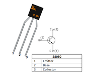
I have it set up according to the schematic for a S8050, with the collector going to the load (speaker -)
20211221_162756.jpg
Left - Collector
Middle - Base
Right - Emitter

We've got nothing. Not even a crackle if the collector is shorted. I don't think I did too bad a job soldering it. I could've used a smaller tip, but I used the smallest I had. None of the solder joints are shorted between each other.

Any further ideas?

Thanks all.
 
Last edited:
OP
S

Snapped-off

Well-known member
Joined
Feb 22, 2012
Messages
4,810
Location
Indiana
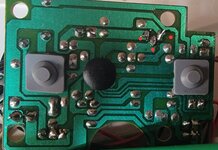
From solder blob to blob, I have continuity from these points. Should I have continuity from the emitter to the load? (Purple line) 20211221_162756.jpg
 

RPH

Well-known member
Joined
Dec 17, 2006
Messages
4,190
Location
Michigan Thumb
Look at the transistor body. You may have cooked it while soldering. Testing in circuit is tough if you don’t know what to expect. Try using the diode function on the meter to operate the transistor. Is it blocking when it should or shorted and dead? The terms more negative or more positive enters the discussion when working with transistors.
No smoke?
 
Last edited:
OP
S

Snapped-off

Well-known member
Joined
Feb 22, 2012
Messages
4,810
Location
Indiana
Look at the transistor body. You may have cooked it while soldering. Testing in circuit is tough if you don’t know what to expect. Try using the diode function on the meter to operate the transistor. Is it blocking when it should or shorted and dead? The terms more negative or more positive enters the discussion when working with transistors.
No smoke?
I will test it in a bit. Any idea how much heat would be too much? It only took a few seconds to solder each pin. That part actually went pretty smooth.
 

Max

ALLIANCE MEMBER
Joined
Jun 16, 2018
Messages
3,351
Location
Georgia
The solder joints look good and the pcb doesn’t look cooked. And a few seconds per lead is most likely ok.

What you are saying is the the red, blue, and yellow lines show a short along the lines? If so that is good. What is the resistance along the purple line? Is that also a short? If so that is a problem, as the collector and emitter should not be shorted.

If you are measuring continuity you must have a DVM or VOM? If so, I’d really like to know what the AC and DC voltages are at the base of the transistor referenced to the minus terminal of the battery.
 
OP
S

Snapped-off

Well-known member
Joined
Feb 22, 2012
Messages
4,810
Location
Indiana
The solder joints look good and the pcb doesn’t look cooked. And a few seconds per lead is most likely ok.

What you are saying is the the red, blue, and yellow lines show a short along the lines? If so that is good. What is the resistance along the purple line? Is that also a short? If so that is a problem, as the collector and emitter should not be shorted.

If you are measuring continuity you must have a DVM or VOM? If so, I’d really like to know what the AC and DC voltages are at the base of the transistor referenced to the minus terminal of the battery.
Yes, I checked continuity to the first connection in the path of each respective pin. So that's telling me it's soldered up OK. (I can assume)

I do have continuity on the purple line, the long one from the emitter to the speaker. That one has me puzzled because I didn't think I should have any there. Edit: I have continuity from the emitter to the collector.

I can check voltages. Why would I check AC on this?

If this were wires and relays I'd be fine. Drop down a scale to a pcb and transistor and I'm getting beat down by this thing. :lol:
 
Last edited:
OP
S

Snapped-off

Well-known member
Joined
Feb 22, 2012
Messages
4,810
Location
Indiana
Look at the transistor body. You may have cooked it while soldering. Testing in circuit is tough if you don’t know what to expect. Try using the diode function on the meter to operate the transistor. Is it blocking when it should or shorted and dead
Transistor itself looks good. Just as it was before I opened the package.

I need to read up on the diode test. Never had to do it, so I want to make sure I do it properly. Will the rest of the circuit cause any problem with this test? I won't be able to remove the transistor without breaking 1 or 2 of the pins, so it's gotta stay in unfortunately.
 
OP
S

Snapped-off

Well-known member
Joined
Feb 22, 2012
Messages
4,810
Location
Indiana
as the collector and emitter should not be shorted.
So what would cause this? Is this thing toast? These should only be connected when the base receives voltage, correct?

There's 38.75 ohms between the collector and emitter when the switch is off. When the switch is on its open (OL).
 
Last edited:
To avoid these ads, REGISTER NOW!

Max

ALLIANCE MEMBER
Joined
Jun 16, 2018
Messages
3,351
Location
Georgia
You can’t really rely on resistance checks when the power is on. The way your meter works is it puts a known voltage on its leads. It then measures the current at that voltage to figure out the resistance. So if the battery is in the circuit it will screw things up.

~40 ohms is more resistance than I’d expect to see if the transistor was shorted. It could still be shorted, or it could be other components on the circuit loading the meter. The best way to check would be to do a diode check with the transistor out of the circuit, but you already said you don‘t think you can do that safely.

I wanted the DC voltages so we can see how the transistor is biased. Right now it is not turned on - at least for the NPN we put in.

The reason to look for AC voltage is to see if the IC is driving pulses or AC into the base of the transistor. Kind of a cheap way to try to find out what we can without an oscilloscope…

I have to do a lot of errands this morning so it will be awhile before I can look at this. I need to draw out what I can of the circuit and try to figure out if we should have used a PNP, if the C/E should be swapped, or If whatever blew the original transistor blew the IC as wel
 
OP
S

Snapped-off

Well-known member
Joined
Feb 22, 2012
Messages
4,810
Location
Indiana
The reason to look for AC voltage is to see if the IC is driving pulses
Pulses as in PWM? I'll get the AC reading for you. Is it going from battery - to the base?
I have to do a lot of errands this morning so it will be awhile before I can look at this. I need to draw out what I can of the circuit and try to figure out if we should have used a PNP, if the C/E should be swapped, or If whatever blew the original transistor blew the IC as wel
I'm in no rush. I'm not sure the original transistor was blown. A slight wiggle got it working and I likely broke the pin that I found broken while desoldering.

I'll see if I can do a diode test on what's left of the original.
 

Max

ALLIANCE MEMBER
Joined
Jun 16, 2018
Messages
3,351
Location
Georgia
A diode test on the old transistor would be great as it can tell us if the original was NPN or PNP. Hopefully the base pin on the old one is still useable as otherwise the test won’t mean much.

Here is a link on how to do the test. It starts with diodes and scroll lower to transistors.
 
OP
S

Snapped-off

Well-known member
Joined
Feb 22, 2012
Messages
4,810
Location
Indiana
A diode test on the old transistor would be great as it can tell us if the original was NPN or PNP. Hopefully the base pin on the old one is still useable as otherwise the test won’t mean much.

Here is a link on how to do the test. It starts with diodes and scroll lower to transistors.
Will do. I'll try to get to it today. What about the AC readings? Where am I measuring?
 

Max

ALLIANCE MEMBER
Joined
Jun 16, 2018
Messages
3,351
Location
Georgia
AC measurement is between the base and emitter. We are trying to see if there are pulses or audio signals coming out from the IC.
 
OP
S

Snapped-off

Well-known member
Joined
Feb 22, 2012
Messages
4,810
Location
Indiana
AC measurement is between the base and emitter. We are trying to see if there are pulses or audio signals coming out from the IC.
I've got 0.000 VAC. Drop the meter down to mVAC and it hovers around 0.350 - 0.450 mVAC.

I can't do the diode test on the original transistor right now. I'm going to need some needles or pins to try and probe what's left of the leads.

Another thing now. Shorting the base and the collector gets static from the speaker. Could I just have a bad solder joint even if it's giving me continuity to the rest of the circuit?

I feel like I should order some more transistors and give it another go before I waste a bunch of your time. I'd hate it to be a weak solder job.
 

Max

ALLIANCE MEMBER
Joined
Jun 16, 2018
Messages
3,351
Location
Georgia
Shorting the base to the collector and getting static is expected as you are putting that .45V AC into the speaker. I would not do that again as it could overload or blow the IC.

If you can do the diode test on at least one junction of the transistor (BE or BC) then we can tell if it’s PNP or NPN. And that would help a lot as we don’t know for sure which pads got the emitter and collector.
 
OP
S

Snapped-off

Well-known member
Joined
Feb 22, 2012
Messages
4,810
Location
Indiana
Did they typo step 4?
3. Connect the terminal marked negative or common (usually coloured black) to the collector and measure the resistance. It should read open circuit (there should be a deflection for a PNP transistor).
4. With the terminal marked positive still connected to the base, repeat the measurement with the positive terminal connected to the emitter. The reading should again read open circuit (the multimeter should deflect for a PNP transistor).
Meter positive to base while connecting positive to emitter? That should be connecting negative to emitter right?

Editing:

BC - 0.569 mOHM
BE - 0.583 mOHM

This is with meter + to base and meter - to each. With meter - on base, they are both open. This is confirming NPN it looks like?
But I'm getting 25 mOHM across CE. This should be open? This is driving me wild because I'm getting a resistance reading, but it's not giving continuity on the meter.
 
Last edited:

FordTruckWench

Well-known member
Joined
Jan 8, 2015
Messages
539
Location
California
BC - 0.569 mOHM
BE - 0.583 mOHM

Looks like your meter doesn't have a proper diode test mode. In such a mode, the meter applies a limited current via the probes - and measures the voltage across the probes.

If you have a small battery (an AAA 1.5V battery will do) and a resistor (lets say 1K to 10K ohms), you can jerry rig a diode test mode: Join the battery and resistor in series (either order). The negative side of that assembly goes to your meter's negative probe. The positive to the positive probe. Set the meter to the 2 volt scale. Now test the transistor: If you've forward biased a diode junction, the meter will read about 0.7 volts. If reverse biased, the meter will show the battery voltage. If there's a dead short, you'll measure 0 volts.

If you have two meters with one of them being a cheapy that applies too high a voltage* in ohms mode, you can use them to do a diode test: Connect the probes in parallel. Set the cheapy to ohms - and ignore what it shows. Set the other to volts - probably the 2 volt range. Probe the device and observe the voltages as above.

* A good meter applies less than 0.3 volts in ohms mode so as to not forward bias diode junctions. This helps to measure resistors in circuit.

PS It may help if you trace out a portion of the circuit. You don't have to understand it - just show what components connect close to the transistor. In particular, there are several resistors, a capacitor, and a diode that are closely connected to the transistor, the speaker, and the COB (chip on board). Staring at the pictures I come up with a nonsense configuration.
 
OP
S

Snapped-off

Well-known member
Joined
Feb 22, 2012
Messages
4,810
Location
Indiana
Looks like your meter doesn't have a proper diode test mode. In such a mode, the meter applies a limited current via the probes - and measures the voltage across the probes.

If you have a small battery (an AAA 1.5V battery will do) and a resistor (lets say 1K to 10K ohms), you can jerry rig a diode test mode: Join the battery and resistor in series (either order). The negative side of that assembly goes to your meter's negative probe. The positive to the positive probe. Set the meter to the 2 volt scale. Now test the transistor: If you've forward biased a diode junction, the meter will read about 0.7 volts. If reverse biased, the meter will show the battery voltage. If there's a dead short, you'll measure 0 volts.

If you have two meters with one of them being a cheapy that applies too high a voltage* in ohms mode, you can use them to do a diode test: Connect the probes in parallel. Set the cheapy to ohms - and ignore what it shows. Set the other to volts - probably the 2 volt range. Probe the device and observe the voltages as above.

* A good meter applies less than 0.3 volts in ohms mode so as to not forward bias diode junctions. This helps to measure resistors in circuit.

PS It may help if you trace out a portion of the circuit. You don't have to understand it - just show what components connect close to the transistor. In particular, there are several resistors, a capacitor, and a diode that are closely connected to the transistor, the speaker, and the COB (chip on board). Staring at the pictures I come up with a nonsense configuration.
I do have a diode test mode, the meter is a Fluke 289. Auto ranging so I can only select Volts or mVolts

Those measurements were using just the resistance setting, as that's what the test called for. However looking at it I think those instructions are for an analog meter. :dunno:

I'll sketch something out.
 

FordTruckWench

Well-known member
Joined
Jan 8, 2015
Messages
539
Location
California
Those measurements were using just the resistance setting, as that's what the test called for. However looking at it I think those instructions are for an analog meter. :dunno:

A resistance test of a silicon junction isn't all that useful because it has a non-linear voltage to current curve. A diode test reading out in volts tells us a lot more about the functioning of the device.
 

Max

ALLIANCE MEMBER
Joined
Jun 16, 2018
Messages
3,351
Location
Georgia
What are you using to measure resistance? Is it a DVM? And if you do are you using the diode test or regular ohmmeter test?

The BE and BC measurements would say NPN. But .6 milli-ohm seems awfully low. And if you mean .6 meg-ohm that is too high.

And yes, CE shorted is a bad transistor…
 
OP
S

Snapped-off

Well-known member
Joined
Feb 22, 2012
Messages
4,810
Location
Indiana
What are you using to measure resistance? Is it a DVM? And if you do are you using the diode test or regular ohmmeter test?

The BE and BC measurements would say NPN. But .6 milli-ohm seems awfully low. And if you mean .6 meg-ohm that is too high.

And yes, CE shorted is a bad transistor…
Fluke 289. The link you gave me for the test specified to set the meter to ohms. Auto ranging meter, it was reading mOhm (milli-ohm).

That's wild it was initially working for a bit the very first time i wiggled the transistor. So it blew and then the base lead broke.
 
OP
S

Snapped-off

Well-known member
Joined
Feb 22, 2012
Messages
4,810
Location
Indiana
PS It may help if you trace out a portion of the circuit. You don't have to understand it - just show what components connect close to the transistor. In particular, there are several resistors, a capacitor, and a diode that are closely connected to the transistor, the speaker, and the COB (chip on board). Staring at the pictures I come up with a nonsense configuration.
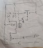
20211226_122023.jpg

Obviously I've left out half or more of the circuit. Mostly more resistors, caps, and switches. If more would be needed, it'd be easier for me to just label a picture of the backside solder joints on the board, so the whole circuit would be present.

I believe I tried to capture what's relevant. There's 5 or 6 switches to activate different songs on the track, and they all ultimately lead back to the chip.
 
Last edited:

Max

ALLIANCE MEMBER
Joined
Jun 16, 2018
Messages
3,351
Location
Georgia
The 289 is a very good meter so that is good. One thing to be aware of on a DVM is that the resistance range may use a relatively low applied voltage to measure resistance. This voltage can be too low to turn on transistor junctions so you don’t get valid readings. I pointed you at the transistor test article because I figured it would be better than something I wrote, but it seems that they forgot this little point. My apologies. Could you retest the BC and BE junctions using the diode test on your meter? I expect similar results but just to be sure…

On your drawing could you please describe what is what? ”T” must be the transistor, cob is the IC, and R and C make sense. But the rest are not clear. And how do the resistors have 3 terminals? Are they potentiometers or something else?
 
OP
S

Snapped-off

Well-known member
Joined
Feb 22, 2012
Messages
4,810
Location
Indiana
Ok I've done a proper diode test on the original.

With meter + on base
BC 0.7V
BE 0.7V

With meter - on base
BC Open
BE Open

CE is Open. (OL)
 
  • Like
Reactions: Max
OP
S

Snapped-off

Well-known member
Joined
Feb 22, 2012
Messages
4,810
Location
Indiana
The 289 is a very good meter so that is good. One thing to be aware of on a DVM is that the resistance range may use a relatively low applied voltage to measure resistance. This voltage can be too low to turn on transistor junctions so you don’t get valid readings. I pointed you at the transistor test article because I figured it would be better than something I wrote, but it seems that they forgot this little point. My apologies. Could you retest the BC and BE junctions using the diode test on your meter? I expect similar results but just to be sure…

On your drawing could you please describe what is what? ”T” must be the transistor, cob is the IC, and R and C make sense. But the rest are not clear. And how do the resistors have 3 terminals? Are they potentiometers or something else?
Not the best drawing. The 3rd branch isn't exactly off the resistor. The resistor is just inline on that part of the circuit and it branches off in different directions.

B+ B- are positive/negative battery
LD+ LD- are the load(speaker) connections
 
OP
S

Snapped-off

Well-known member
Joined
Feb 22, 2012
Messages
4,810
Location
Indiana
I can't edit posts anymore as I've hit a limit...

B+ B- are positive/negative battery

LD+ LD- are the load(speaker) connections

SW switches.

I'm not sure it was necessary to have the entire circuit and path out all the switches and the rest of the resistors and caps.

The diode ties into the B- leg and leads to a resistor that splits off into 3 different paths.
 
OP
S

Snapped-off

Well-known member
Joined
Feb 22, 2012
Messages
4,810
Location
Indiana
I know it's in the circuit, but trying the diode test on the installed transistor, I'm getting 0.7v regardless how the meter is biased, and it's reading across from CE as well.

Is this reliable at all being installed in the circuit? Wouldn't be surprised if I cooked it some how.
 

Max

ALLIANCE MEMBER
Joined
Jun 16, 2018
Messages
3,351
Location
Georgia
That was fast. :) Ok we made progress. The readings you gave for the transistor prove that it is a NPN and that it is ok. And we are sure about the base connection and just need to confirm the emitter and collector.
 
To avoid these ads, REGISTER NOW!
Top Bottom